Forum Replies Created
-
AuthorPosts
-
June 30, 2022 at 2:19 pm #39388
 wristpinParticipant
Very smart, but I have to ask, are the tyre treads supposed to be facing in different directions left and right?
June 29, 2022 at 12:44 pm #39379wristpinParticipantCan’t be taking off the flywheel every time I have to change or set the points. .
Going back to the days when “all” BS engines had points, ignition failure from component failure or maladjustment was comparatively rare – unless the points cover was not properly sealed and/or the machine was left outside during winter etc.
A Magnetron replacement is a nice neat solution using an original component but it shouldn’t be forgotten that as an alternative, an aftermarket transistorised points replacement unit used with the original coil is an equally reliable and maintenance free solution. I’ve got both a little used BS engined scarifier and a rotary cultivator, both fitted with Meco triggers some 30+ years ago. I regularly repair and restore Villiers F12 Sloper engines, mainly on Ransomes lawnmowers, and fit Meco units as a standard part of the rebuild: never had a failure yet.
The two trigger units that are readily available in the UK are Meco and Nova. I prefer the Meco as it’s a little more compact and may be fitted within many magnetos, whereas the Nova usually has to be fitted outside.June 29, 2022 at 8:54 am #39378wristpinParticipantThe transmission belt goes past a pulley that’s connected to the pedal. Is the belt the correct side of the pulley?
Quite possibly as simple as that !
June 28, 2022 at 8:49 pm #39374wristpinParticipantThe cover is 221046 and the screws 93014. All available , apparently.
The coil armature was 296834 and is shown as obsolete and no Briggs substitute offered.They don’t even suggest a Magnetron replacement, which is quite unusual, but
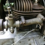
hopefully one of the current Magnetron coils will do the job. If so, it will replace the points and condenser, so you need not worry about the cover. However it is necessary to leave the points in place to keep the breaker plunger captive. Alternatively, shorten the plunger so that it does not contact the cam on the crank and glue it in place to keep the oil in. In the early days of Magnetron, Briggs sold conversion kits that included a small soft metal stud that was tapped into place instead of the plunger.June 28, 2022 at 6:58 am #39350wristpinParticipantIf it’s a Briggs engine of that vintage, the Model, Type, and Code Numbers are usually stamped into the engine cowling either adjacent to the spark plug or on the vertical surface on the carburettor side. Using those numbers will facilitate the correct information.
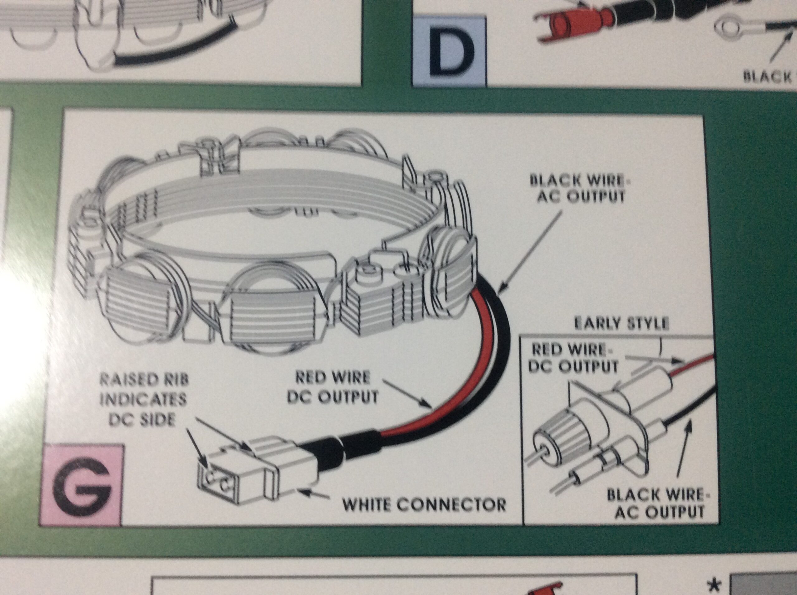
June 26, 2022 at 8:14 pm #39321wristpinParticipantThe engine has a sticker that states ‘Dual Circuit Alternator’. I’m unsure what the engine would be destined for but I’d guess a ride-on mower. The choke linkage is also independent of the throttle.
The Dual Circuit alternator has a two pin connector , one pin is rectified to DC for battery charging the other AC for lighting. If it follows the usual identification the connector is white and it’s cables are red for DC and black for AC. Early style have the same colour code for the wires but individual sockets mounted on a small bracket.
Attachments:
June 14, 2022 at 1:55 pm #39224wristpinParticipantNext on the agenda today will be to source a period-looking battery, then see if I can find someone who can sell me some wiring with the original trace colours to remake the wiring loom. I will also try to locate the original type of Lucas spade connectors with clear plastic insulators so that it doesn’t look out of place or too modern.
Just google vintage wiring and terminals – or similar. Here’s one to kick off with
https://www.autoelectricsupplies.co.uk/June 8, 2022 at 5:38 pm #39189wristpinParticipantAs I remember someone saying, every 5 minute job is only a sheared bolt away from been an all day job.
Never a truer word- or two!
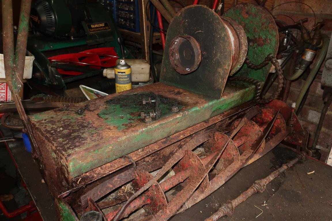
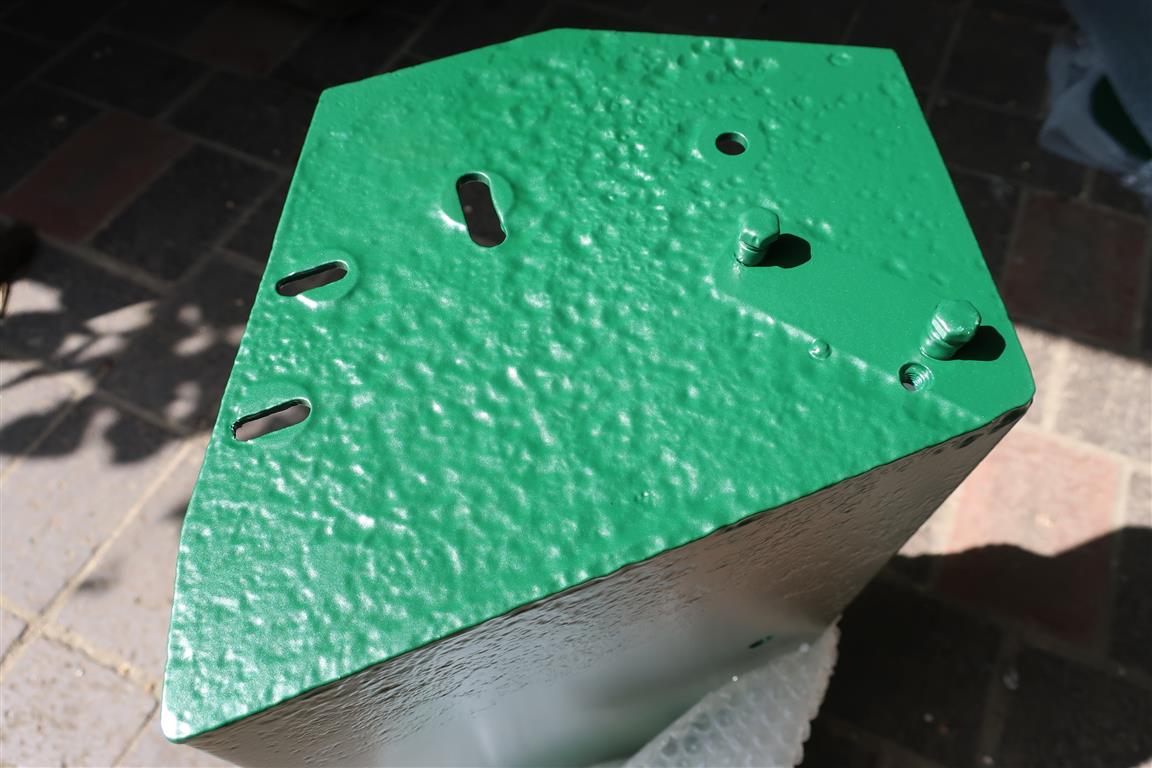
Back to the Anzani. Here’s an image to show the amount of metal wastage on the exposed to the weather side during its sojourn in the undergrowth, and another showing the complete absence of front rollers and the front roller shaft, with just the springs that separated them. The shaft, although corroded, could be persuaded into a piece of 15mm copper water pipe, and the homemade rollers were drilled to accommodate it.
The chassis is made of welded steel plate of generous thickness, so did not need structural reinforcement so rather than smother the wastage in filler, it’s been left as is.
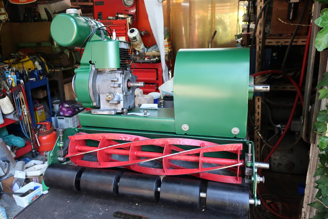
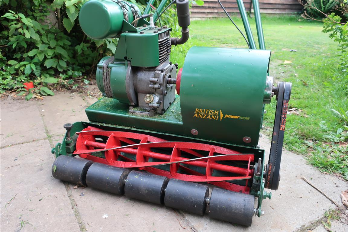
It has had a short run up the lawn and all is well mechanically, but at this stage in proceedings, other distractions have taken precedence. It could do with stronger springs in the centrifugal clutch, but the major job is to make a belt guard – unless anyone has one going spare. The shape of the guard is not immediately obvious, or how it is fitted. If anyone has a similar machine, an image or two of the guard will be greatly appreciated.Attachments:
June 8, 2022 at 5:06 pm #39188wristpinParticipantJust out of interest I wonder whether Mr Allett can supply an illustrated parts list that might show the original bearing set up.
June 6, 2022 at 8:16 pm #39185wristpinParticipantI may not have explained myself very well, Angus. The spherical part of the outer race is on the outside of the bearing, not the inside where the balls rotate, and it has been pressed into a parallel sided hole in
No, you were quite clear and that’s what I was referring to. The spherical outer allows the rigid bearing to self align in a female spherical housing, an arrangement that will be familiar to anyone who has worked on Atco Standards of the 1920s. It’s surprising that a machine designed and built in the 1970s uses that style of bearing as the self aligning bearings as we know them were, by then,in common use.
June 6, 2022 at 5:24 pm #39183wristpinParticipantwe all know that sealed bearings don’t come with much grease inside
There is a reason for that, and perhaps not the obvious! Same as for wheel bearings, if they are over packed with grease the balls skid round en masse rather than rolling round the track, and end up with flats on them.
Not sure that I quite follow what may have been done by a previous repair but bearings with a spherical outer race are readily available, from the likes of Simply Bearings.June 3, 2022 at 8:43 am #39158wristpinParticipantMy choice of extraction method for this job was made due to the probable fragile nature of the alloy sole plate; not to mention the comparative rarity of finding another.
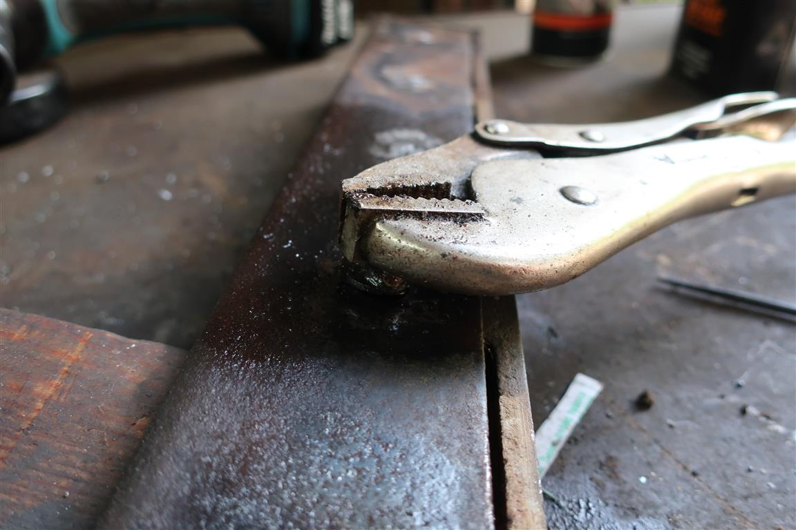
When it comes to frozen bolts and bottom blade screws etc, a couple of minutes spent thinking and forming a plan can avoid half an hour of aggro, or worse. Better to avoid creating the problem than spend time and resources on rectification.June 2, 2022 at 2:34 pm #39147wristpinParticipantAnzani part two – bottom blade and rear roller.
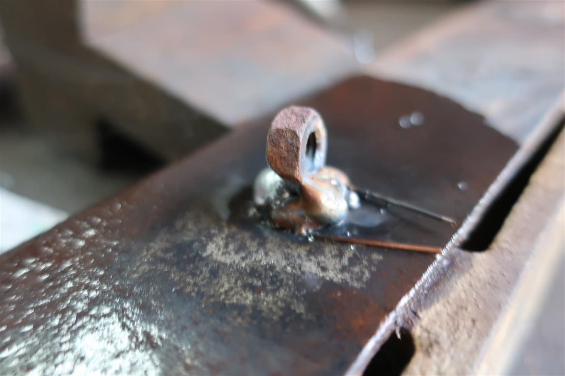
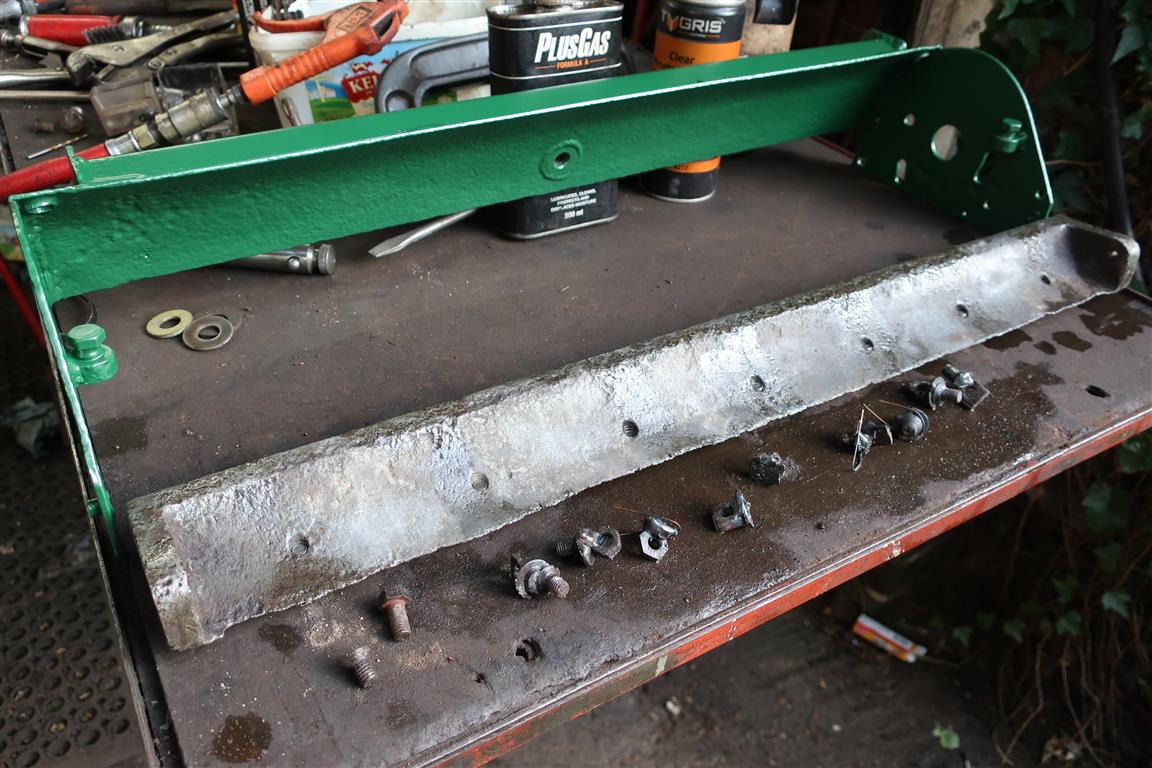
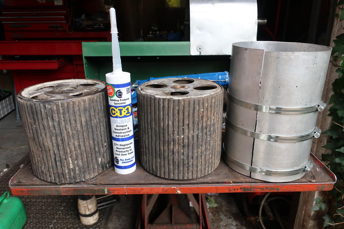
The bottom blade should be lipped, but the lip was nearly gone. That combined with a well-worn cutting cylinder meant that they barely touched. A fair amount of asking around including Garfitts failed to produce a blade, but a sort through the “might come in useful” bin produced one for a Greens Zephyr which lent itself to some modification. The next issue was that the sole plate as well as being an alloy casting was a bit corroded and wasted and not likely to put up with any welly from an impact driver, so each screw had to have the welding treatment. The screws were countersunk and flush with the blade, so a washer was welded to each with a loop of mig wire underneath to prevent the cooling shrinkage pulling the washer down onto the blade. A nut on edge was then welded to the washer – safer and more effective than welding straight to the screw. The heat from the weld plus penetrating fluid and a bit of gentle wiggling resulted in 100% success, with no sheared screws or damaged threads.
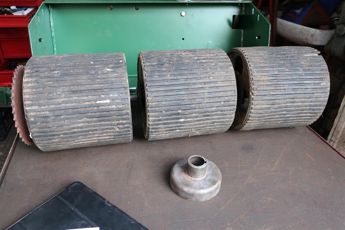
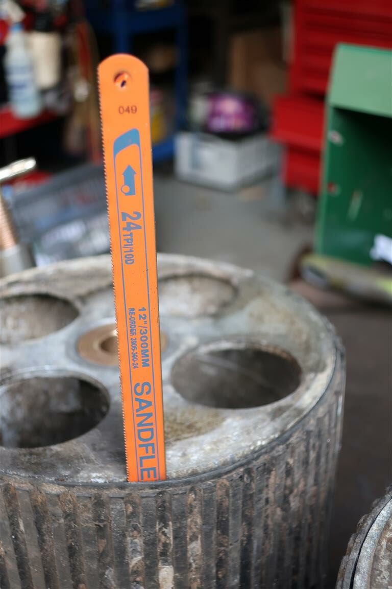
Using the Anzani blade as a template, the Zephyr blade was modified accordingly, some holes being redundant and others “just not right” being welded up and redrilled.The rear roller. This is a three section alloy rubber covered unit. The main issue there was that moisture had crept between the rubber and alloy, the consequent corrosion having blown the rubber away from the alloy. My concern was to preserve the rubber if at all possible. The extent of the separation was such that it was possible to insert a hacksaw blade between the rubber and alloy and gently remove the corrosion – blowing it out with the air line. It was then a matter of re-securing rubber to alloy. After considerable consultation, a suitable adhesive was chosen and squirted in from each end of each section one at a time, with each being left to cure clamped up with an alloy sleeve and large Jubilee clips. It seems to have worked and put up with some gentle experimental trips up the lawn!
Apologies, Had an issue with image posting and they are out of order.
Attachments:
May 23, 2022 at 9:55 pm #39087wristpinParticipantLooking good. They certainly had their money’s worth from the air filter element! We used to have an excellent auto electrical firm but such as is the way of things, the partners were getting on in years and the property developers could see space on their site for several substantial houses.
May 20, 2022 at 6:28 pm #39065wristpinParticipantI’m not familiar with the dimensions of the Kubota filter that you mention but Briggs use (used to use?) a very short one for certain applications of the Vanguard twin. Might not have the throughput capacity though.
-
AuthorPosts