Home › Forums › Groundcare Machinery › Grass Cutting Machinery › Allett Regal No.1
Tagged: Allett Regal Mk1
- This topic has 96 replies, 10 voices, and was last updated 3 years, 8 months ago by
 trusty220.
-
AuthorPosts
-
June 6, 2022 at 7:13 pm #39184
 trusty220Keymaster
I may not have explained myself very well, Angus. The spherical part of the outer race is on the outside of the bearing, not the inside where the balls rotate, and it has been pressed into a parallel sided hole in the end of the roller. A better solution will be to have a bearing with parallel outer sides so that it fits the hole better and stays put.
I’ll post some more photo’s once I’ve got the new bearings.
June 6, 2022 at 8:16 pm #39185 wristpinParticipant
I may not have explained myself very well, Angus. The spherical part of the outer race is on the outside of the bearing, not the inside where the balls rotate, and it has been pressed into a parallel sided hole in
No, you were quite clear and that’s what I was referring to. The spherical outer allows the rigid bearing to self align in a female spherical housing, an arrangement that will be familiar to anyone who has worked on Atco Standards of the 1920s. It’s surprising that a machine designed and built in the 1970s uses that style of bearing as the self aligning bearings as we know them were, by then,in common use.
June 8, 2022 at 8:07 am #39186trusty220KeymasterIn view of the length of service that this machine has given it is conceivable that somebody with experience of old machinery has modified it to suit what they had at the time. The circular cups that the bearings fit into have been welded to the ends of the roller but around them are the remains of the threaded sections of three bolts, so I guess that the original bearing had a cast flange that bolted to the end cap of the roller. The person who made the circular cups has used the remains of the threads to centre the cups, then welded them in place; not a bad solution to get the mower back working again without too much outlay.
How’s the Anzani coming along, Angus?
June 8, 2022 at 5:06 pm #39188wristpinParticipantJust out of interest I wonder whether Mr Allett can supply an illustrated parts list that might show the original bearing set up.
June 8, 2022 at 6:59 pm #39196trusty220KeymasterThe only listing that I have is of the combined Operator’s Manual and Spare Parts List. The pictures are very crude line drawings with no detail at all, just an arrow pointing roughly to the region and a part number.
It’s starting to come together bit by bit, more photo’s soon.
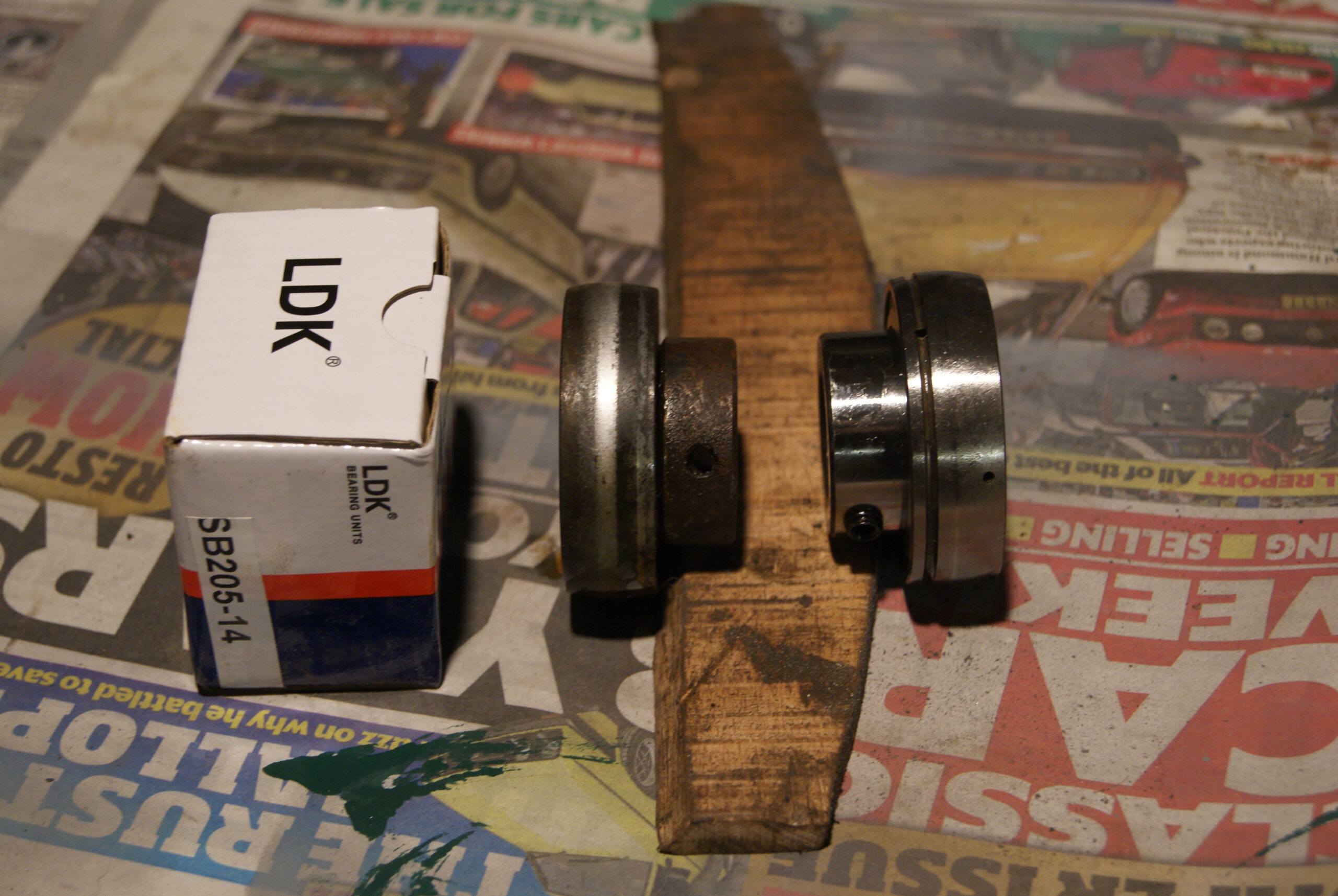
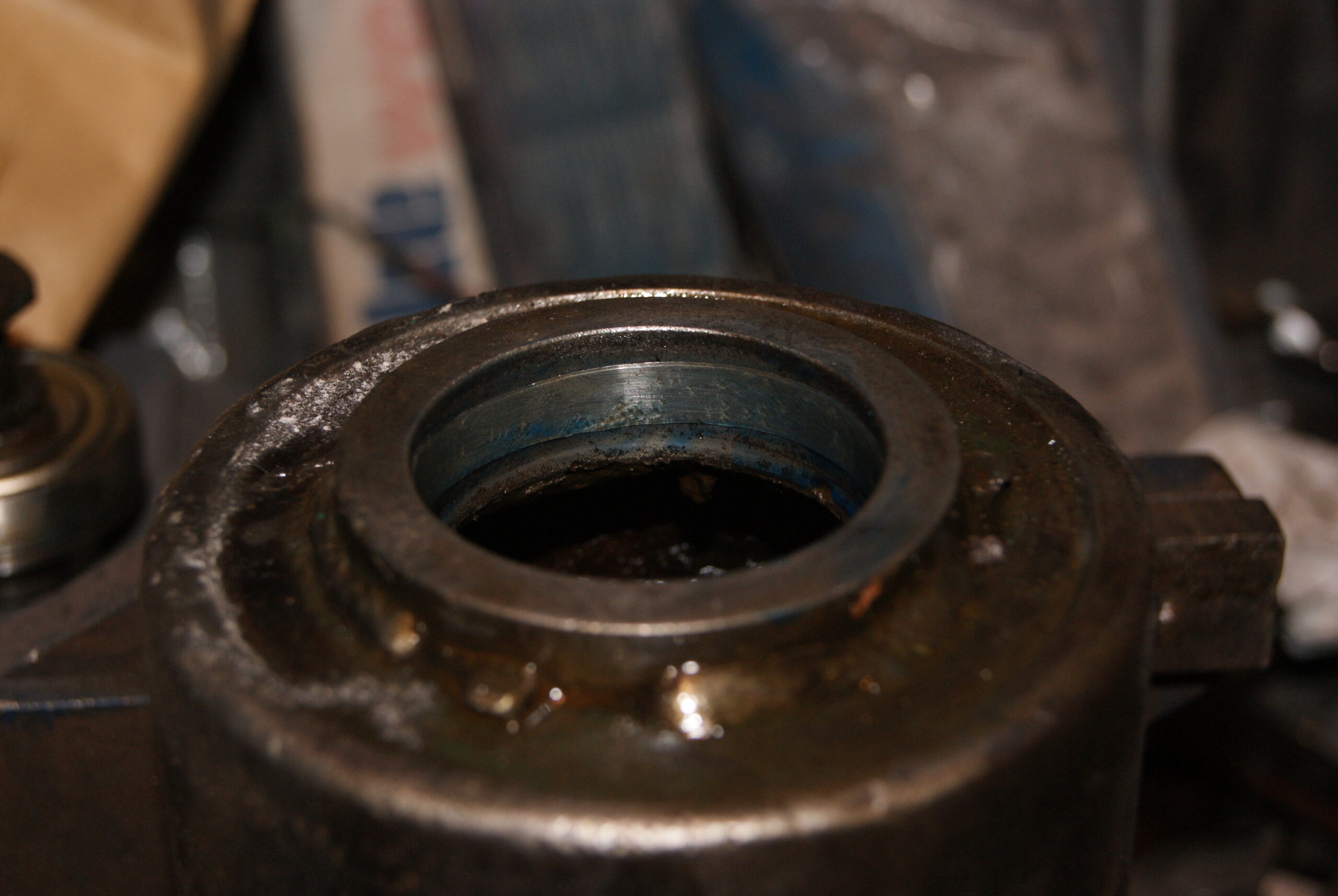
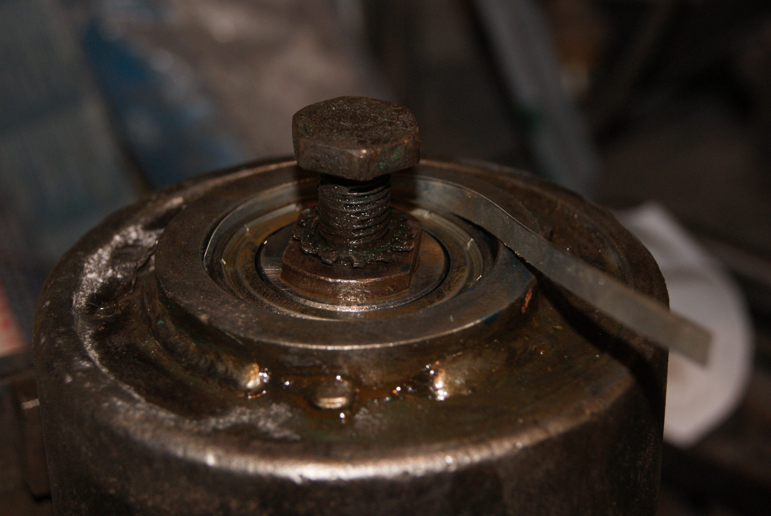
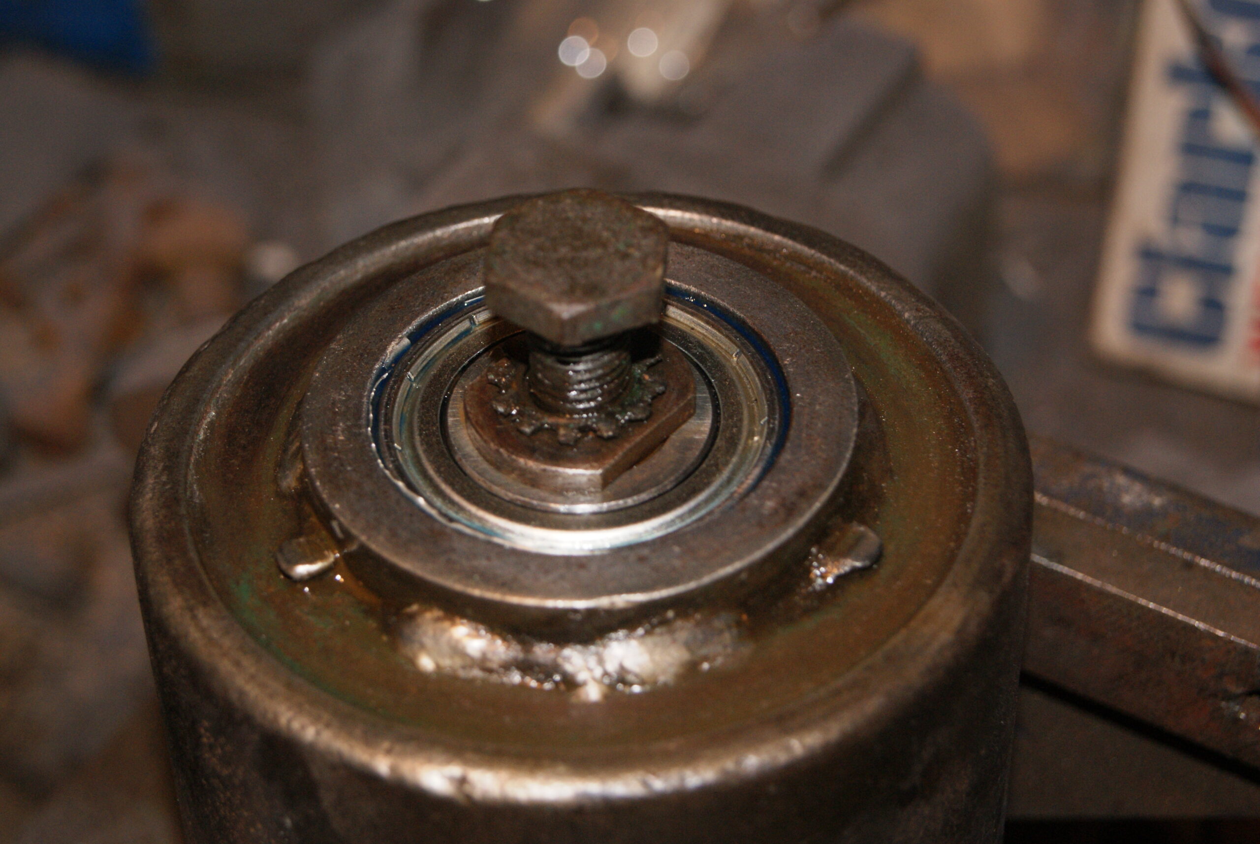
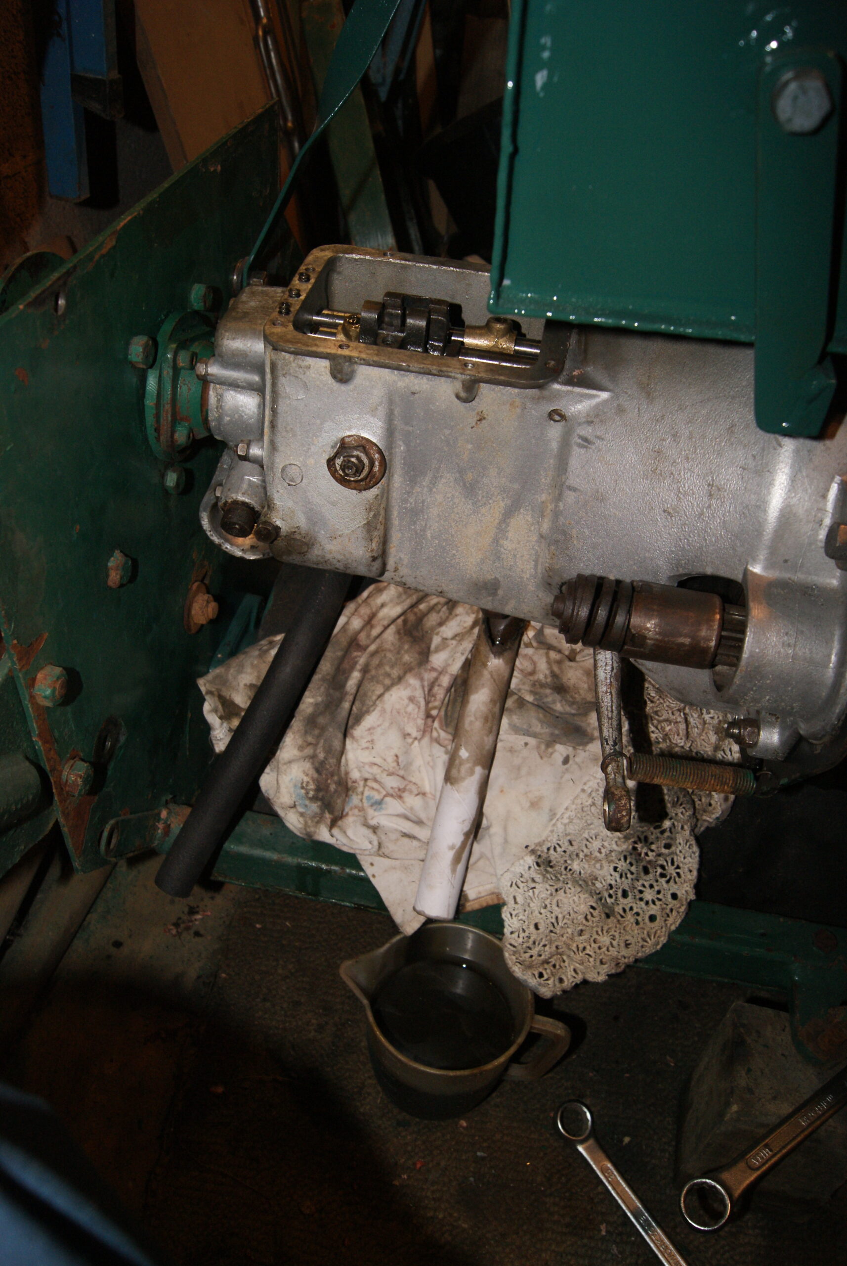
June 8, 2022 at 8:04 pm #39197trusty220KeymasterThe cunning plan for the bearings had to be modified slightly. The bearing supplier could only get bearings that were the direct equivalent to the old ones as you can see from the first photo. This meant that the outer profile was spherical and had to fit into a parallel sided hole; on the one side this wasn’t a problem as the cup was still unworn, but on the other side I dropped the bearing into the cup and, with a feeler gauge, measured the excess gap to 20 thou. I then cut two strips of 10 thou shim steel and “glued” one in the back of the cup using Wurth Thread Lock. Pushing the bearing in on top of it to spread it out so that the Wurth could get a good purchase, I then squeezed some more Thread Lock down the gap and worked the second strip of shim steel into the gap, then left it all overnight to set.
This morning I pushed and pulled both ends and could find no movement. I would stress that this mower is destined to be a display piece and so that quick fix on the roller should be OK, otherwise I may have been tempted to build up the wastage with weld and trimmed it back by hand with a die grinder and straight burr.
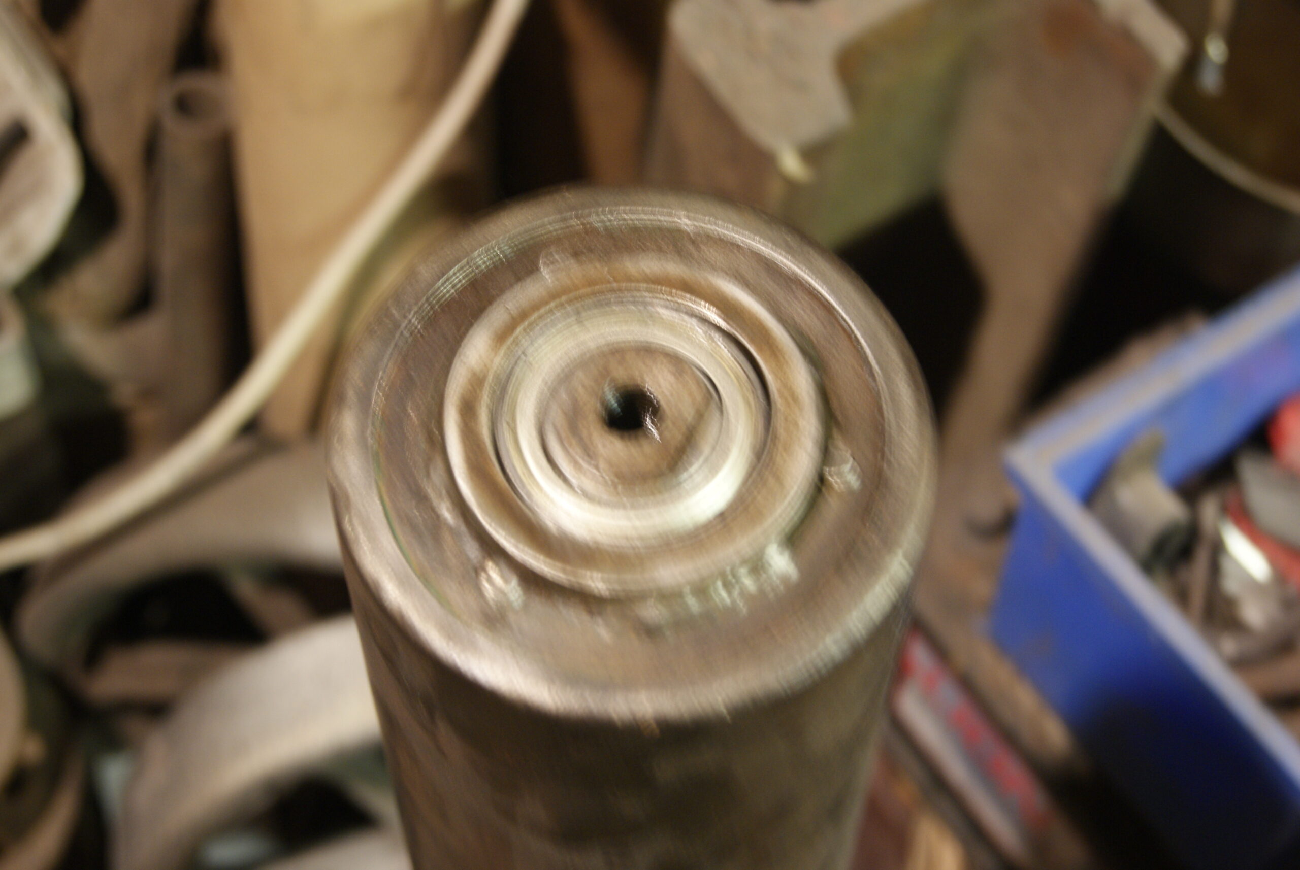
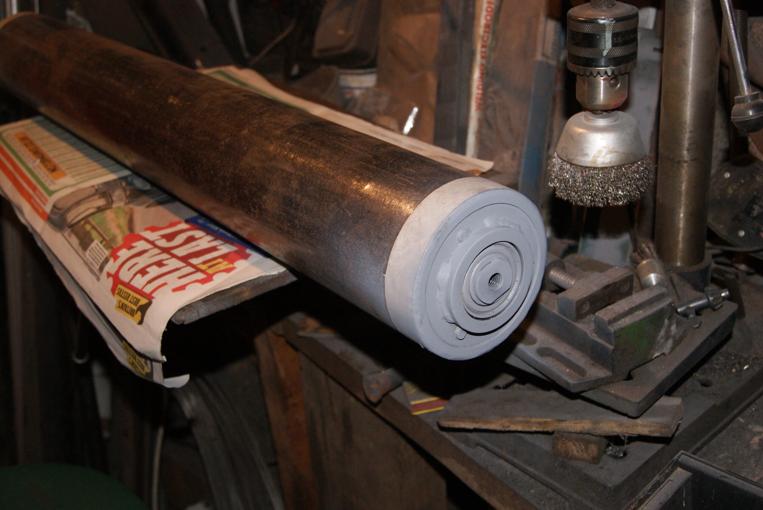
The roller tube was covered in a surface layer of rust and dirt, and so an hour outside with angle grinder and flap wheel saw a lovely shine return to the surface. I’m undecided how to finish the outer part of the tube as I prefer to see rollers in shiny, natural metal; I may experiment with Anchor Wax to see what it looks like and to see how hard wearing it is.
The ends of the roller were masked up and primed, then painted green and put to one side so I can get on with the rest.
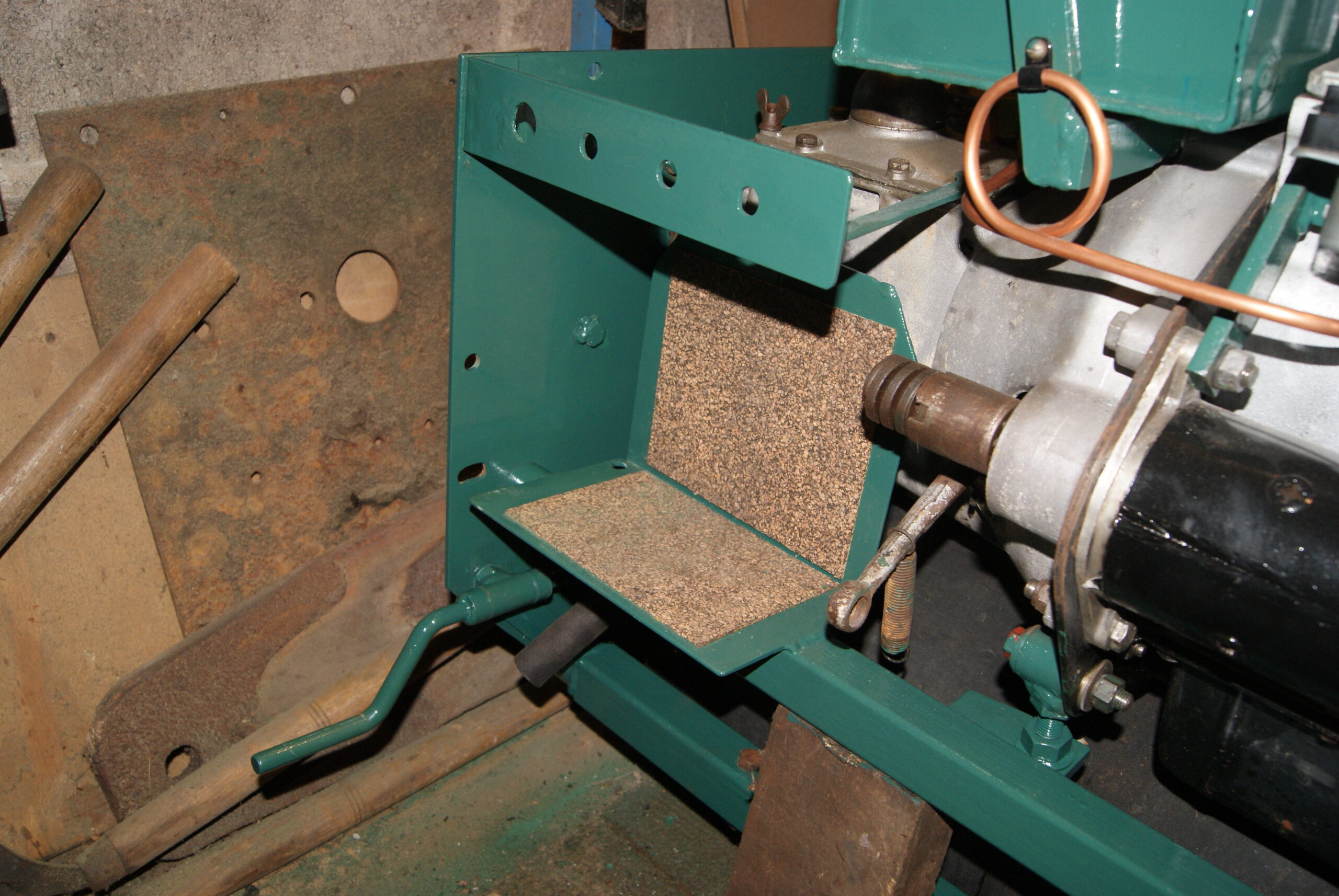
The gearbox deserved some attention next and so the top cover was removed to inspect the insides. At the same time the oil was dropped out and it definitely needed changing having the colour and consistency of molasses. I left it to drain whilst cleaning up the gasket faces, then thought I’d have a go at the fuel line from the tank to the pump. The one that came off was a piece of neoprene that had hardened and so I decided to replace it with a length of copper pipe in 1/4″. The only problem with this was that the pipe had to find it’s route around the ignition coil, so the improvised wooden jig was brought out again and dog-legs made to take the pipework around the back of the coil, then up to the tank supports where a complete circle was formed to absorb vibration, then up to the Ewarts tap on the bottom of the tank.
The rear crossmember was finally relocated with it’s fresh coat of paint and a couple of cork pads for the battery to sit on so that it doesn’t wear through the paintwork. A long day, but when it’s pouring with rain the garage is probably the best place.
Attachments:
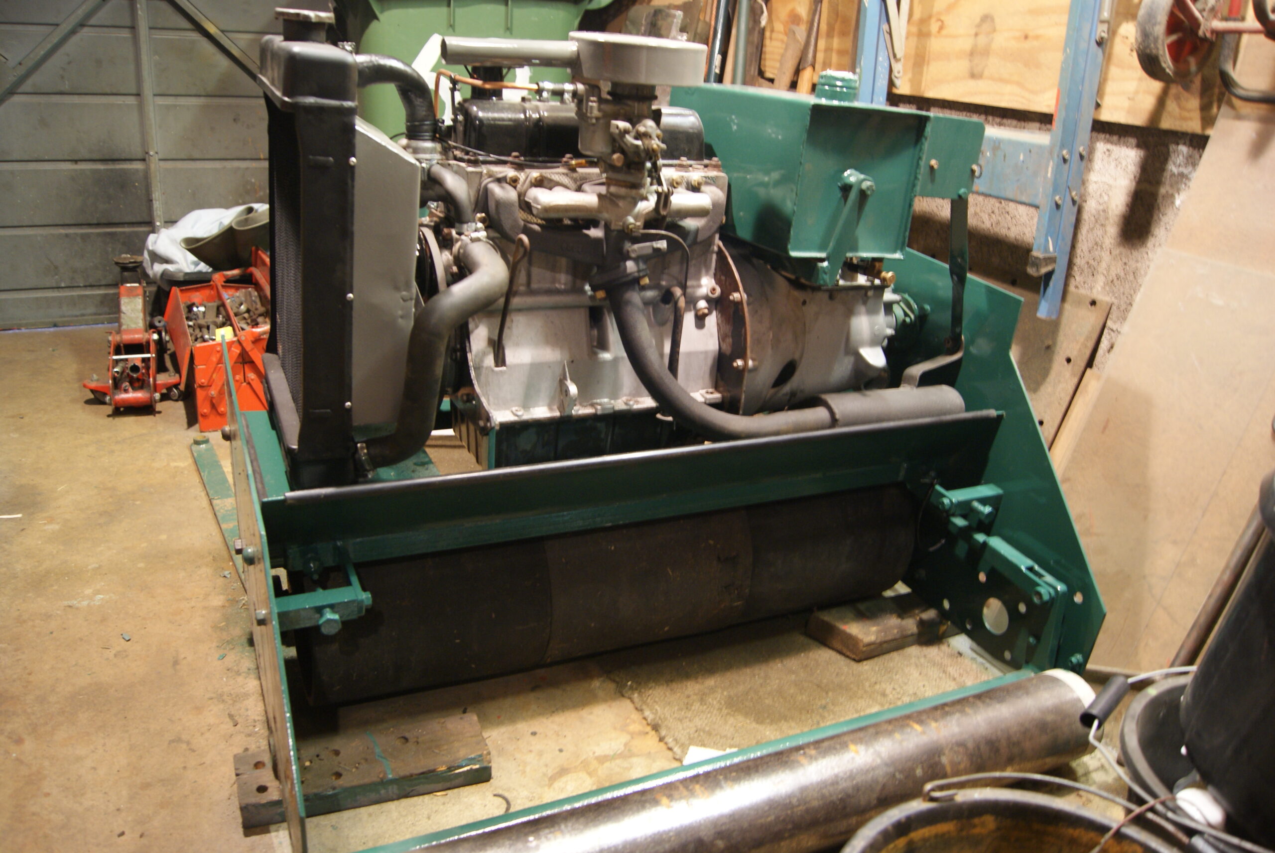
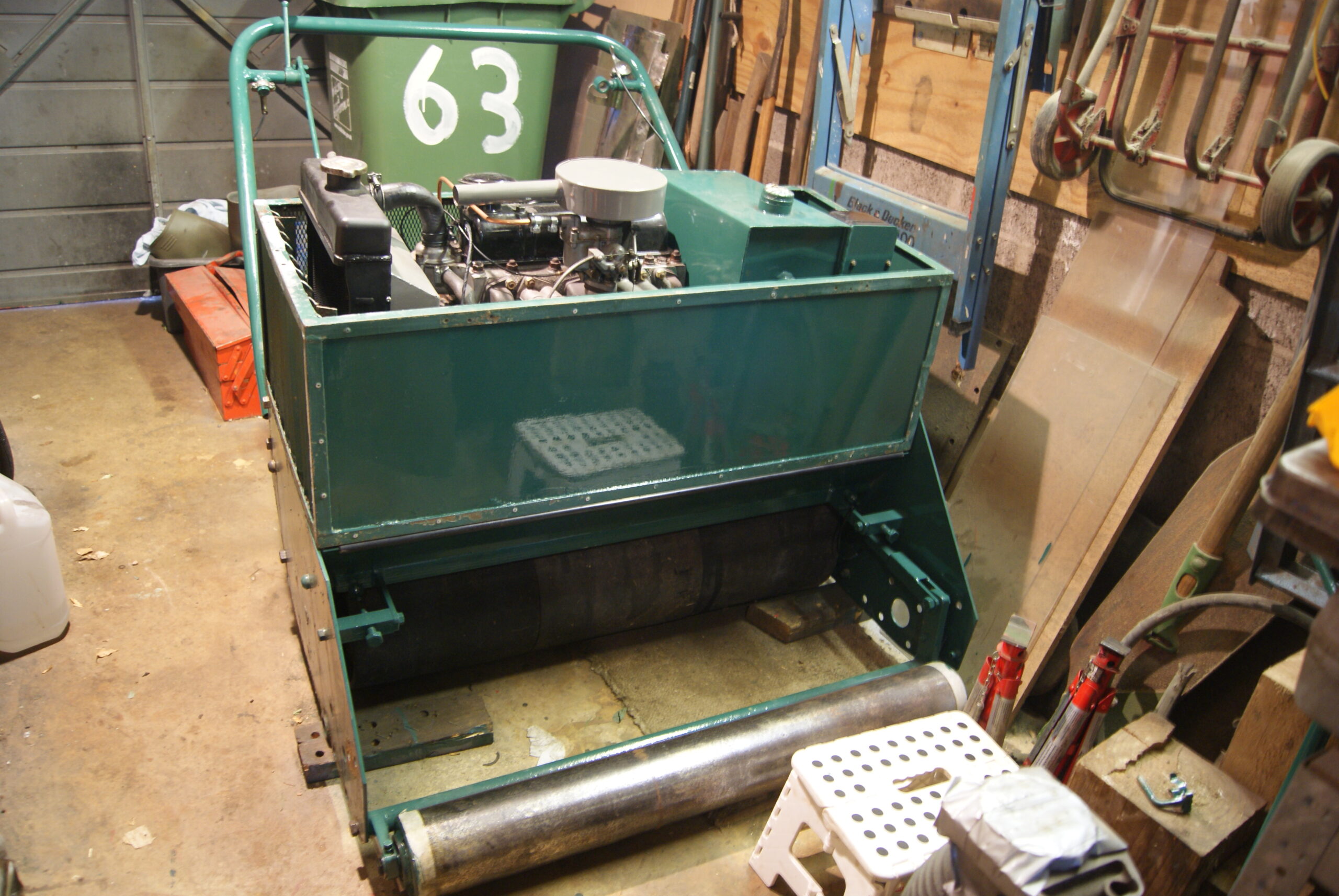
June 14, 2022 at 11:04 am #39214trusty220KeymasterI think I owe you quite a few pictures as progress has been rapid of late, mainly due to parts that I have already finished finding their permanent homes back on the machine.
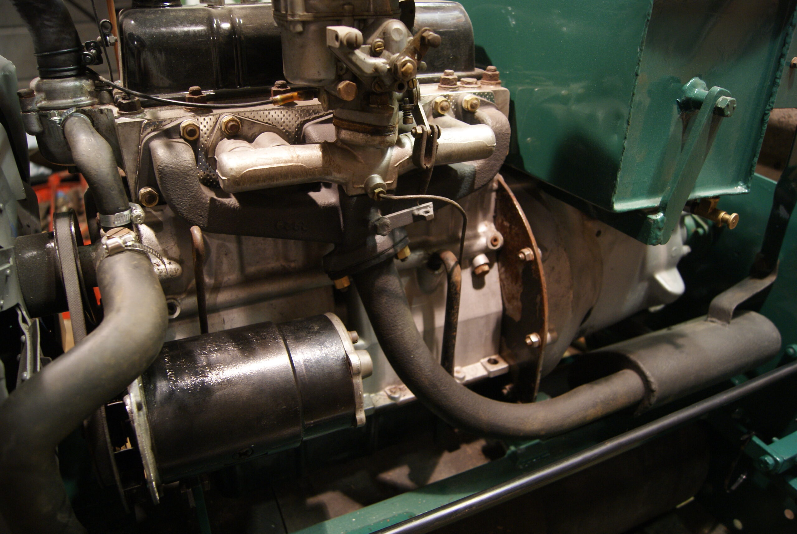
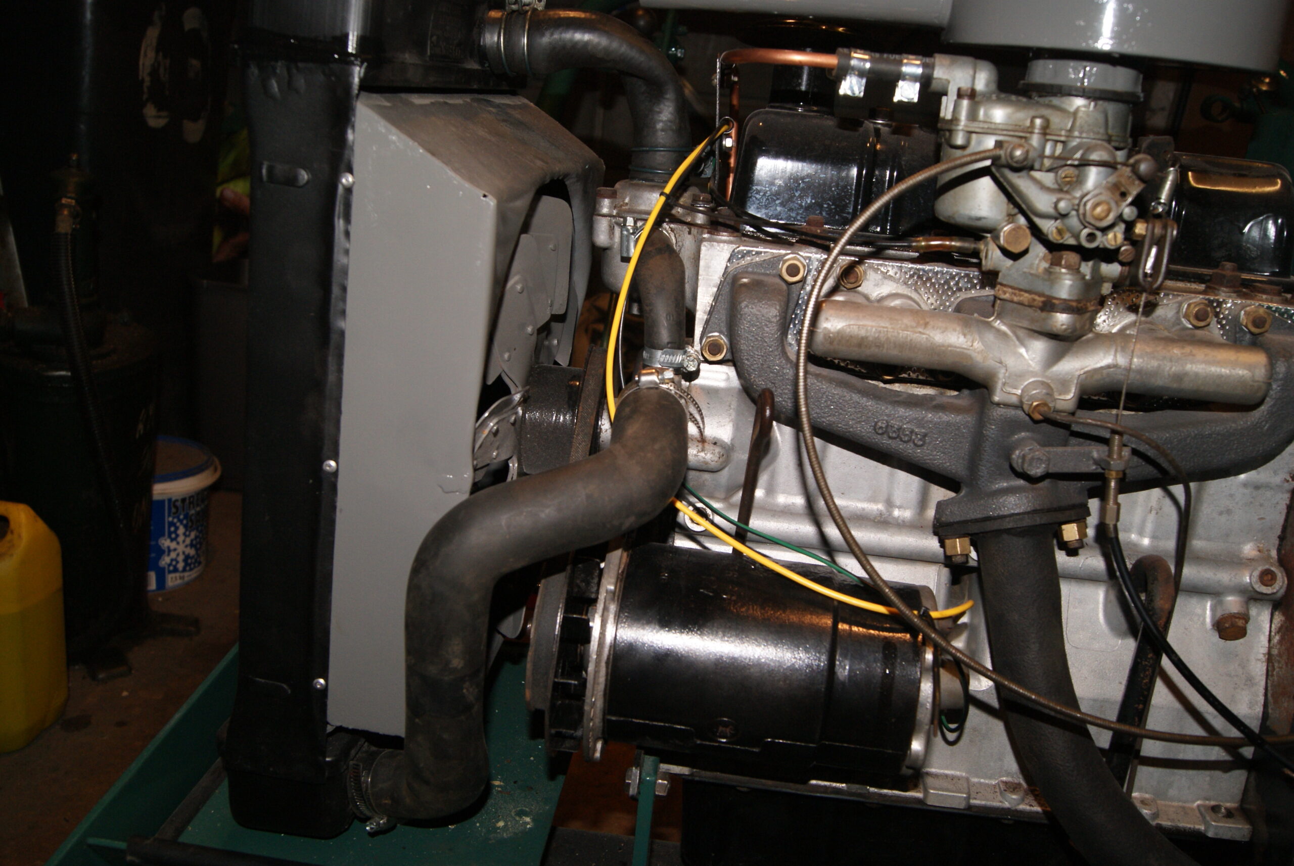
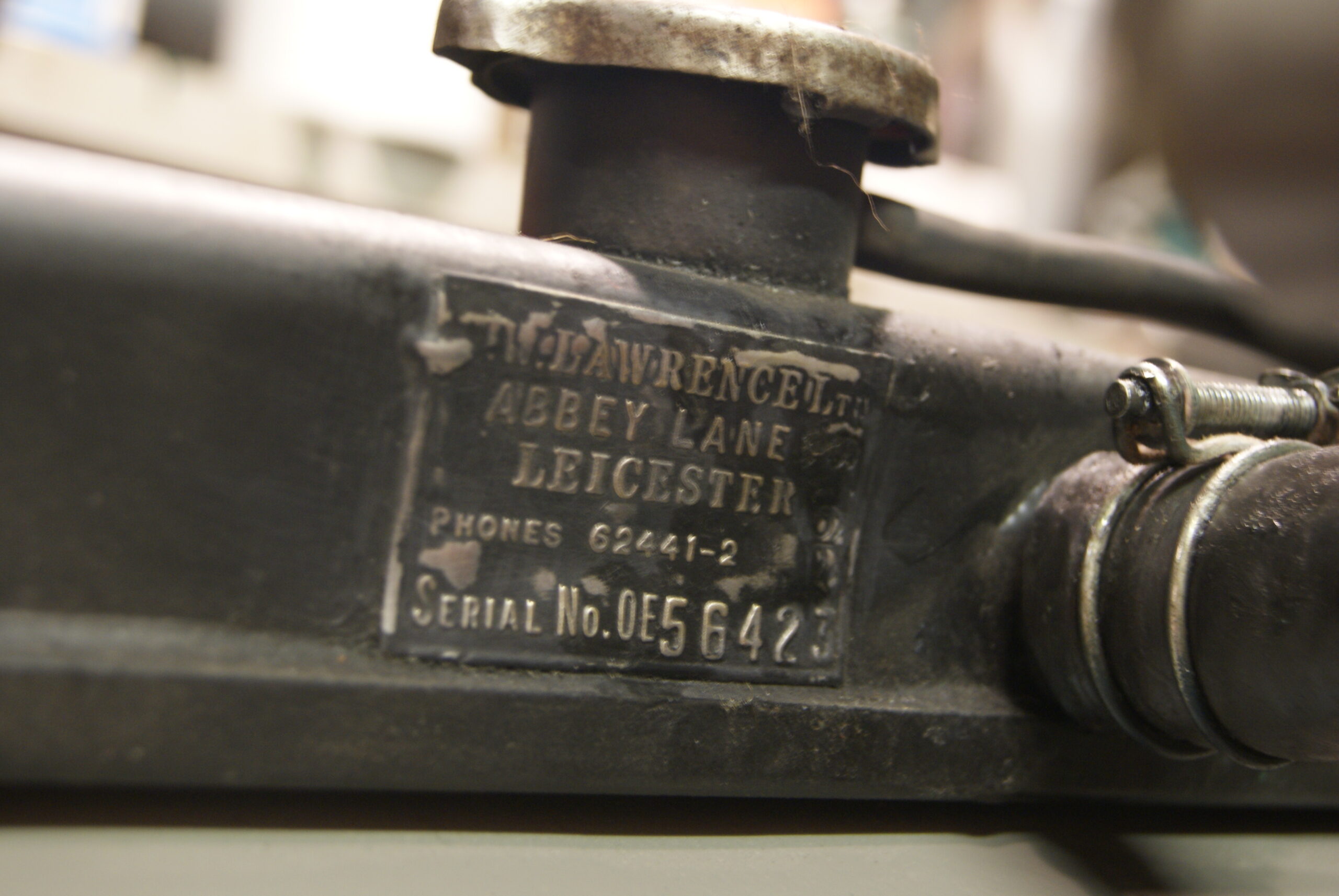
Now that the upper rear crossmember has been painted and refitted the radiator could then go back on. Hoses and hose clips had to be matched up as best as I could find, but I think the result is acceptable- judge for yourselves from the photo’s. I did have some old wire hose clamps that came off a Kubota engine and, seeing as I had to saw the old Jubilee clips off when I dismantled it, I thought they would look the part. I couldn’t get hold of any more, so I had to use some modern jubilee clips on the lower hose but it won’t be visible normally- I’ll try to find replacements when time allows to make it all look “in period”. In a similar vein I wanted to try to preserve some of the mower’s history of repairs during it’s long working life, so when I put the radiator into the repair shop I asked the very nice man if he’d keep the previous repairer’s plate on the top tank; he very kindly did this and didn’t charge me any more for the extra work- top bloke!
The dynamo came back from the repairers yesterday, so this morning it was fitted back on with all spacers in the correct places. The worst one is the lower one facing the radiator and you have to put the bolt in from the radiator side, through the bottom pivot on the dynamo casting, then a steel spacer and then finally try to find the hole in the engine plate with the end of the bolt. You can’t see any of this and it has to be done by feel whilst using your other hand to take the weight of the dynamo. What happens then? The bl***y ‘phone rings, doesn’t it! Curses!
Moving on, the final (lower) rear crossmember was removed and the scraper plate pried off it’s home for many years. Luckily it all cleaned up well apart from one bolt which had to be replaced; the oil leak that had preserved the rest hadn’t quite got that far along, but at least it was an easy substitution. Once repainted it was refitted, which also allowed the front roller adjuster to be mounted again and the front roller and carriage reassembled.
Next on the agenda today will be to source a period-looking battery, then see if I can find someone who can sell me some wiring with the original trace colours to remake the wiring loom. I will also try to locate the original type of Lucas spade connectors with clear plastic insulators so that it doesn’t look out of place or too modern.
You will notice that I have removed the handlebars as well. They will be given the same treatment as they have been painted three or four times in the past and I was also fed-up having to step over them to put everything back together! Also, once I’d cleaned the oil and grease off it was apparent the the place where they met the side frames was harboring plenty of rust, so off they had to come to attend to the rust scabs.
More photo’s again soon once I’ve got a little further.
-
This reply was modified 4 years, 1 month ago by trusty220.
Attachments:
June 14, 2022 at 1:55 pm #39224wristpinParticipantNext on the agenda today will be to source a period-looking battery, then see if I can find someone who can sell me some wiring with the original trace colours to remake the wiring loom. I will also try to locate the original type of Lucas spade connectors with clear plastic insulators so that it doesn’t look out of place or too modern.
Just google vintage wiring and terminals – or similar. Here’s one to kick off with
https://www.autoelectricsupplies.co.uk/June 14, 2022 at 5:08 pm #39228trusty220KeymasterWe have a very good auto electrics supplier in Redditch which has managed to supply all of the terminals, covers and wires to get the job done. I’m going to have to have a re-think on the period battery though. They all seem too large for the hole, plus they start at £200 and that’s plus VAT and postage!
Thanks for the heads-up, Angus. It looks like I’m sorted apart from the battery, and I’ve put Baldrick to work on that problem. He’s not failed me yet, but I suppose there’s always a first time!
June 25, 2022 at 3:53 pm #39272trusty220KeymasterIt seems ages since I updated this post but the time goes so quickly when you’re having fun! Last week was a bit of a disaster with Mrs. Geoff’s car being the first casualty- the electric window regulator broke so I had to stop work to find another and replace it. It’s that or divorce and I know I’m not a brilliant cook!
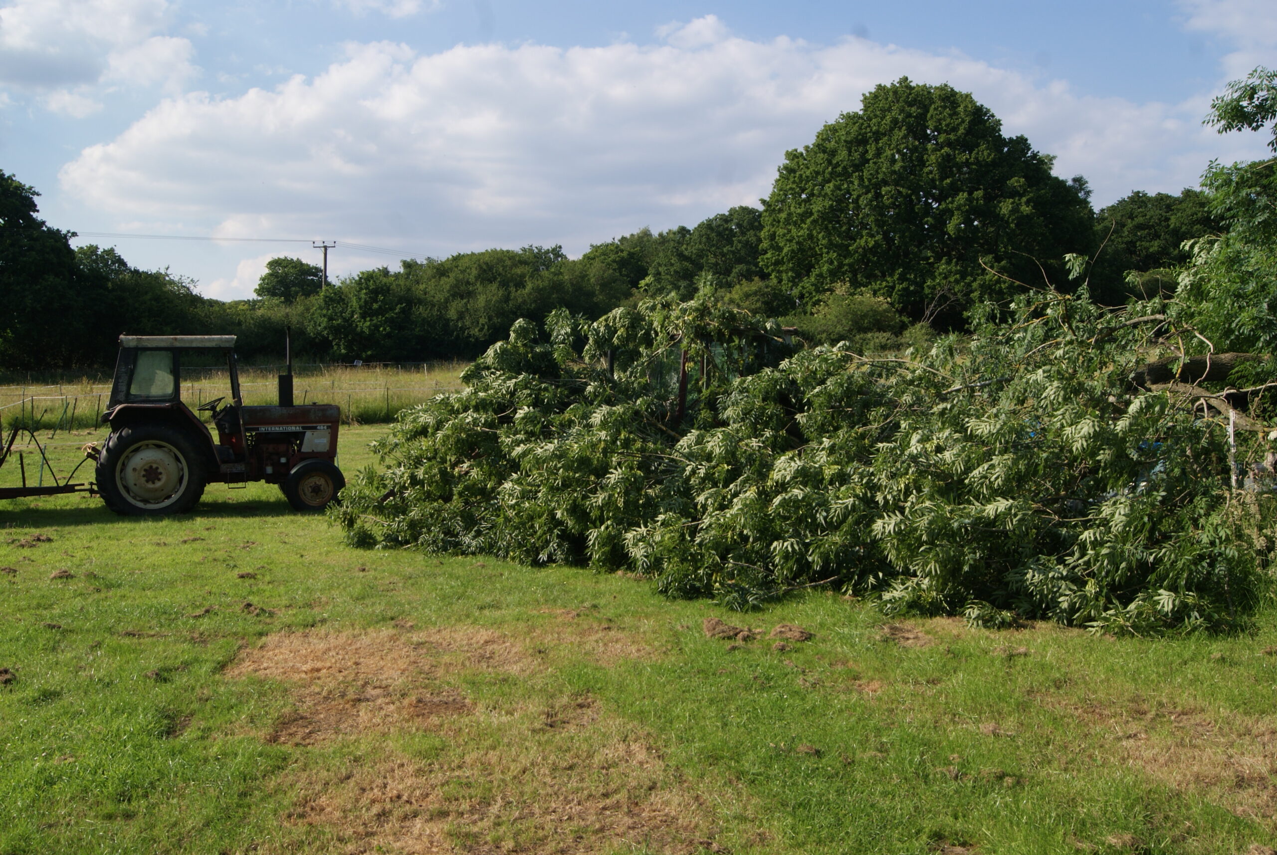
The second disaster was that a huge (and I mean HUGE) branch fell off an Ash tree at the farm just seconds after Mrs. Geoff had walked under it. It completely covered three Trusty’s which were under a sheet and also my International 454 tractor- you couldn’t see any of them when I walked into the field. Luckily the only casualty was a slightly bent wing on the International and a broken side light, the Trusty’s were under the branch but it formed an archway over the top of them. I had a huge bonfire and now have profited about two tons of firewood for when I find that smallholding.
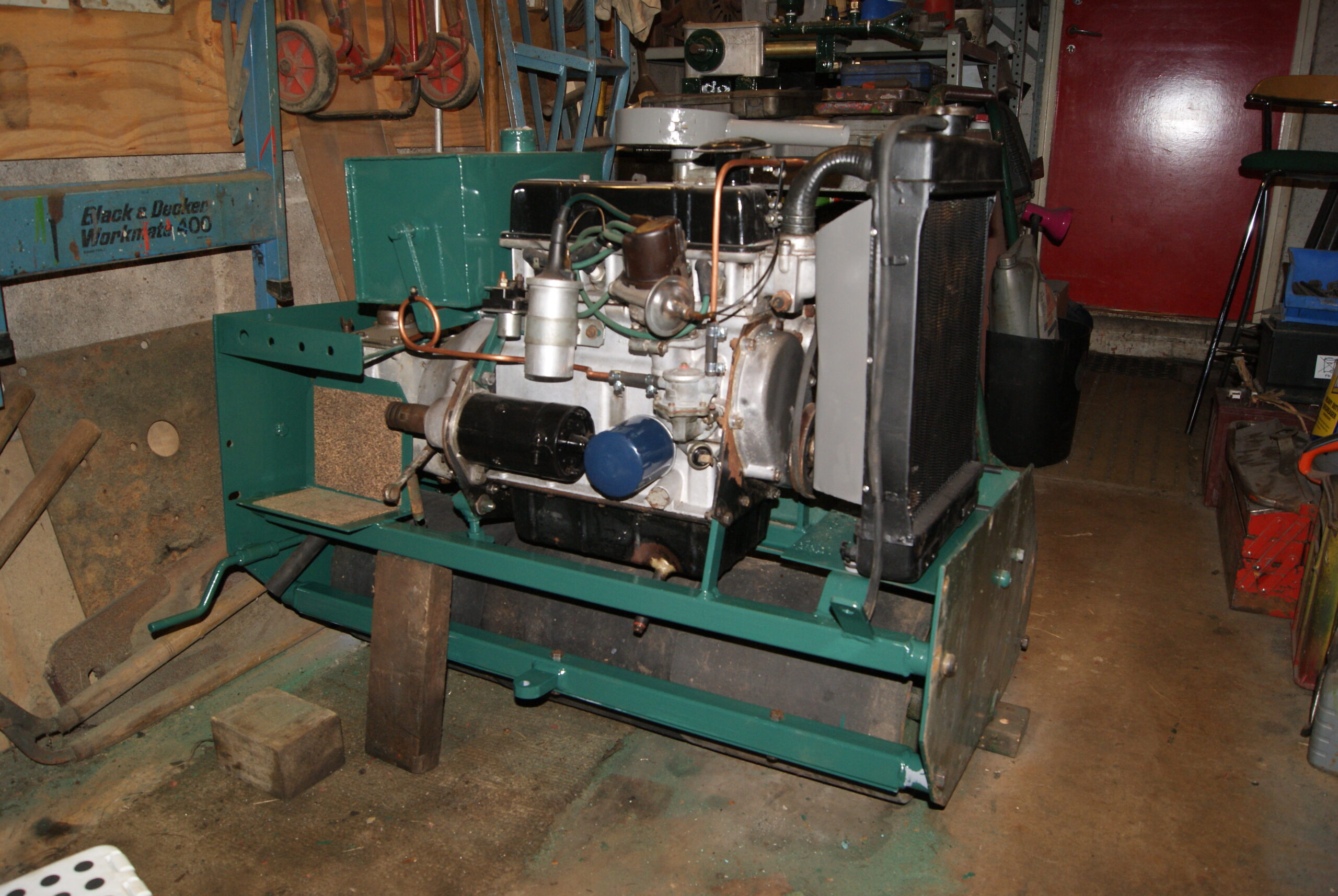
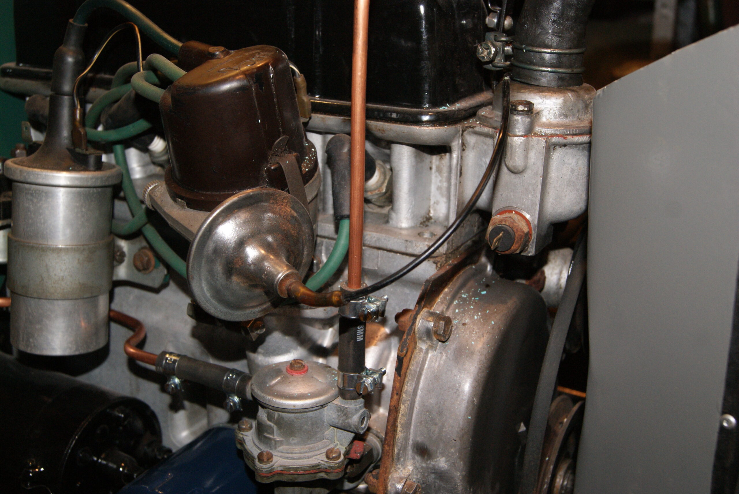
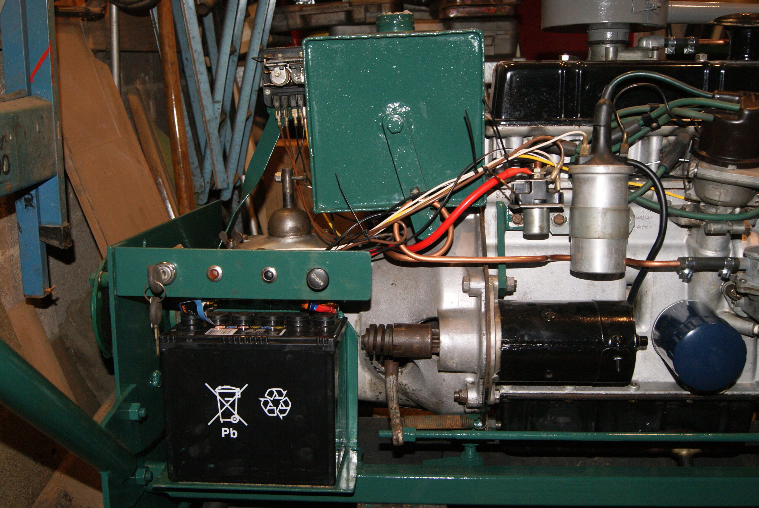
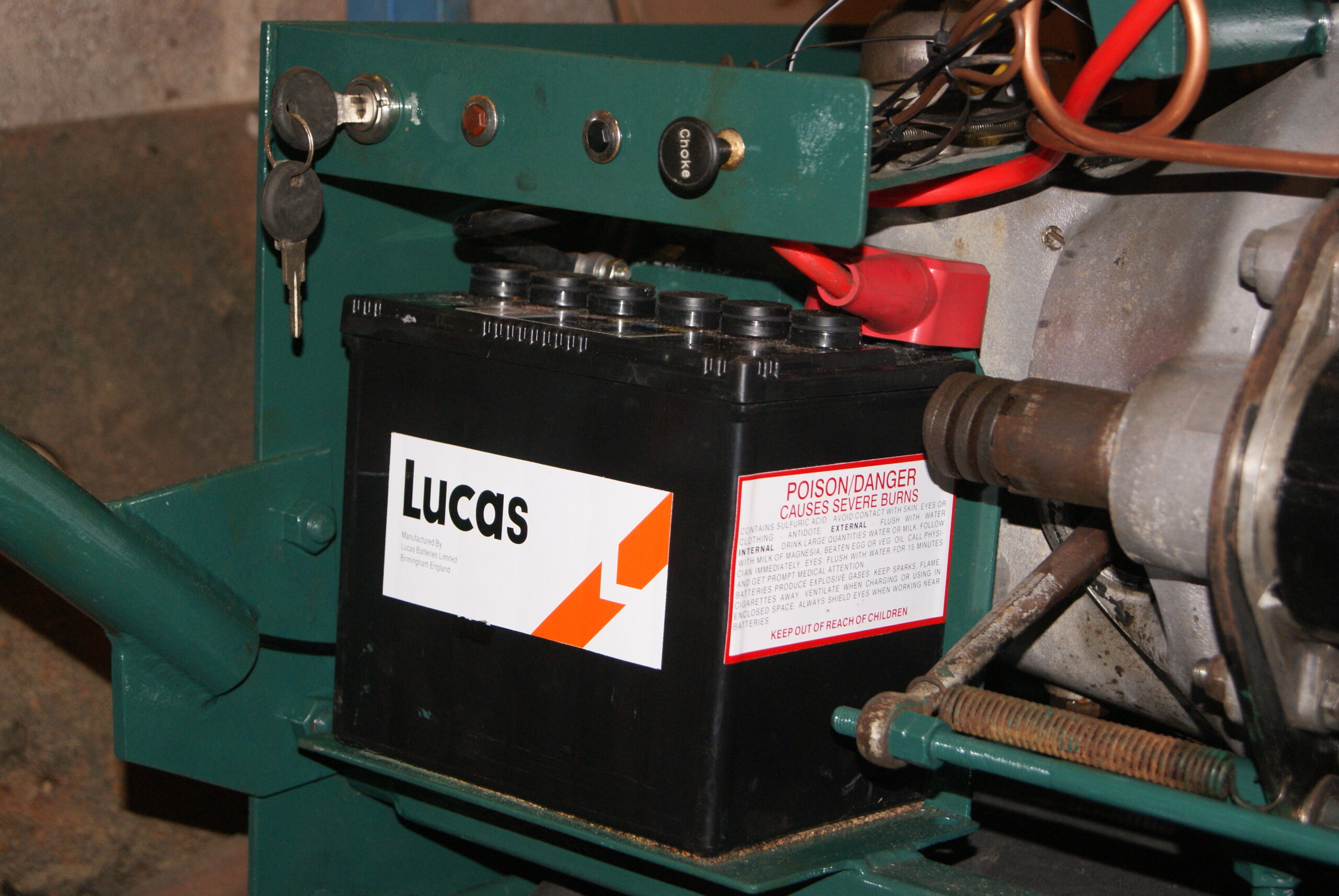
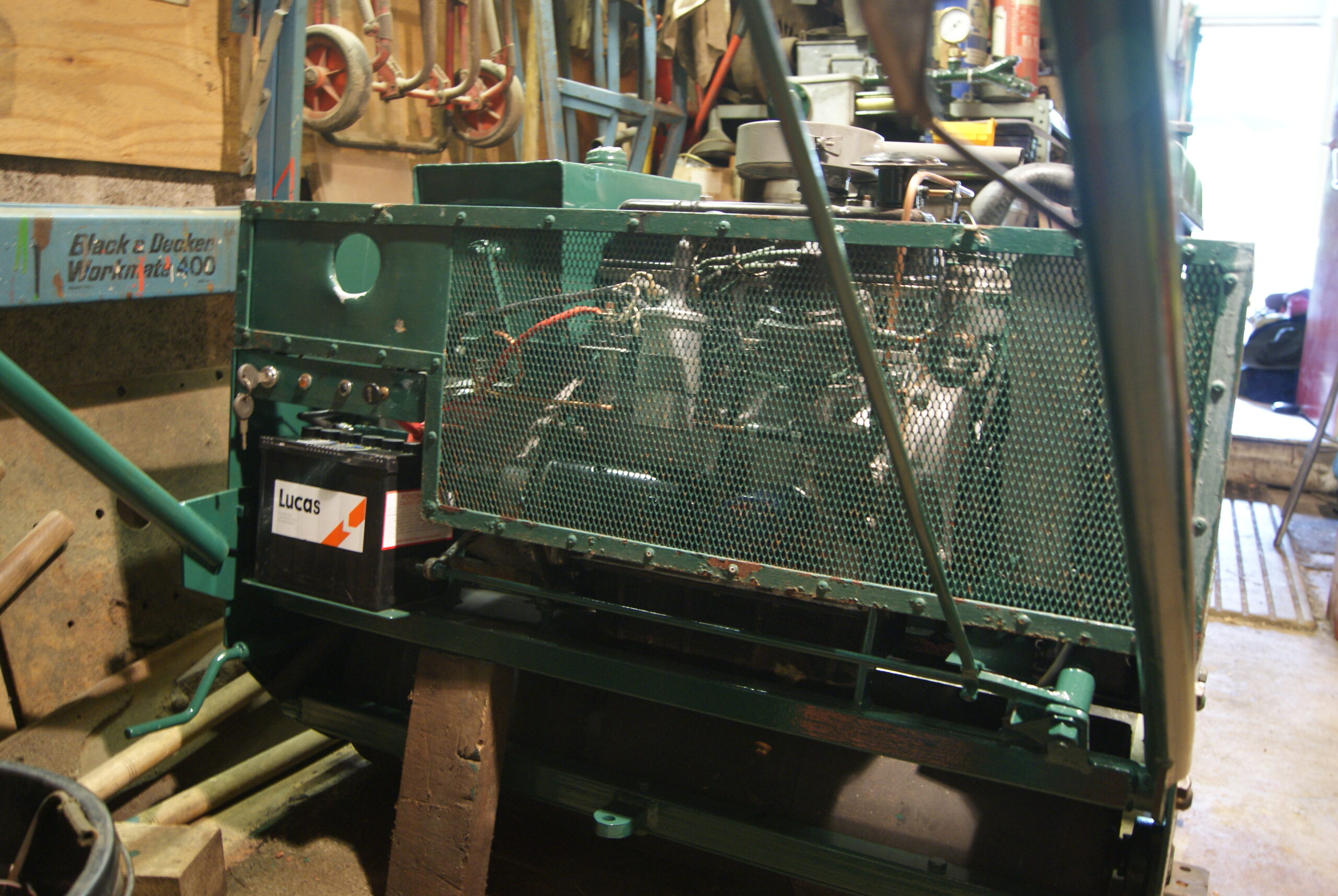
In the meantime…..inbetween disasters I have managed to construct a wiring loom for the Allett; I found the easiest way was to start with the voltage regulator and add each leg individually. You will notice from the pictures that I have left the wires exposed for now just in case, but once I’ve fired up the engine and tried it all out I will bind the wires together in the standard way. Baldrick came up with a battery that fits in the hole and you will see that it has those big pictograms in the worst place possible, otherwise it’s a great fit and has plenty of power. I’ve come up with a solution to make it more “period” and have found some stickers that will cover the offending marks with a large LUCAS logo; the same supplier had some of the small bulbs in stock for the warning lights and so I combined the postage and had them delivered. The bulbs are of a much older design and I was having difficulty finding any but Holden Classics at Bromyard have them- they are called 281 bulbs- so that was another problem overcome.
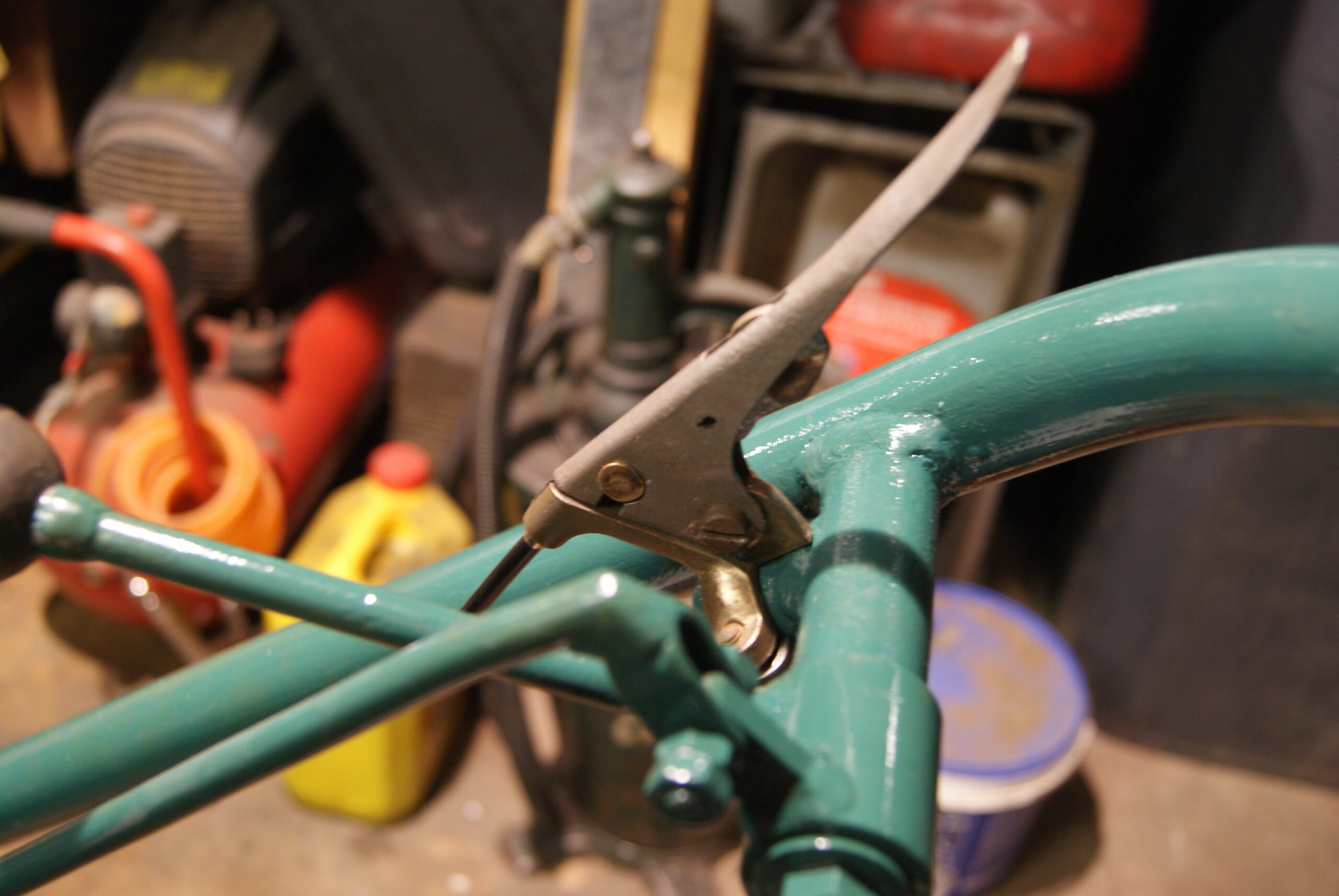
Cables were going to be next on the agenda and I started my search with the local bicycle dealers. Some were about as much use as a fart in a lift but one dealer had cable inner and outer sleeving on a roll together with ferrules and lots of bits and pieces. He didn’t have the same nipples to go on the ends, but I said that I could take them off the old cables and re-solder them onto the new. This is what I did and the machine now has a new throttle cable and cutter clutch cable- the choke cable was cleaned and repaired as I was keen to keep as much of the original as I could save.
For this reason I spent about a day straightening out the cutter clutch lever after de-rusting it with the patio cleaner. It would have been simpler to have replaced it with new, but I want to preserve as much of the original as I can. It was similar to a bicycle brake lever only it has a spring loaded catch that works through a slot in the top. The catch pivoted on a rivet which was peened over on the outside of the lever and so I had to drill it out to remove the catch. A piece of steel bar was inserted into the inside of the lever and used as an anvil to flatten out the creases in the sides caused by bending it. Once that was done I scratched my head to find a way of replacing that rivet- the original was a stepped rivet that gripped the central catch and rotated in the side cheeks of the lever. I opened both side cheeks out to a larger size which would just compress the sides of a roll pin, then opened out the central hole in the catch to give a clearance fit. Once assembled it all works fine so I cleaned both sides up with a file to take off the burrs; now the only quandary I have is whether to fit it underneath like it was on the original photo, or fit it over the top (which is how it came to me) so it doesn’t dig into the operator’s leg when he turns.
Next week should be the first test of the systems on the mower with it’s first firing up since the start. Wish me luck!
-
This reply was modified 4 years, 1 month ago by trusty220.
Attachments:
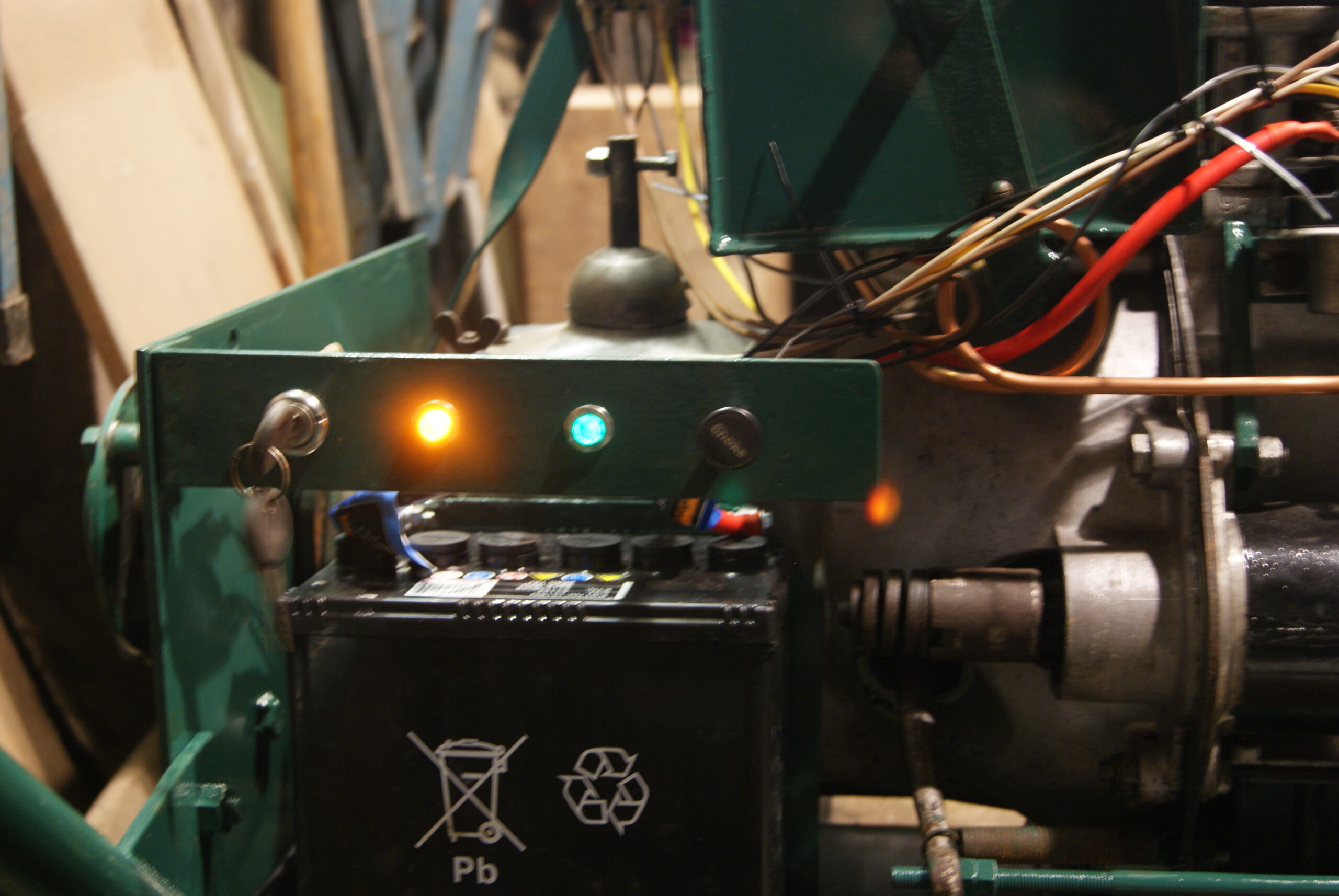
June 26, 2022 at 4:00 pm #39306trusty220KeymasterToday’s work started with a double check of my wiring and then (holding breath) turn the key and it started! The oil pressure light went out but the charge light stayed on- curses! The best thing to do in this situation is to put the kettle on, sit down and think it out. When I was a mechanic I used to stand back and roll a fag to give me time to think, but I haven’t smoked for over thirty years now so the kettle is the go-to choice these days.
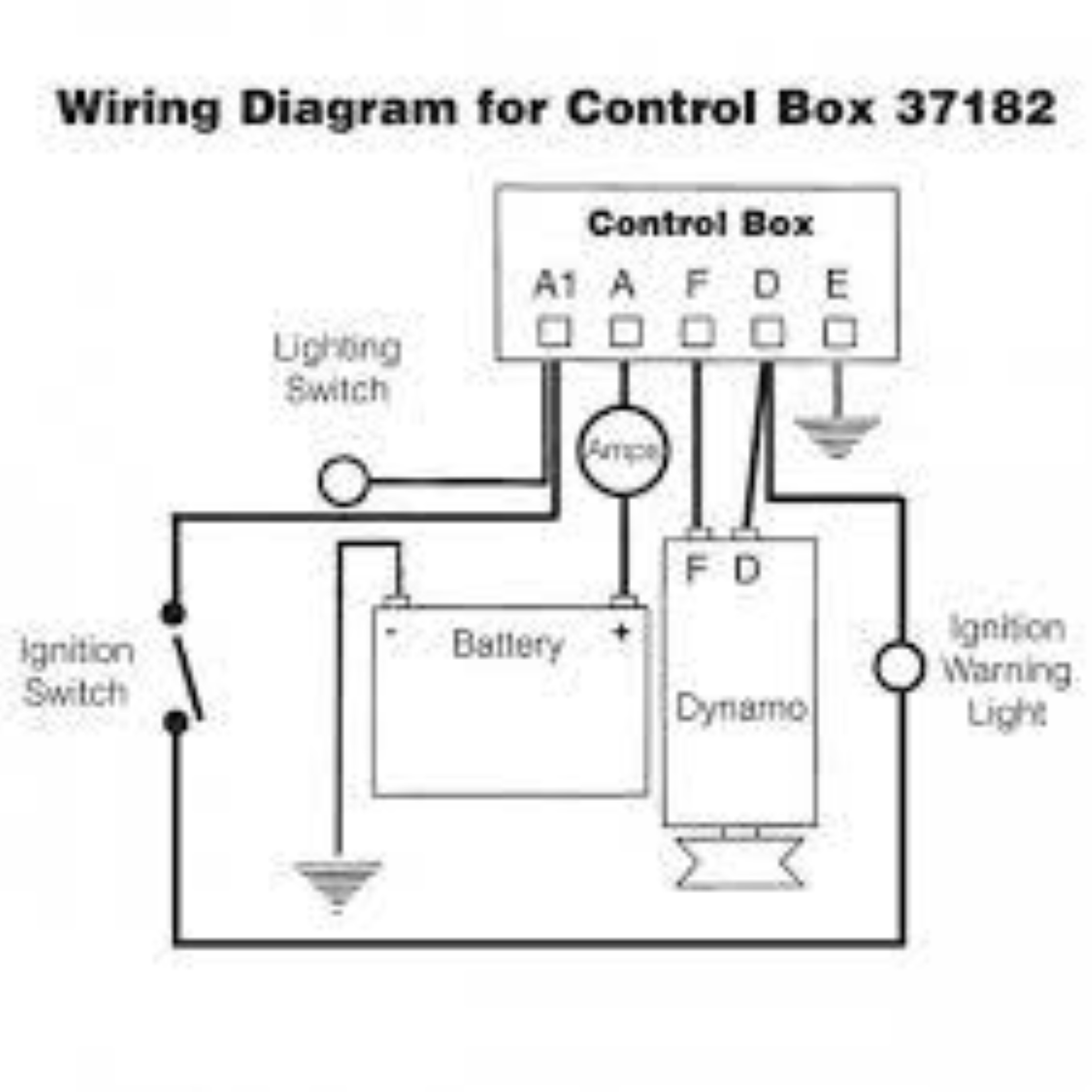
Because it has a dynamo and a separate voltage regulator I was forgetting that the dynamo may need to be “flashed” to polarise the field coils. This is done simply by locating the field connection on the dynamo (normally the small spade terminal marked with a “F”), then taking a length of wire connect one end to the non-earthed terminal of the battery; with the other end of the wire stroke it over the “F” terminal on the dynamo and you should see a small blue spark if you’ve done it correctly. I said non-earthed terminal of the battery because some machinery of this age could be positive earth, in which case you would connect the wire to the negative battery terminal to polarise the field coils. In this instance I’ve wired the machine up as negative earth which shouldn’t present any problems to the next person to work on this in the future.
Next time I fired the engine up the light stayed on, so I gave the solenoid in the regulator a light tap and it freed up and clicked over! Now when I start the engine the light goes out almost immediately but does come on when the throttle is dropped down to slow idle after a brief period of flickering, which is exactly how a dynamo system should work. At slow idle the system is showing 12 Volts with the charging light illuminated, then when the engine speed is increased the light goes out and the system comes up to 13 Volts so I know it’s working as it should. I know that I can tape up the wiring loom now.
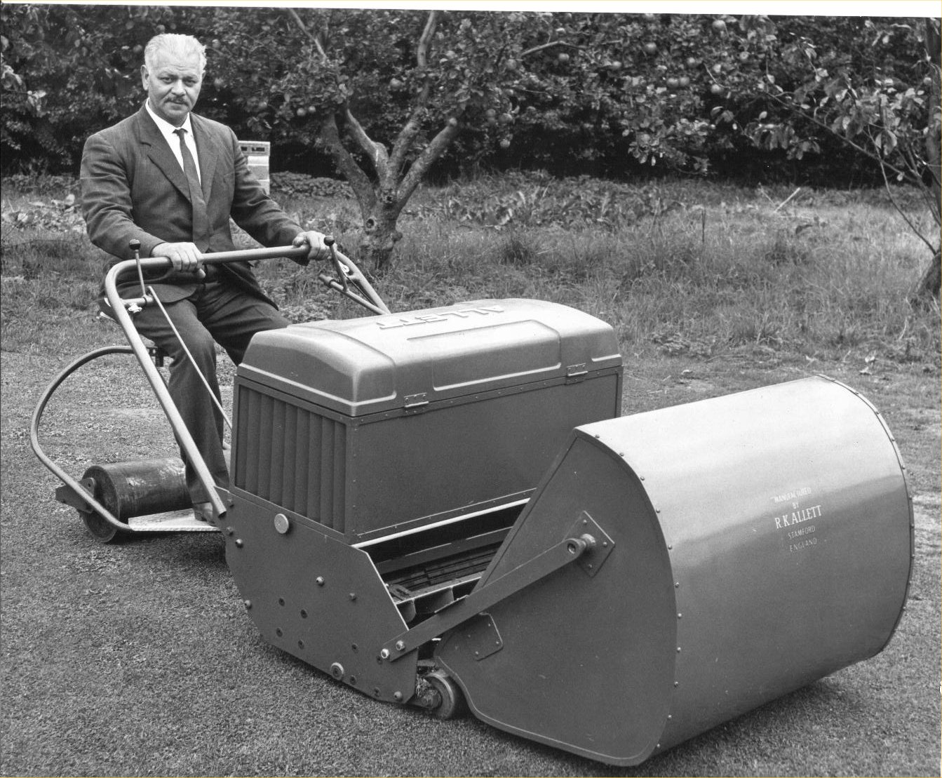
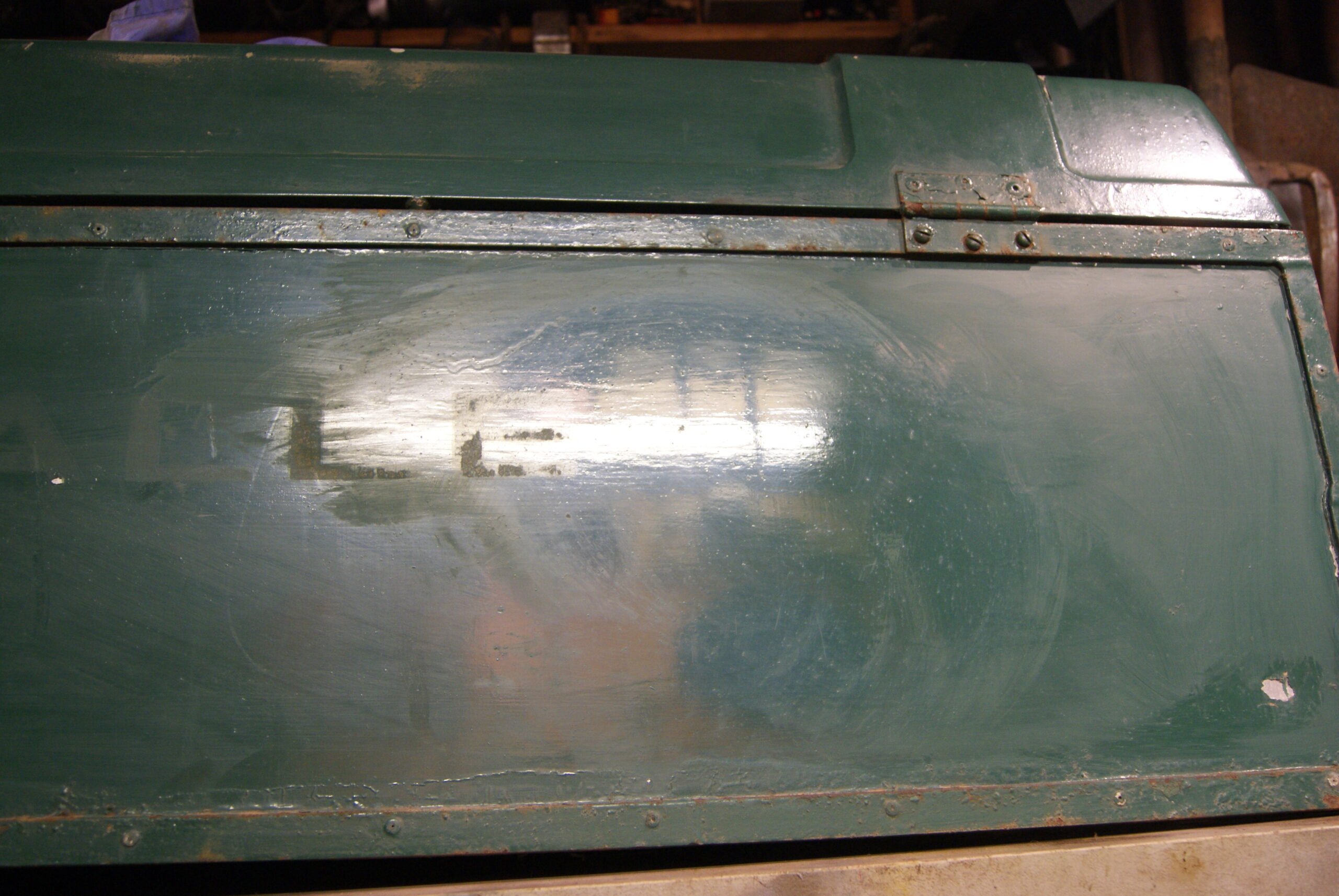
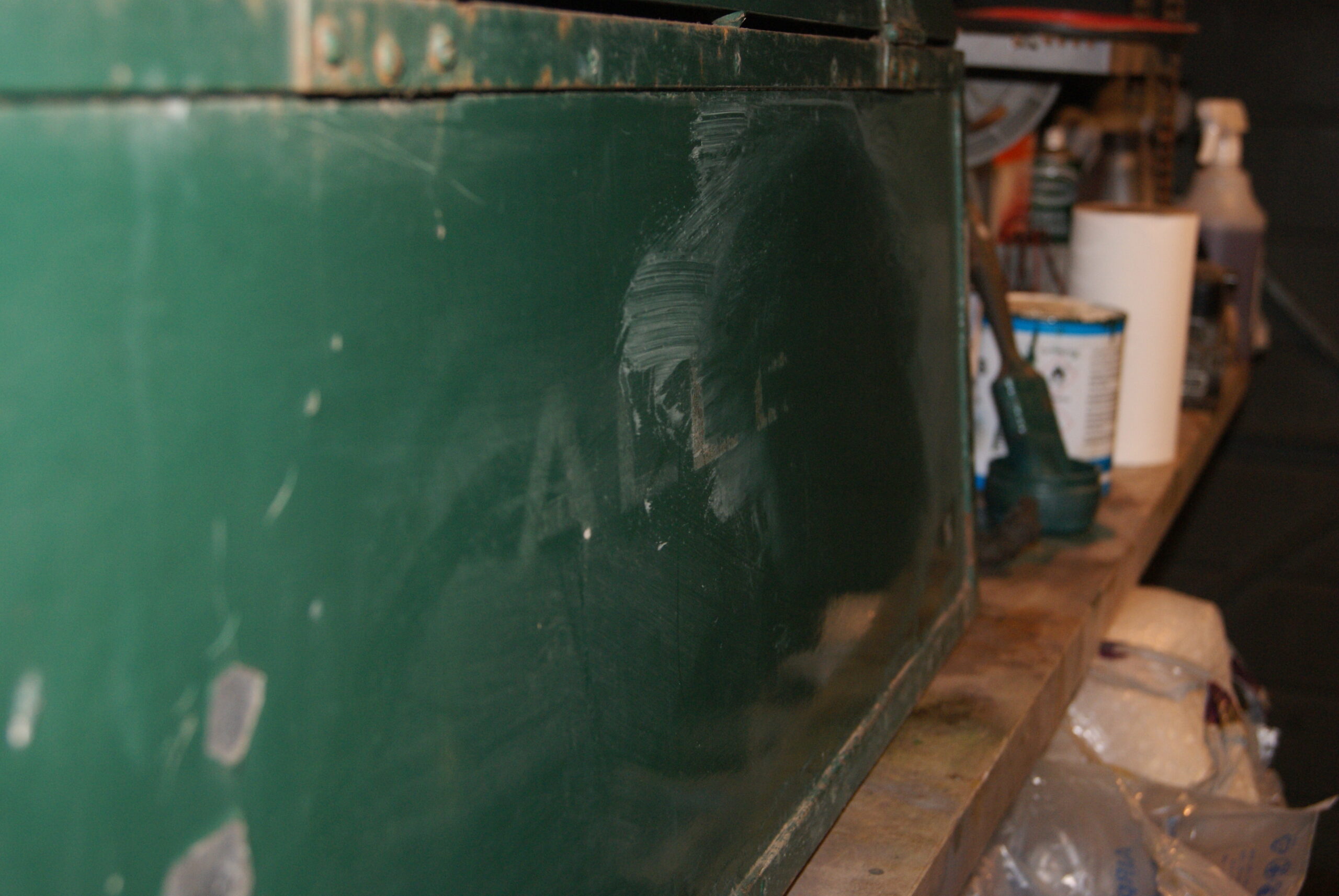
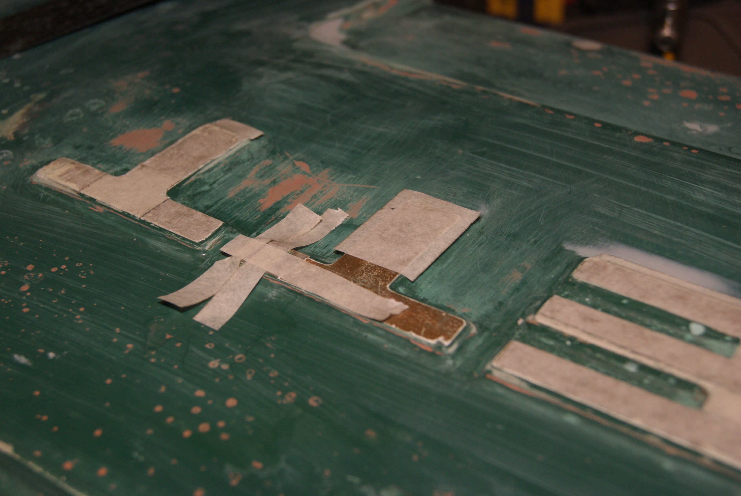
I’ve been tinkering with a few things as well today and got around to disguising the battery with the stickers; I think it looks convincing enough, so I moved on to the engine cover. If you compare the pictures with the original you will see that the Regal did not have the large “ALLETT” logo on the front when it was made, and the factory want it to look as close to the original as possible. Taking a tip off the experts on “Repair Shop” I thought it best to start with something that wasn’t too abrasive, so I tried T-Cut as my first choice. It worked! One of the photo’s below shows the front of the box with the two T’s polished away, leaving the rest of the lettering untouched for comparison. The only trouble is that the paint brush marks are more pronounced now, so I’ll have to do a bit more work on it to see how much more acceptable I can make it without taking the paint off.
I thought you might like to see some pictures of the branch that fell off the tree as well- there’s an International tractor and three Trusty’s under there somewhere!
Attachments:
June 27, 2022 at 7:19 am #39325 charlieKeymaster
Carefully rubbing away layers of paint to reveal lettering is something those restoring ex military vehicles often have to do.
June 27, 2022 at 7:59 am #39331trusty220KeymasterThe difficult bit is finding the right balance between abrasiveness and carefulness! I’m going to try with more T-Cut today but may have to go to very fine wet’n’dry paper then re-polish.
Nobody said it was going to be easy!
July 4, 2022 at 9:11 am #39406trusty220KeymasterThose people on Repair Shop make it look so easy, don’t they? Ever tried doing it yourself?
Trying to match paintwork has got to be one of the most awkward and difficult things to learn, but you can see from the pictures how far I’ve got. The biggest problem at the moment is putting the paint on and then waiting days (literally!) for the paint to harden enough to stand being worked on. That’s something they don’t show you on the telly- you would think it was quite a quick process from some of the programmes, but all these things take time and one thing you can’t rush is how long paint takes to harden.
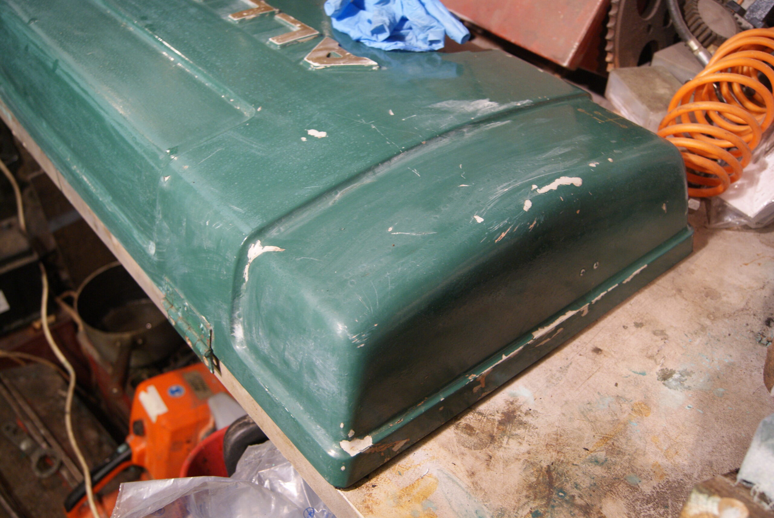
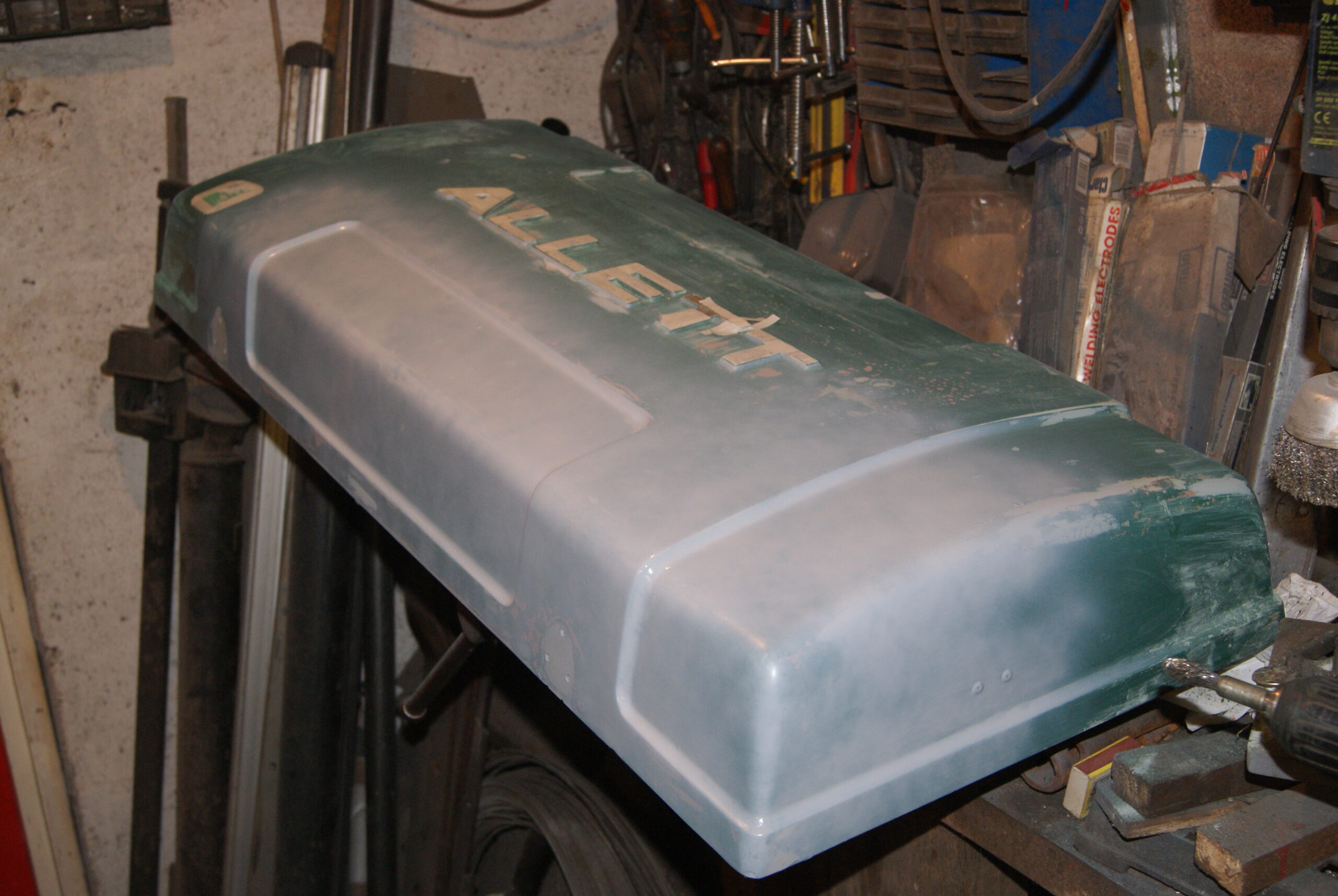
The front panel of the engine cover has come up quite nicely and no trace of the later “Allett” logo that had been applied. The framework is a little more of a challenge as it has plenty of rust patches that need flatting back and it has many places where flatting paste can accumulate, unseen until you turn it over! The fibreglass lid has had the tarbrush treatment in the past with a very thick coat of paint slapped on: this is my main concern at the moment but I’m carrying on with the filling and patching, hoping that when I flat it all down again it will polish up and not show the repairs.
Honestly, it would be easier to flat it all down and repaint so it looks like new, but then that would be my last resort; as I said before, preservation of the original is the aim in this case and it looks achievable at the moment, so press on.
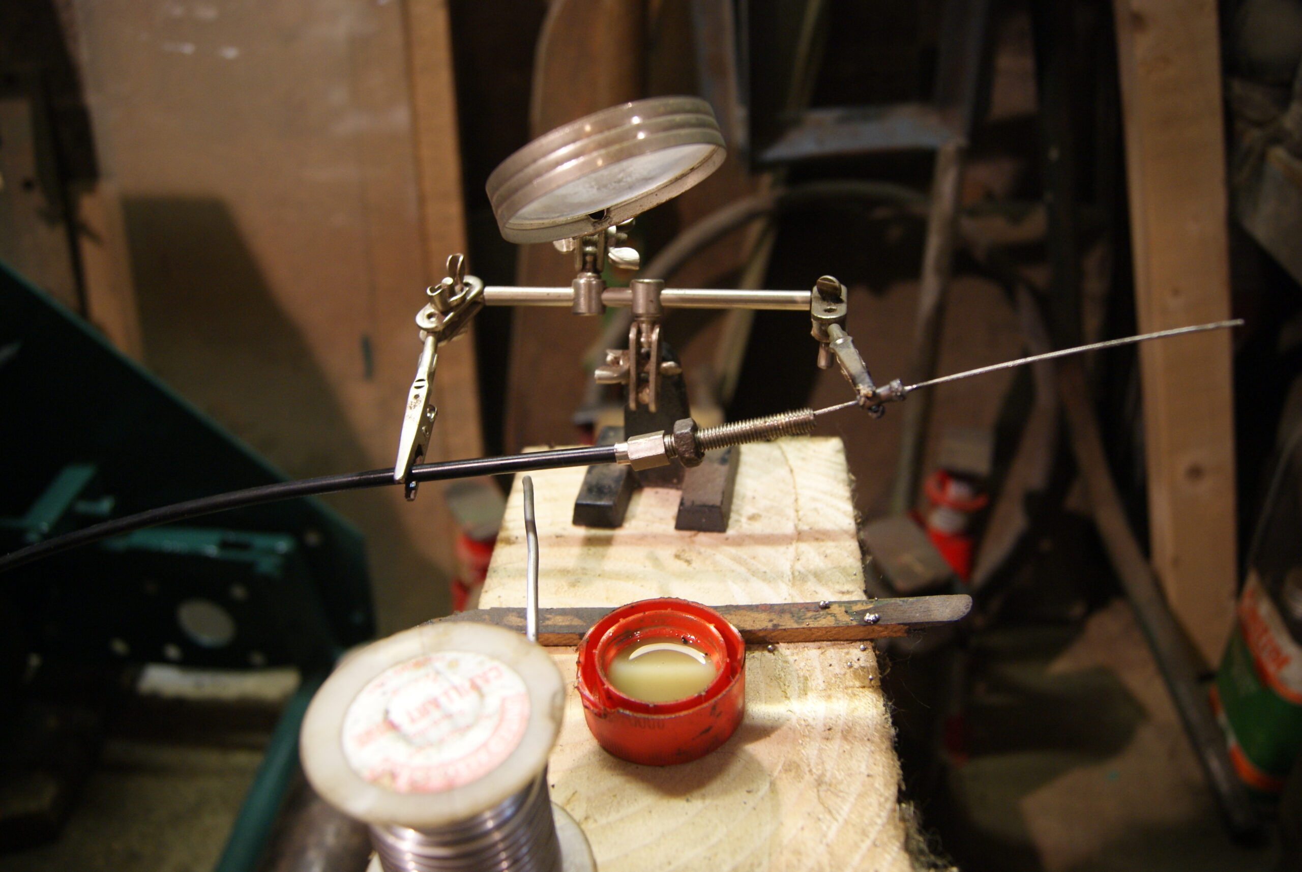
In between coats of paint and filler I’ve been doing some other small jobs such as making up a new cutter clutch cable. You can see from the photo how I do it without burning my fingers or losing half of it on the floor- those “Helping Hands” stands are excellent for holding everything in position whilst you hold the solder and Butane torch to solder it all together. I’ll tackle the cutter clutch and chain drives this week as a diversion from watching the paint dry!
Have a good week!
Attachments:
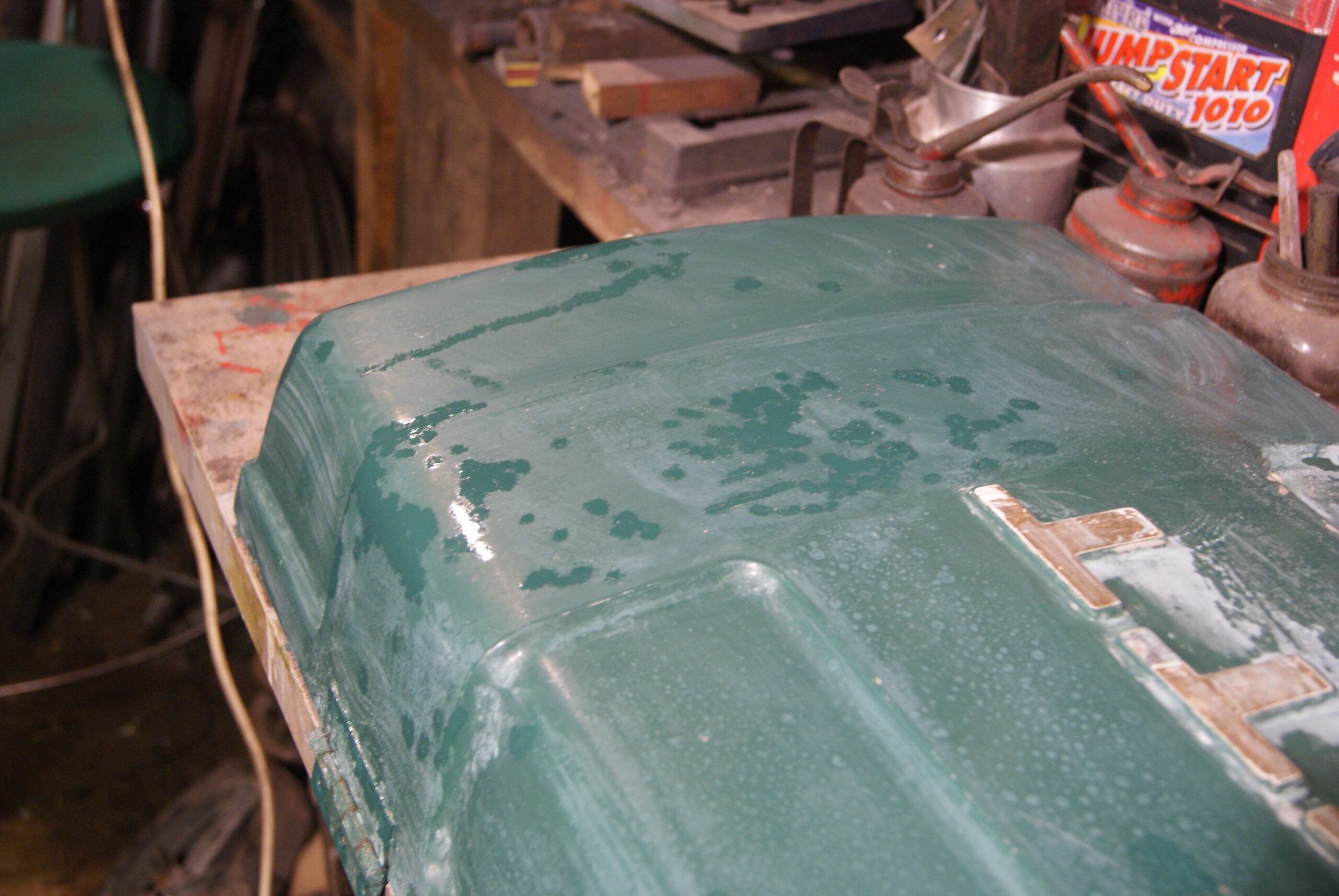
July 17, 2022 at 1:17 pm #39458trusty220KeymasterIt really has been some time since I updated this story but I haven’t been slacking. The main piece of news is that I’ve had a minor disaster with the fibreglass lid; it had many dents and scratches which I was filling with stopper (a very fine filler used for small imperfections) but when I went to flat them back to blend them in with the rest it proved impossible without rupturing hundreds of microblisters. It looks like somebody in the past has repainted the lid with a high-build primer/filler; this was coloured orange. The green paint was applied over the top of the orange primer but because the surface preparation was not good enough at the time, the primer/filler has lifted in hundreds of blisters and lifted the green topcoat with it. What this meant in this case was that when I flatted it down it left lots of orange spots in the green paint- not a good look!
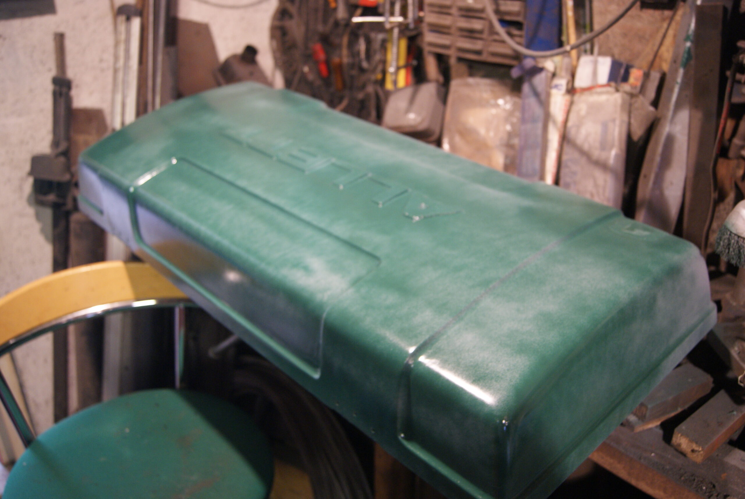
I have now flatted it all down, filled the blemishes and it has had a coat of grey primer and the first coat of green. I’m currently waiting for it to dry.
Another part of the job involved preserving the lettering on the top which is applied to raised pieces of fibreglass. The letters themselves are cut out of plastic and glued on, so I wanted to try to preserve them as best as I could. Masking tape was applied to each one in turn, then carefully cut around with a very sharp scalpel to leave a close cut mask on each letter. This seems to have worked fine so far, but I also had to make up a piece to repair one of the letter “T’s” which had become broken; a piece of 10 thou plastic card sorted out the job, secured with epoxy adhesive. When finished I’ll take off the tape and give the letters a light coat of gold, then rub it back with fine wire wool to age it.
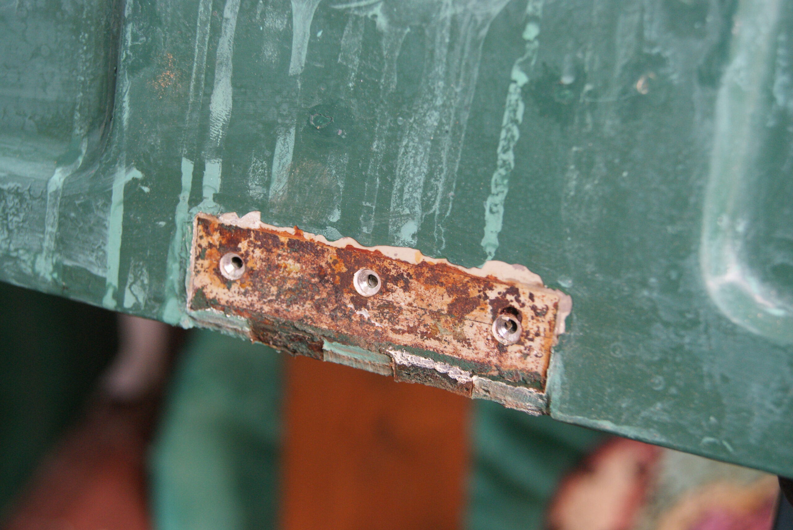
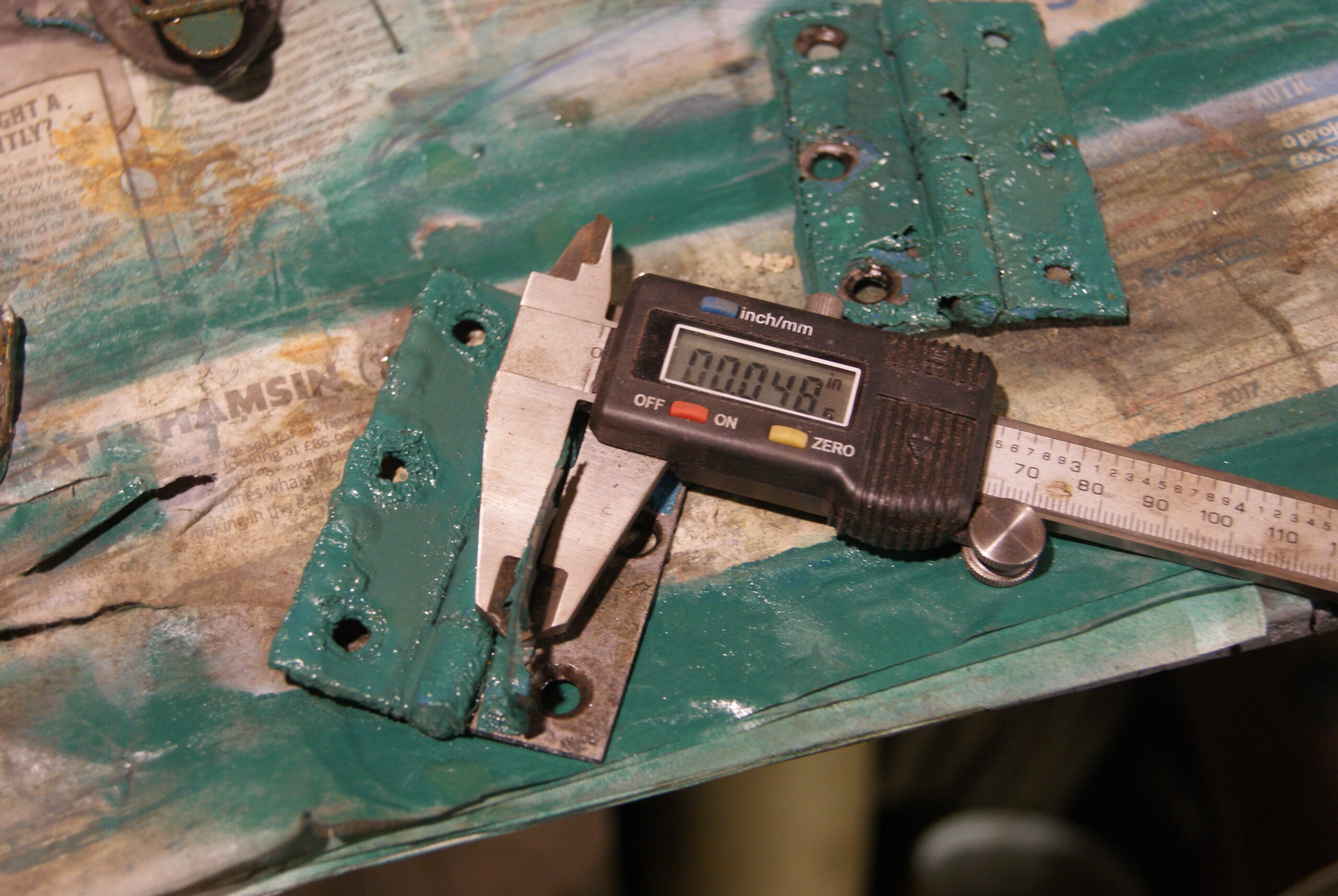
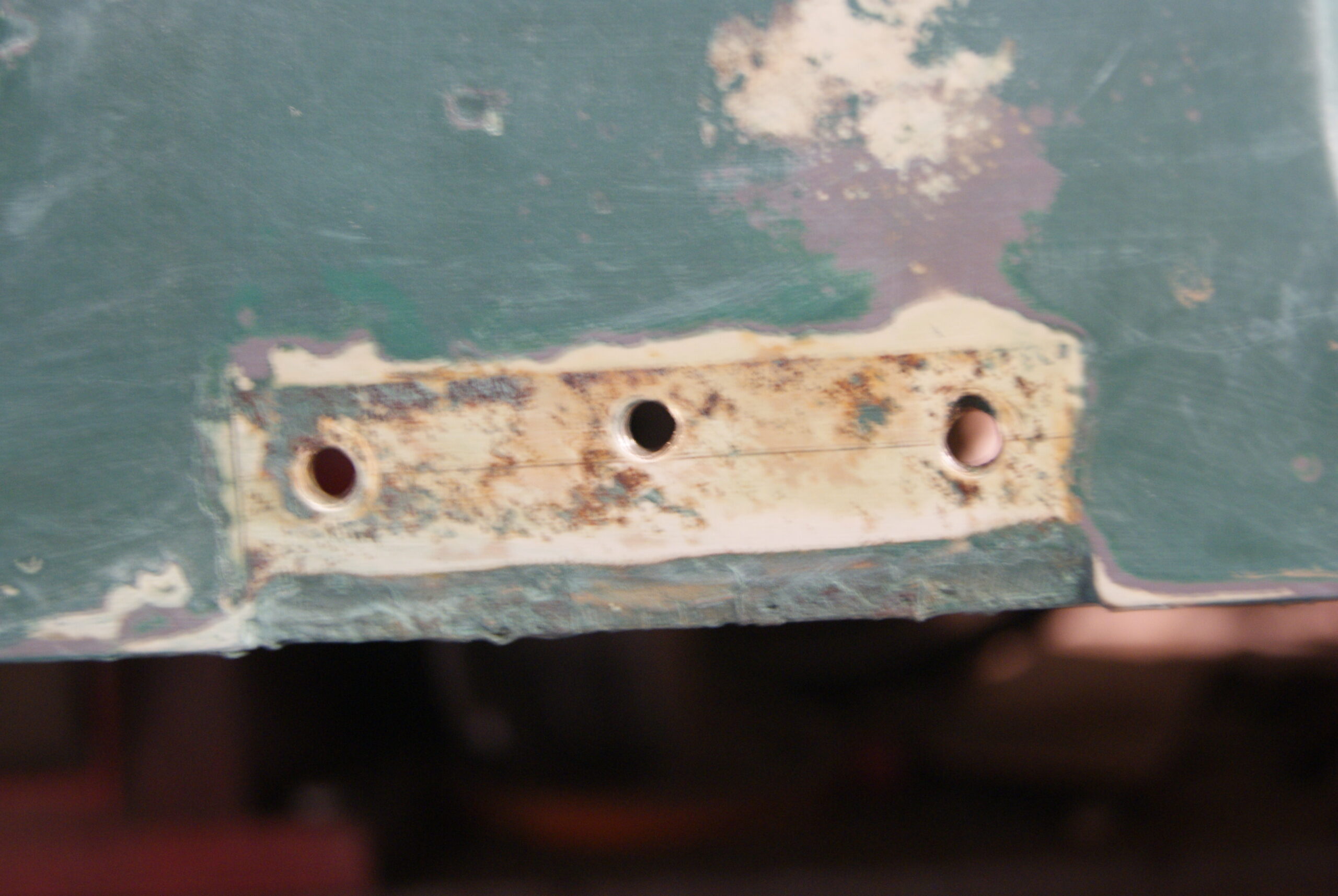
To give some idea of the thickness of the paint I have included a photo that I took whilst stripping the hinges off- the screen on the digital vernier is set to imperial and it is showing just under 50 thou. I just couldn’t leave the metalwork looking like that, it looked awful! I’ve included another photo of the place where the hinge was mounted and you can see the original pencil marks that the builder used to mark out the position of the hinges. I wonder how long before these see the light of day again.
The cylinder and bottom blade will be coming back tomorrow so that will be another part finished. Unfortunately I couldn’t re-use the cylinder bearings as one was showing signs of wear and the other broke when the factory people tried to remove it from the cylinder shaft. They are still available but the modern equivalent has the four holes tapped 1/2″ UNF, whereas the original used 1/2″ BSF, so that means I’ve got to wait for some 1/2″ CSK screws to arrive.
Oh well, we’ll get there one day!
Attachments:
-
AuthorPosts


- You must be logged in to reply to this topic.