Forum Replies Created
-
AuthorPosts
-
October 24, 2015 at 11:32 am #14942
 vhgmcbuddyMember
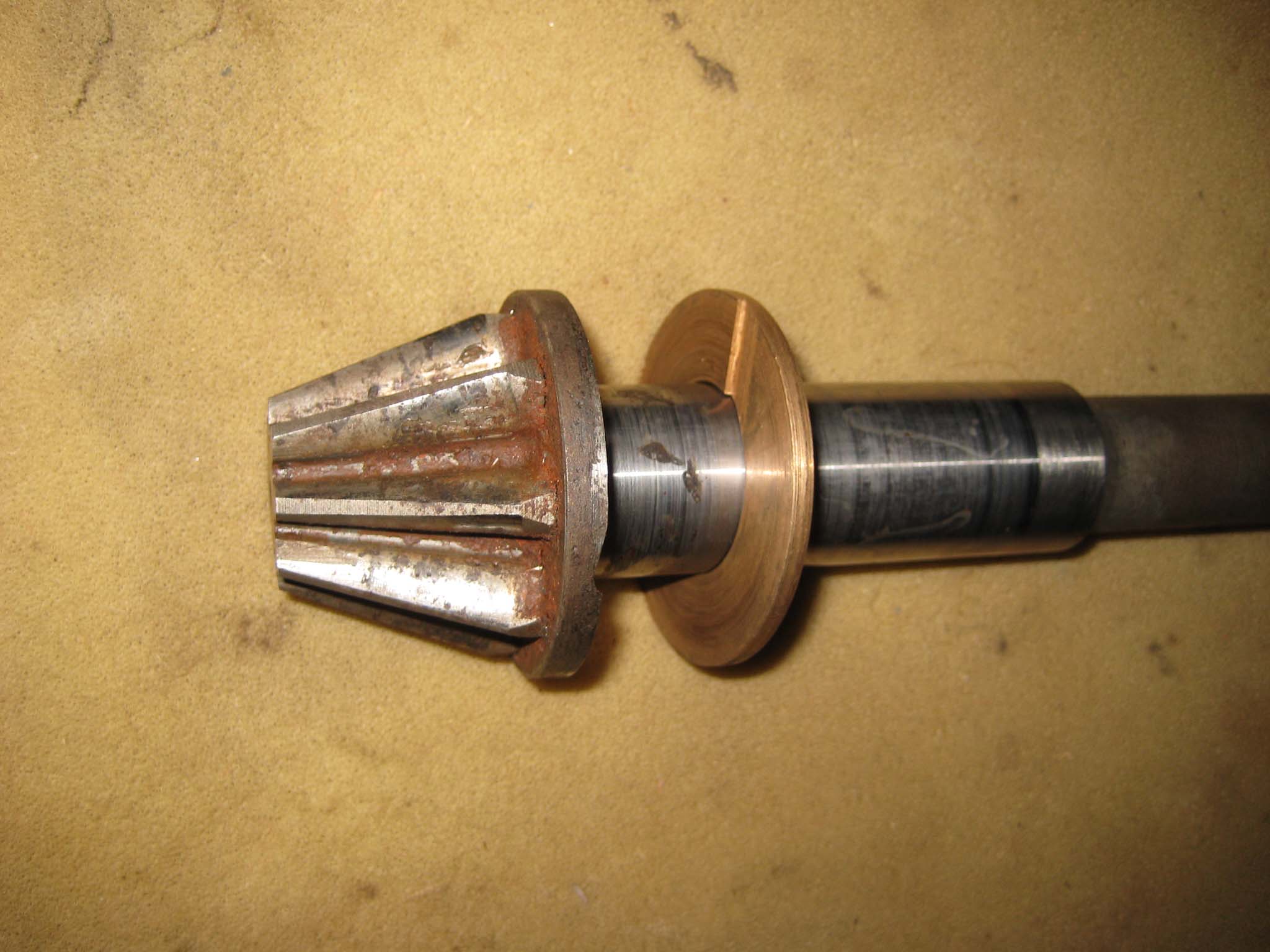
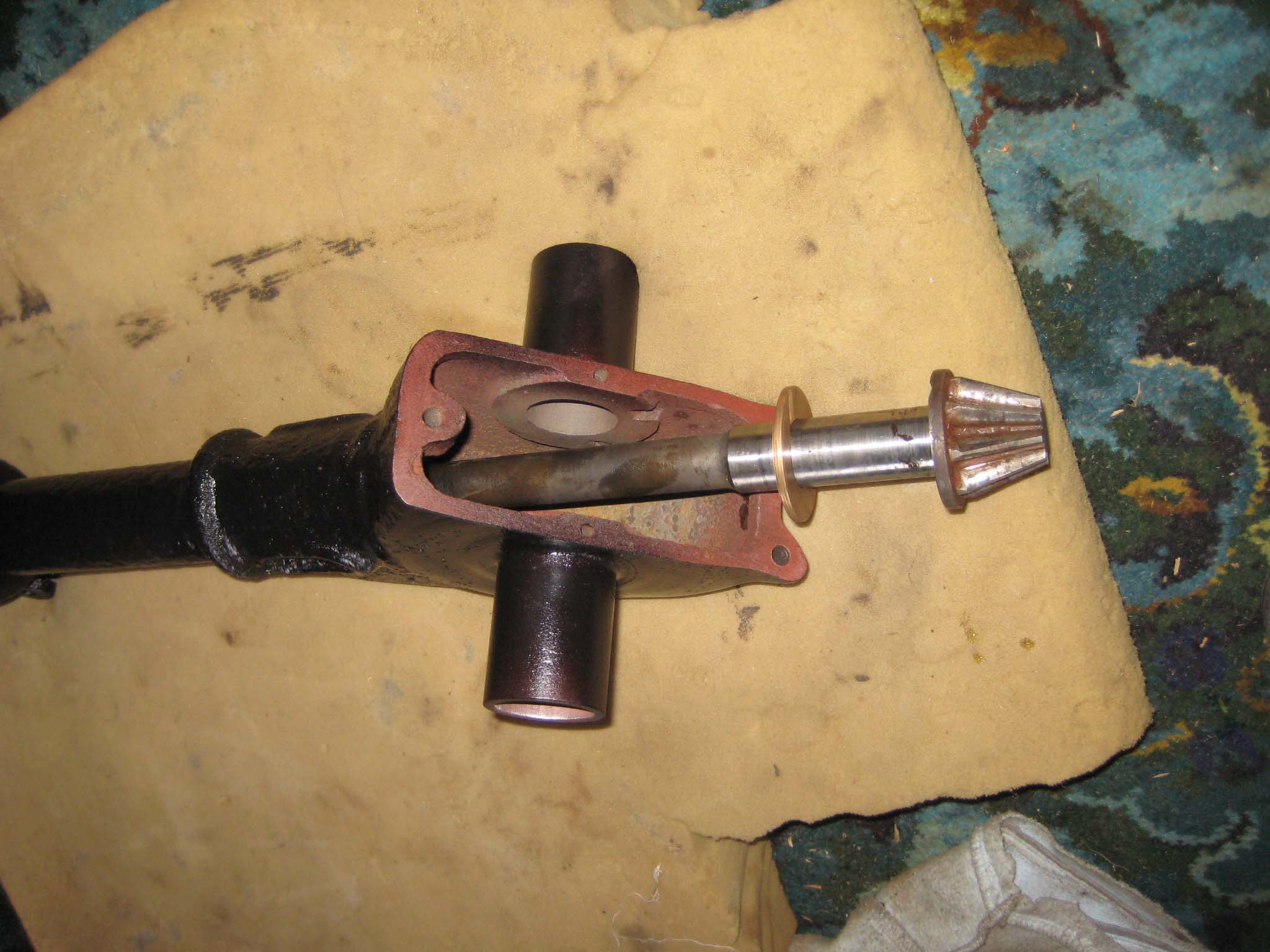
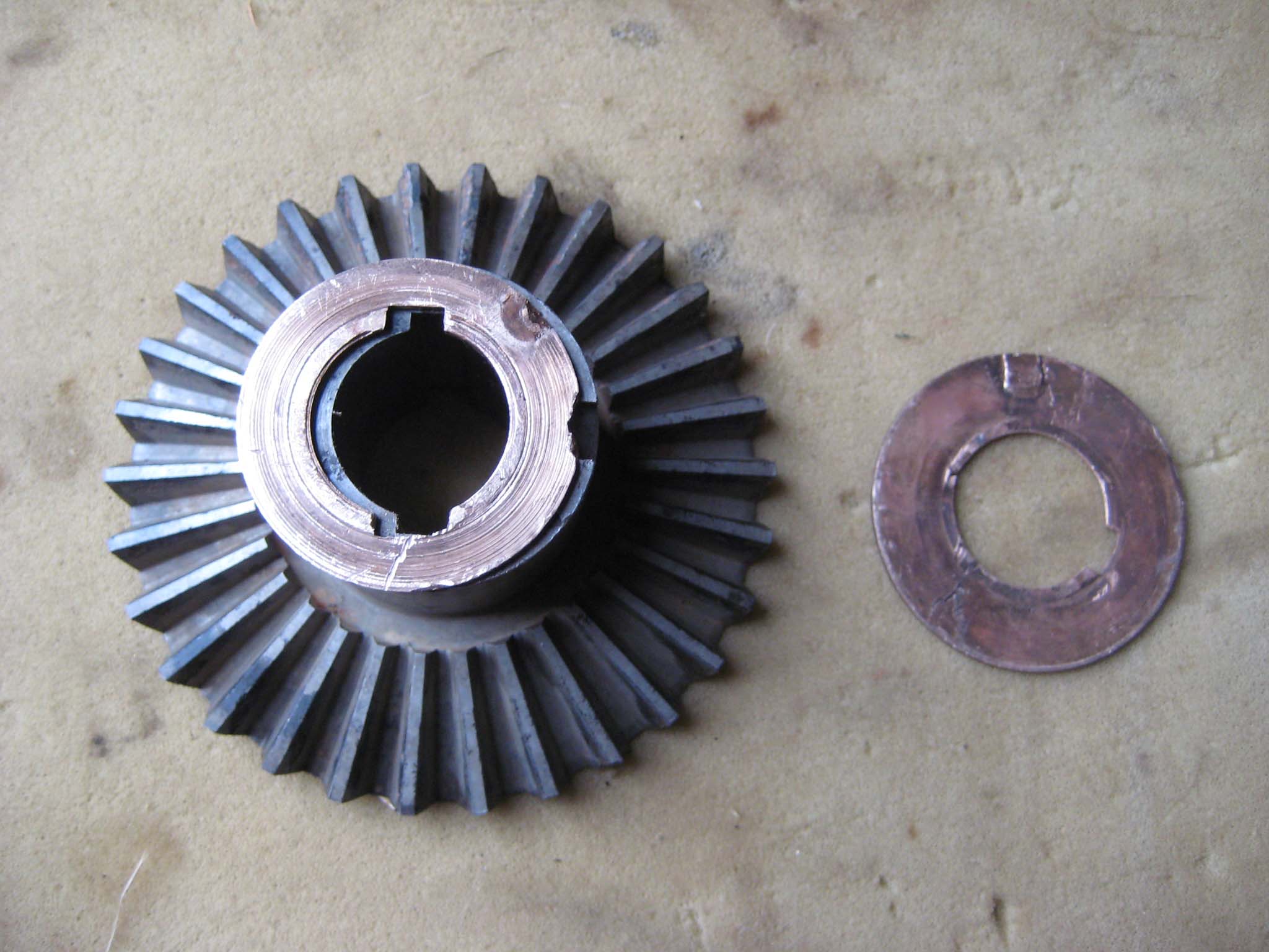
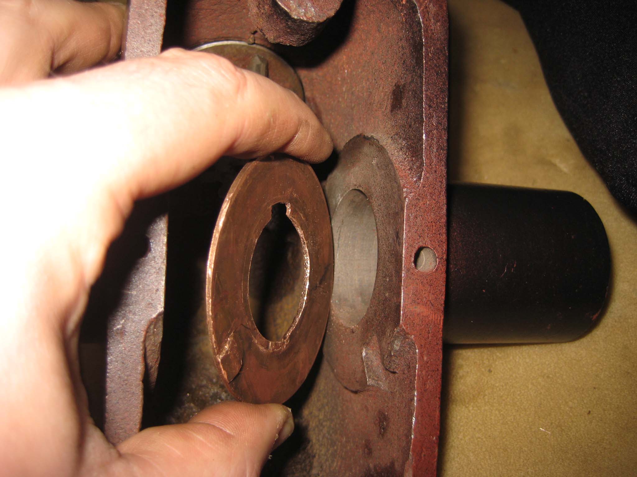
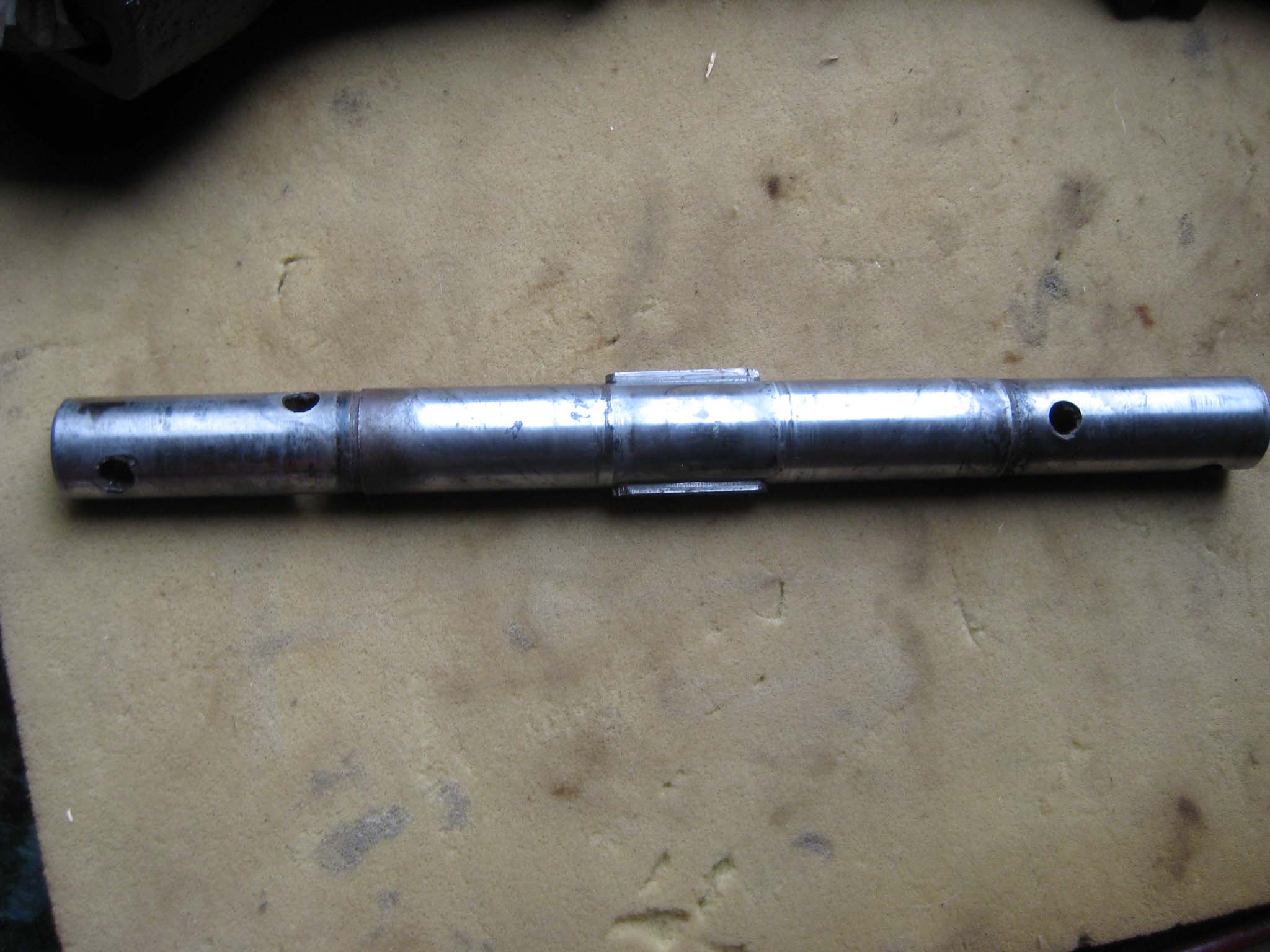
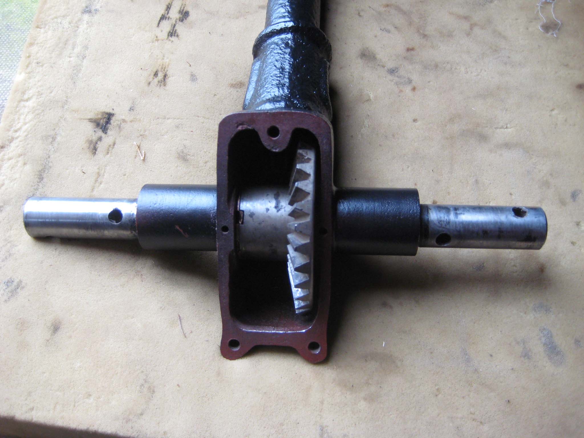
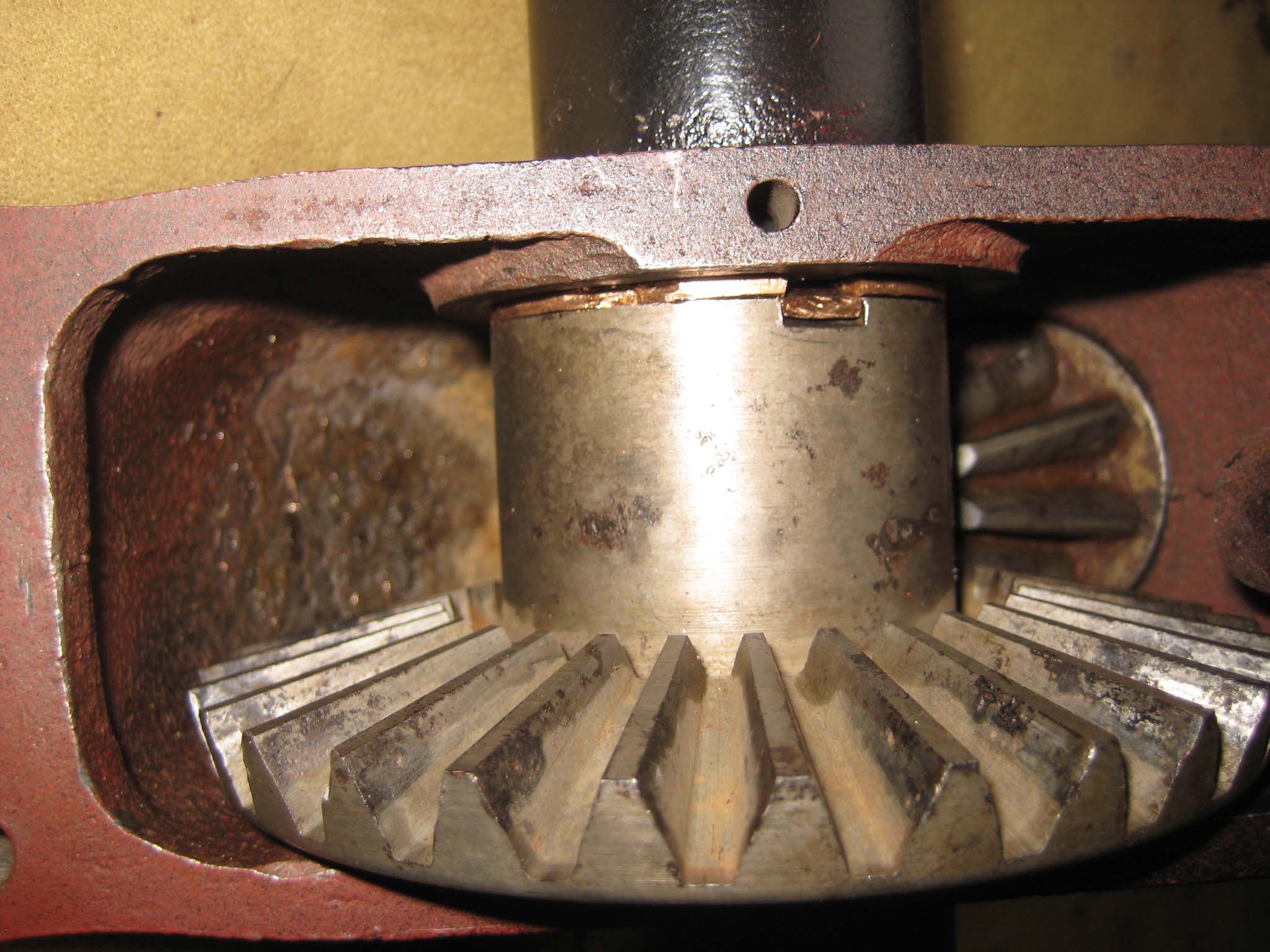
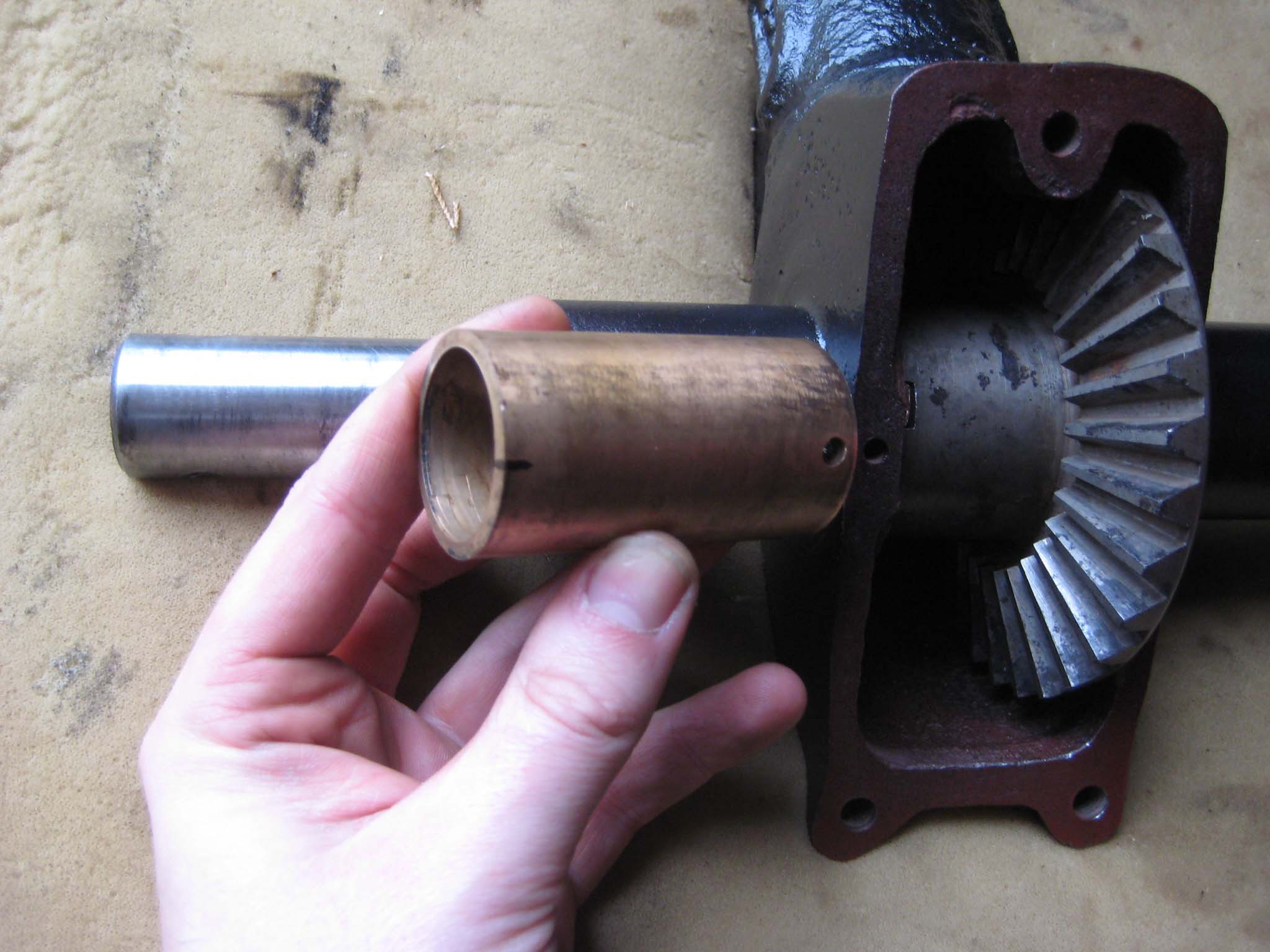
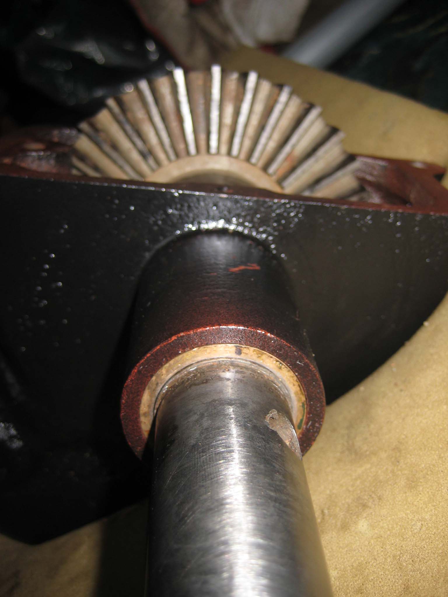
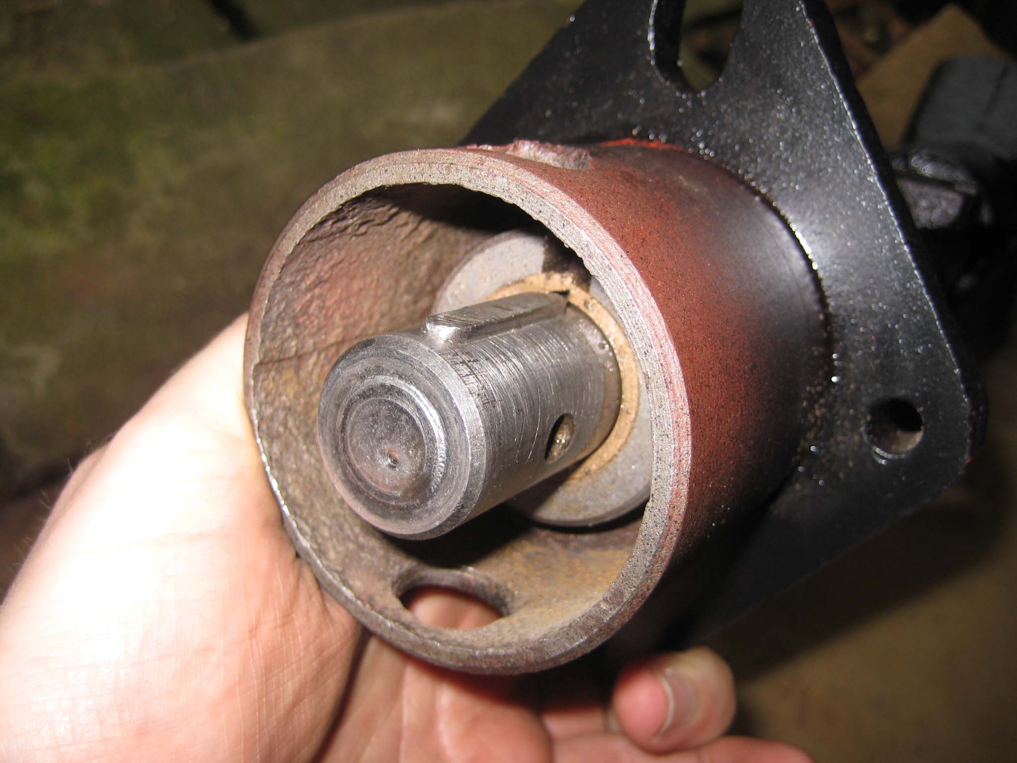
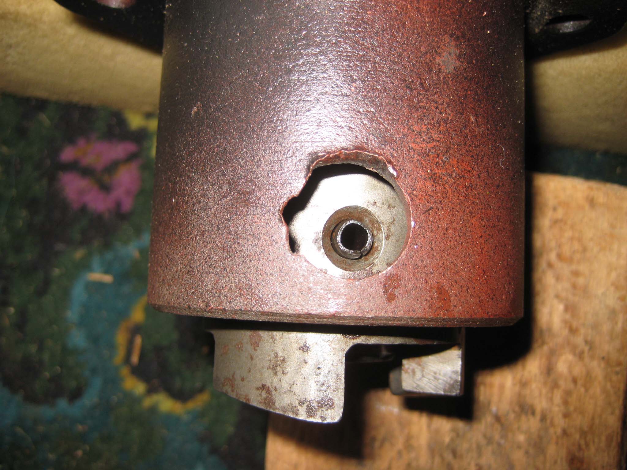
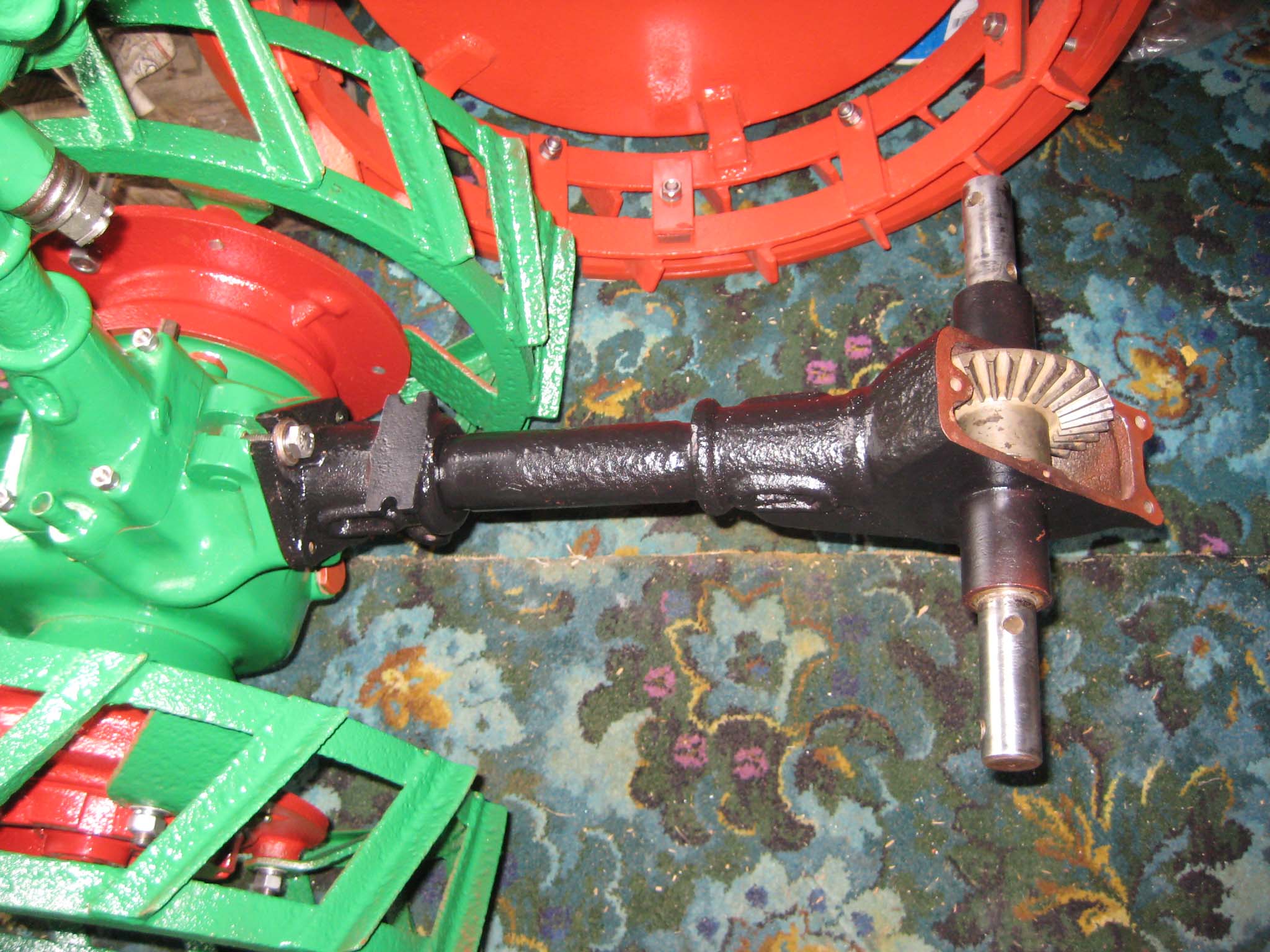
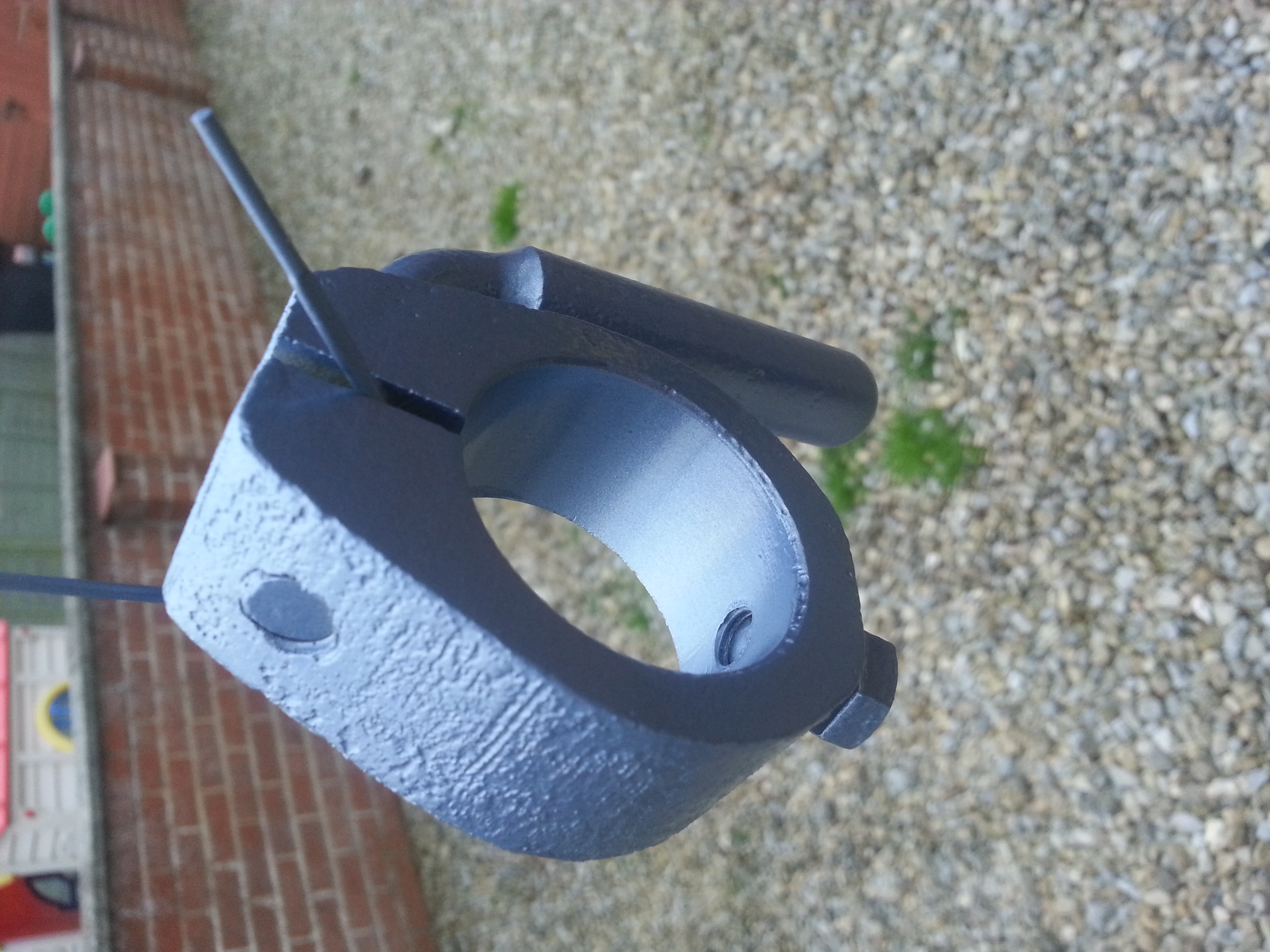
I next moved on to preparing the miller PTO assembly. The main drive shaft was fitted with a Steel thrust washer immediately behind the bevel pinion, followed by a Bronze thrust washer (Simar 0080). This was then fed through the Bronze bushes in the miller casing (Simar 0081). The crown wheel has thrust washers on either side. The left hand washer has cut outs in it to allow the keys on the miller cross shaft to pass through when the shaft is removed/installed. These are not visible when the unit is assembled, but there is a ‘V’ notch cut in the circumference of the washer which once lined up with a notch on the crown wheel indicates that the washer is correctly aligned for removal/installation of the cross shaft (Simar 0082). The right hand thrust washer includes a tab which sits in a notch on the inside of the miller casing, to ensure the washer does not spin against the casing wall (Simar 0083). Keys were fitted to the cross shaft (Simar 0084) and the shaft driven through the crown wheel from the left (Simar 0085). With the cross shaft in place, the left hand crown wheel thrust washer needs to be rotated by inserting a flat bladed screwdriver into the ‘V’ notch and gently tapping it around until the locking tab on the washer lines up with the notch in the crown wheel. Bend the tab over into the notch, so the washer will spin with the crown wheel (Simar 0086). The miller cross shaft bushes where then pressed into the casing. The bushes have a hole at one end which needs to align with a corresponding hole in the casing (Simar 0087 & 88). A pin will be installed later. The key was fitted to the driven end of the PTO shaft (Simar 0089) followed by the miller dog. The dog is held in place by a 6 x 50mm roll pin (Simar 0090). The miller PTO assembly was then bolted to the rear of the machine (Simar 0091).
Attachments:
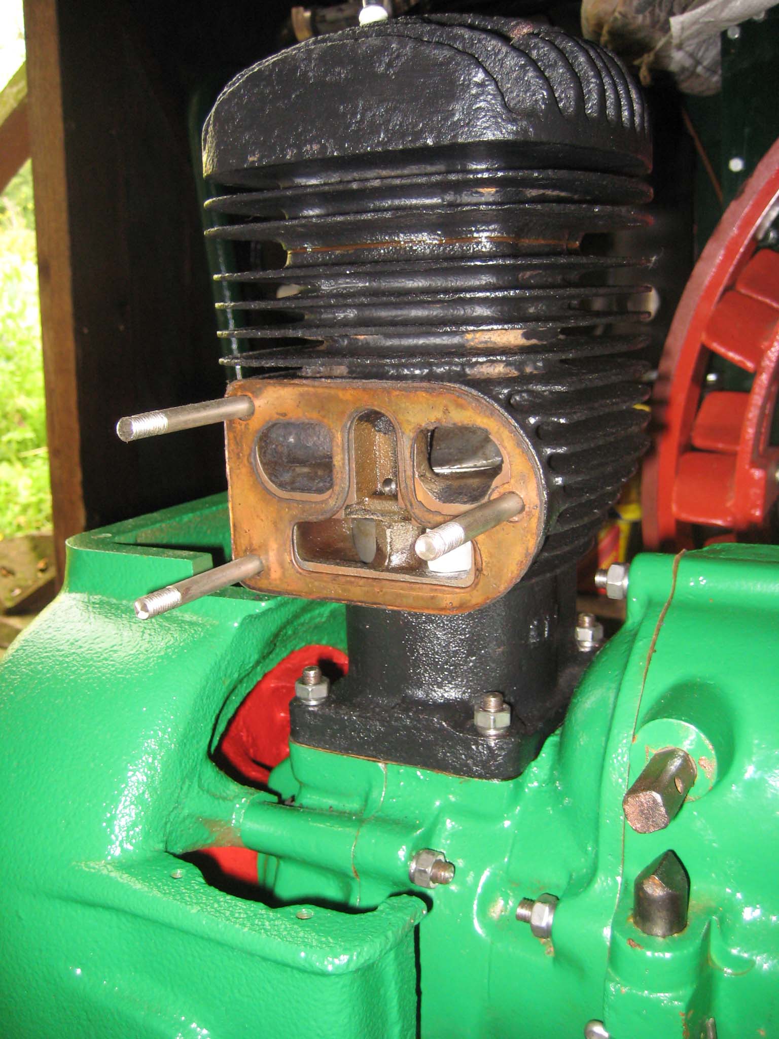
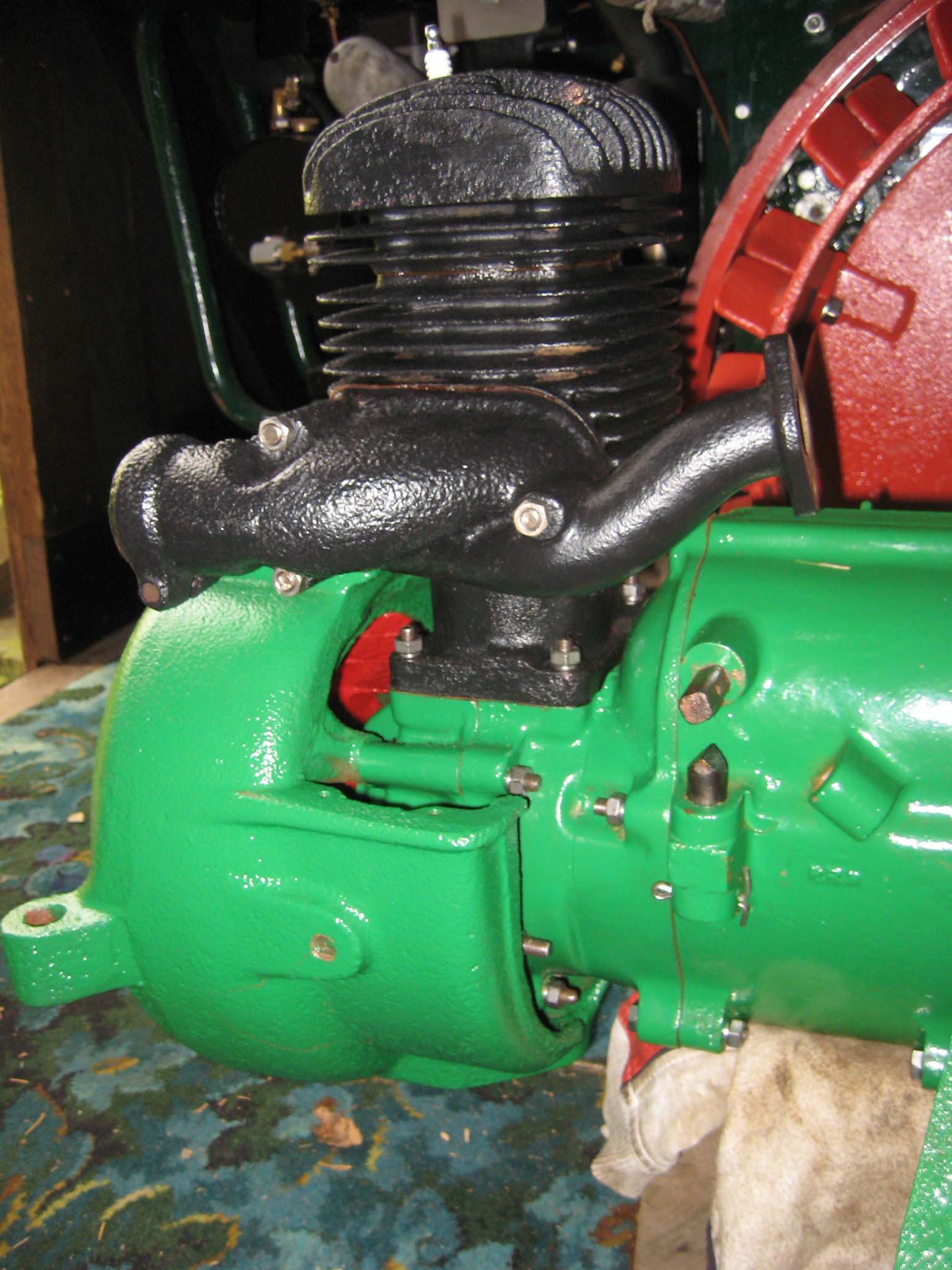
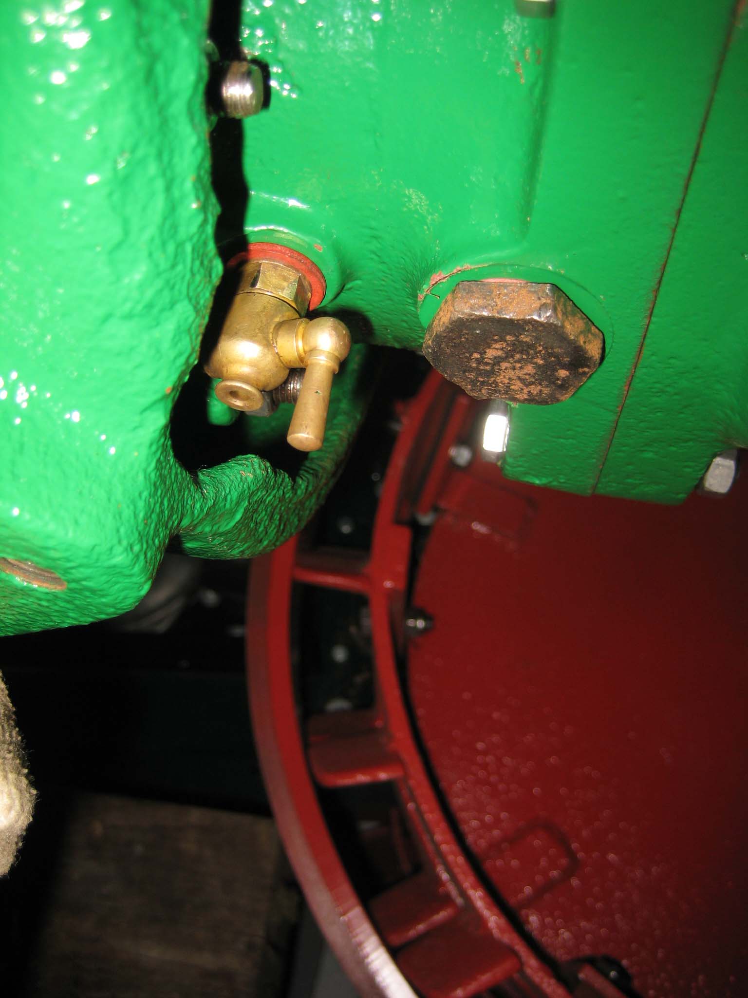
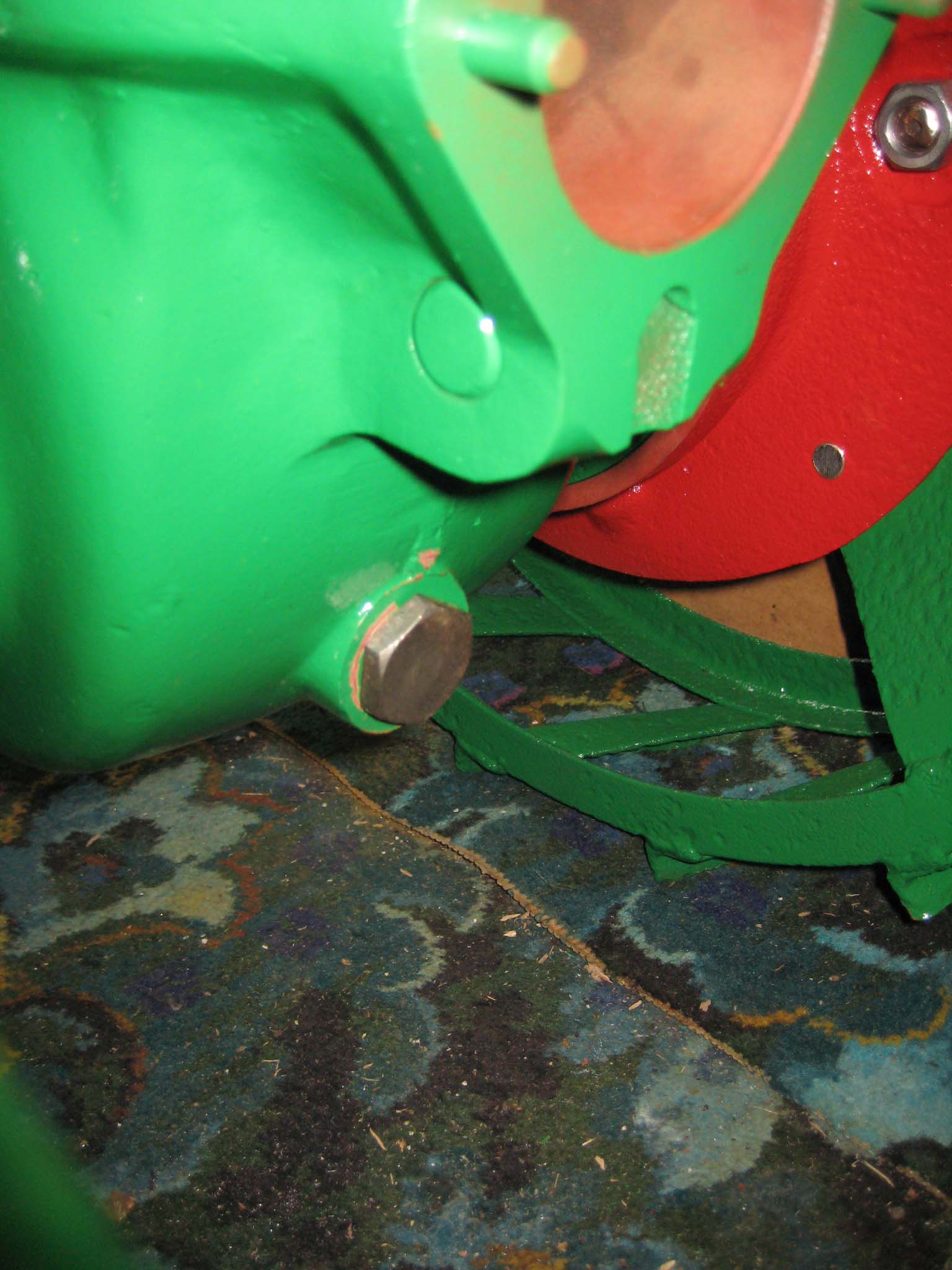
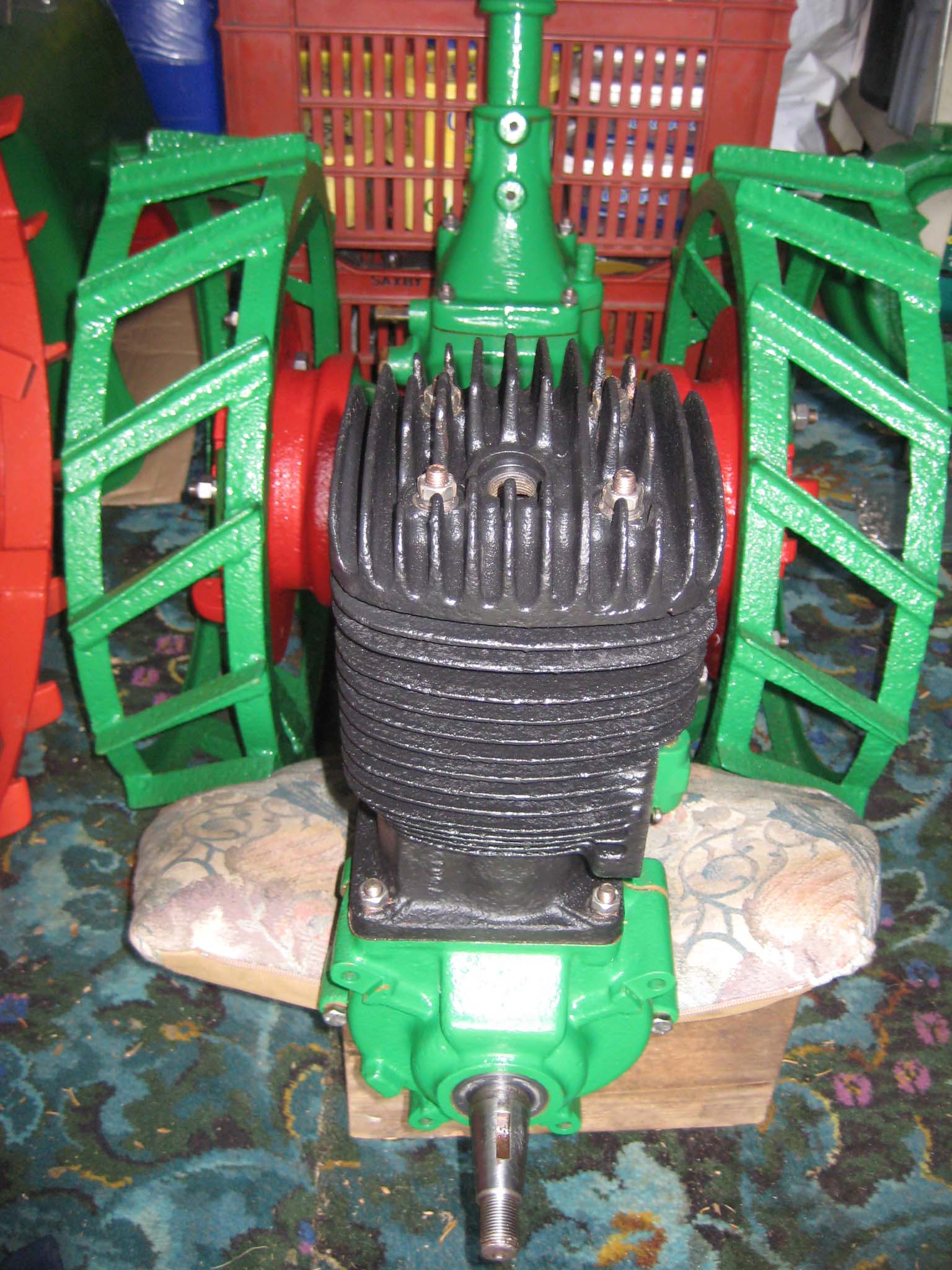
October 24, 2015 at 11:26 am #14937vhgmcbuddyMemberThree M8 studs were fitted into the cylinder barrel, along with the copper exhaust/air intake manifold gasket (Simar 0076), followed by the manifold (Simar 0077). The crankcase drain tap was re-fitted, along with the gearbox oil drain plug (Simar 0078). The tap would have been much easier to fit before the fan casing had been installed. There is another drain plug at the rear of the main gearbox (Simar 0079).
Attachments:
October 23, 2015 at 12:41 pm #14920vhgmcbuddyMemberHi Joe
Thanks for the information very much appreciated
Richard
October 22, 2015 at 6:17 pm #14907vhgmcbuddyMemberTractor looking great Alan !!
October 22, 2015 at 6:15 pm #14906vhgmcbuddyMemberJust emailed you short articles and photos on a couple of events for the December Cultivator Mr Editor sir !!
October 21, 2015 at 12:51 pm #14892vhgmcbuddyMemberTry again
Attachments:
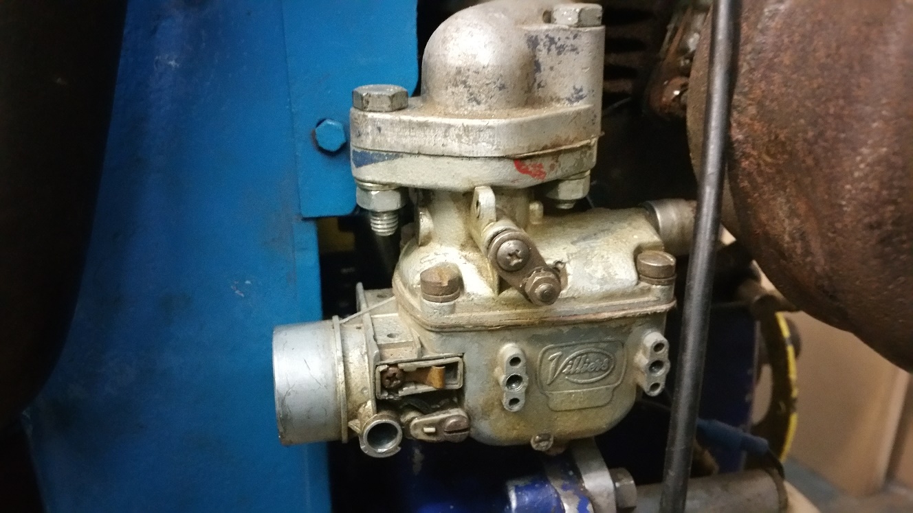
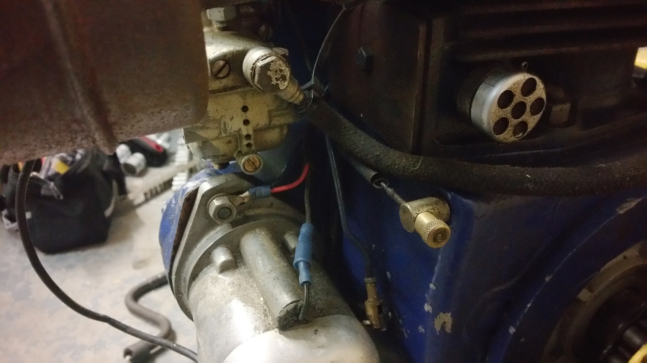
October 21, 2015 at 12:39 pm #14891vhgmcbuddyMemberHere are a couple of pics of the carb, I have checked the jets are clear on the carb but it looks like something is missing from the front of it.
So my question is can the missing bits be obtained or would it be easier to replace the carb?
October 19, 2015 at 4:32 pm #14882vhgmcbuddyMemberTry eBay, you can buy A4 size sheets.
October 18, 2015 at 4:28 pm #14869vhgmcbuddyMemberHi are you still looking for a tine cover
October 18, 2015 at 10:13 am #14866vhgmcbuddyMemberYeah i know! When i got it it had a seized 80s briggs & stratton on it. Dont know what happened to the origional unfortunately.
October 17, 2015 at 10:31 pm #14860vhgmcbuddyMemberHi
If you are still looking for e clips.
I needed a tiny e clip for carburettor from a motor triple. I ended up at Maplins and bought a selection box of about 300 various sizes for about £3.50.
The clip I needed was only about 1.6mm, but it was the easiest way to get one, bearing in mind the cost of postage etc.October 11, 2015 at 12:29 pm #14821vhgmcbuddyMembersmall update ive been waiting for some nice weather so i can get some blue on the main frame. at last its not been a bad day for it. still needs at least another 2 coats tho
Attachments:
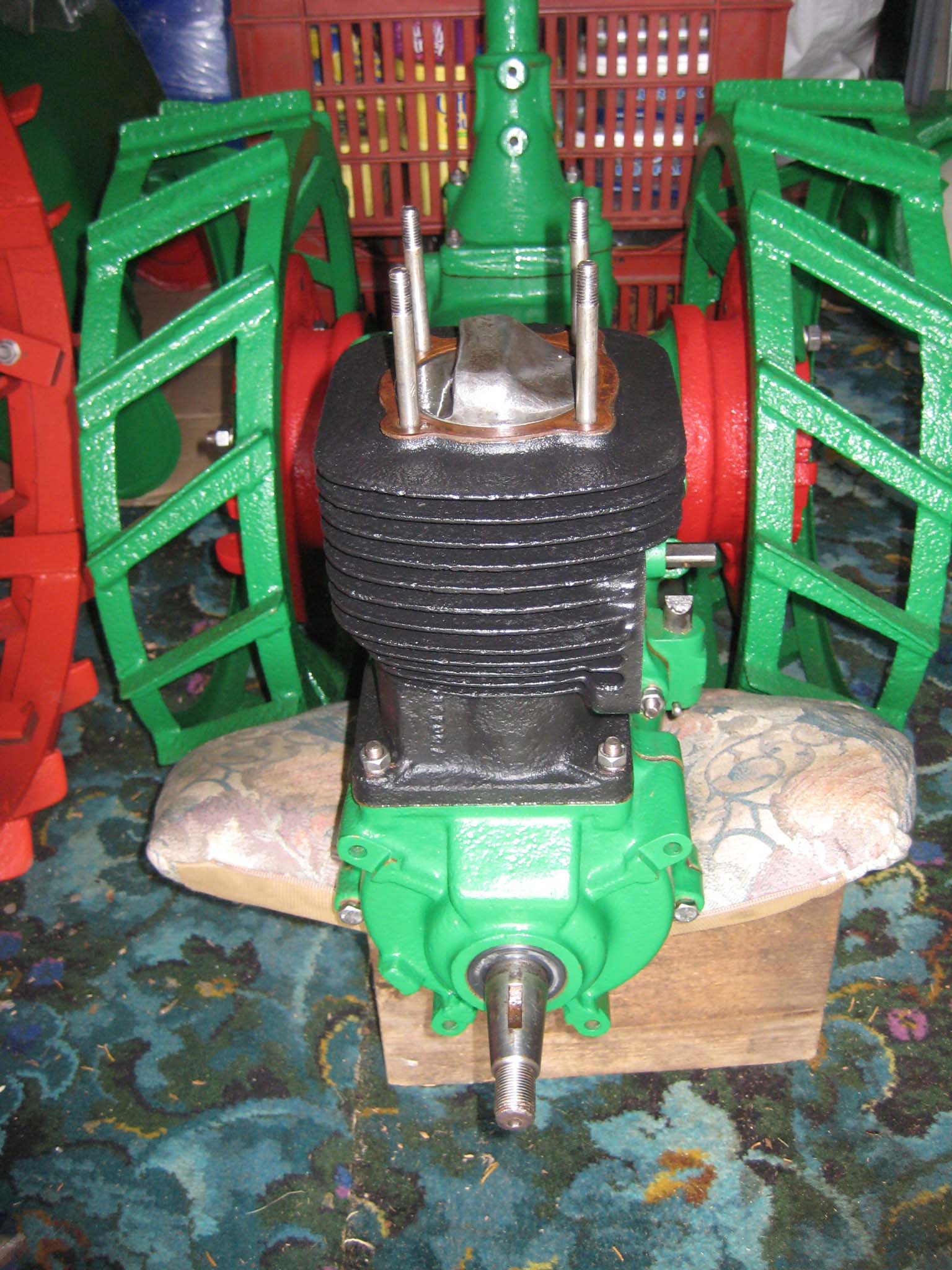
October 7, 2015 at 5:08 pm #14787vhgmcbuddyMemberAfter refitting the piston, the cylinder barrel, cylinder head studs and head gasket were installed (Simar 0071). Note the orientation of the piston. The cylinder head needs to be aligned so the spark plug hole is towards the front (Simar 0072).
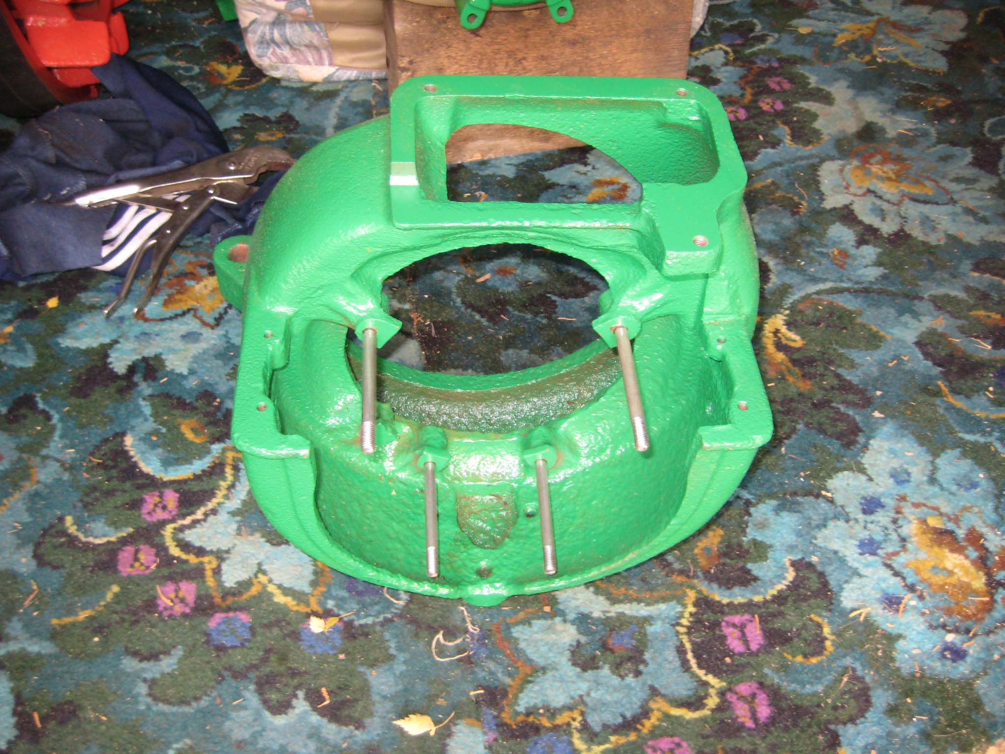
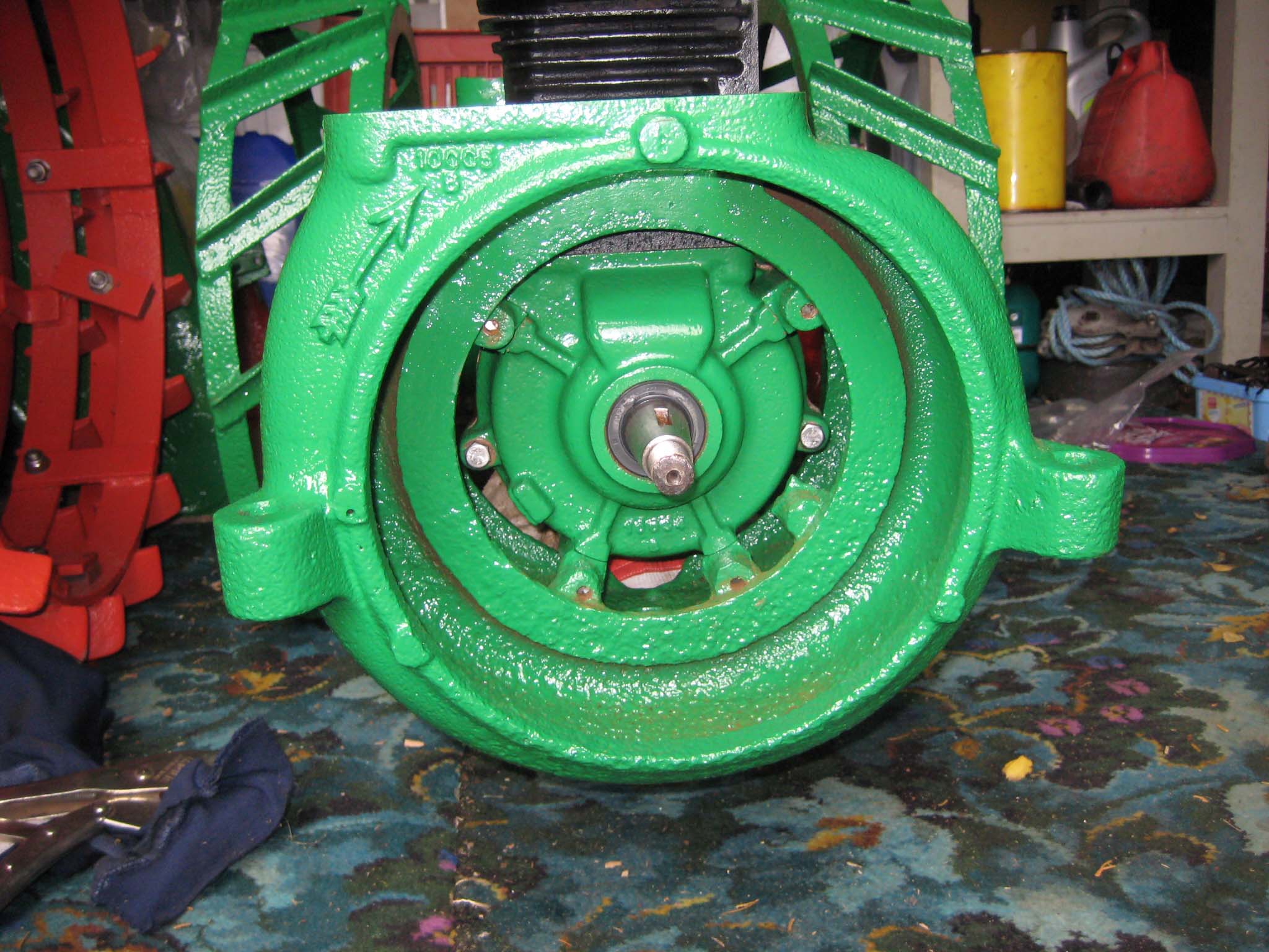
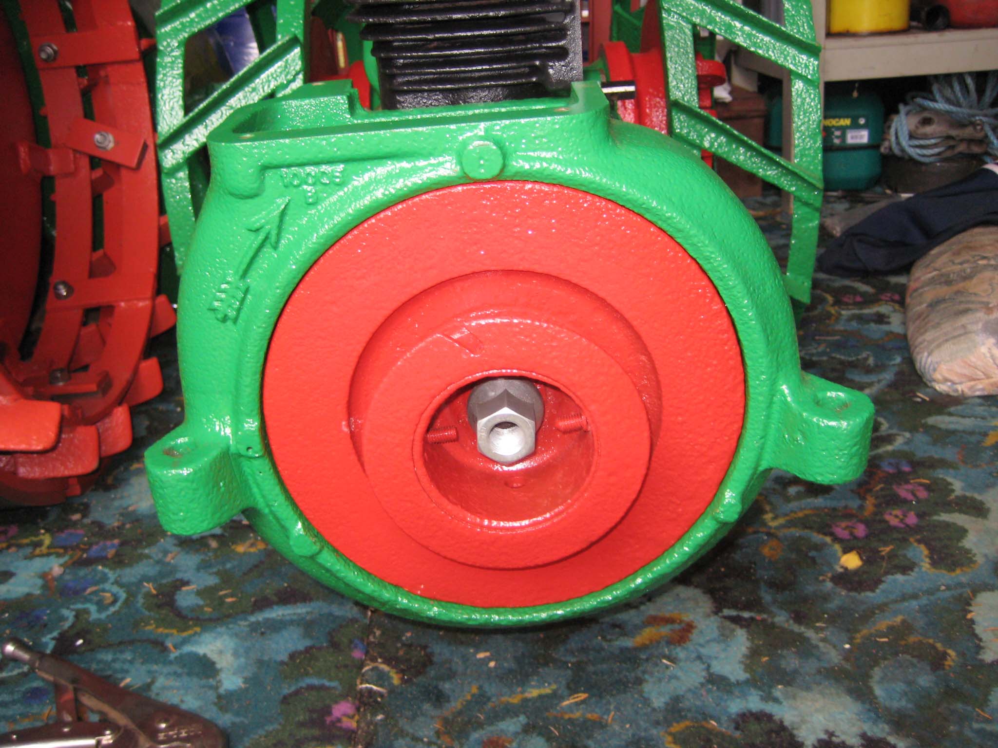
The cooling fan casing was prepared by installing the four M8 mounting studs (Simar 0073) and then fitted to the crankcase (Simar 0074). The cooling fan fits on the tapered crankshaft via a half moon key. A M18 x 1.5 nut holds the fan in place. The original nut was too corroded for reuse, so a replacement was obtained in the form of a wheel nut from a piece of agricultural machinery (Simar 0075). This also had the advantage of being a flanged nut, therefore I did not require the large washer which was used with the original nut. Note that in the photo the nut has yet to be tightened. The cylinder was filled with a cloth rag to lock the piston in place to allow the nut to be tightened.Attachments:
October 6, 2015 at 8:29 pm #14784vhgmcbuddyMemberMore blue bits just got main frame to sort next
Attachments:
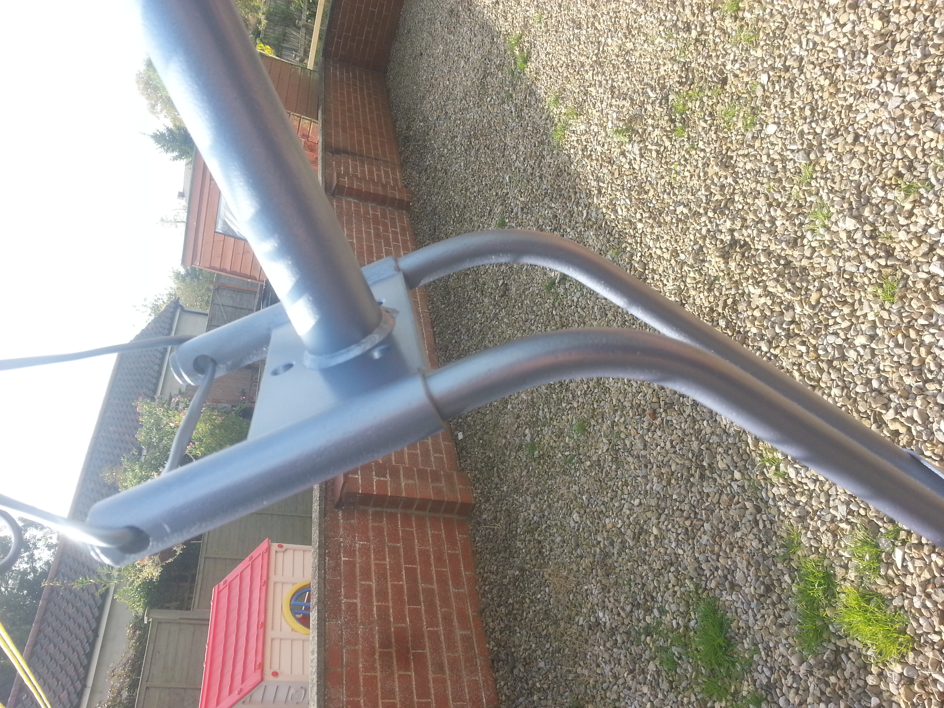
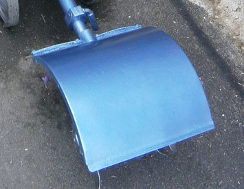
October 5, 2015 at 6:32 pm #14781vhgmcbuddyMemberRight people im needing some help im currently looking for one of these its a a metal cover for the rotovator head. As in the picture ? If anybody has one in reasnoable condition please contact me as ill happily buy it off you
Attachments:
-
AuthorPosts