Forum Replies Created
-
AuthorPosts
-
October 17, 2023 at 6:44 pm #41314
 vhgmcbuddyMember
Thanks Alan – much appreciated.
December 29, 2022 at 2:40 pm #40380vhgmcbuddyMember@vhgmcbuddy, I’m facing the same problem, not able to find the oil seals and they are already removed and damaged. Any tips on how you solved this issue with the rotary attachment?
June 26, 2022 at 3:18 pm #39301vhgmcbuddyMemberGreat thanks, yes going to take the clutch off for the time being.
Any sources of information or any manuals are much in need.
June 3, 2021 at 8:08 pm #37282vhgmcbuddyMemberThanks for your help, I knew I had seen it before, Just couldnt think where! I got it from my first car Boot sale this year last Sunday, I picked up a very nice copper faced hammer, and the chap offered me the ridger for £10.00 then £5.00 then £3.00 finally giving it to me for Free! Si it,s a bargain if ever I get a Monroetiller!
June 3, 2021 at 12:36 am #37277vhgmcbuddyMemberHeres Hoping this works
Attachments:
April 25, 2021 at 4:35 pm #37026vhgmcbuddyMemberHi,
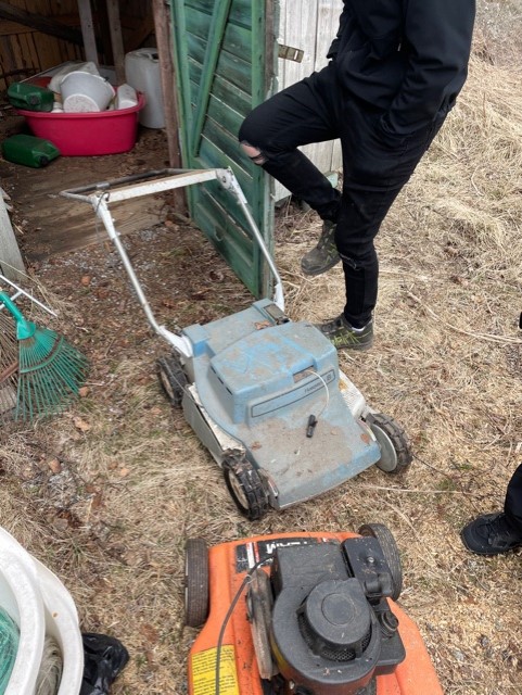
I have the blue Husqvarna Lawn mower from 1970 you are searching for, I think I just found one when I was looking in a house I just bought. It was in the back of many other things. You can buy it if you still are looking for one.
Attachments:
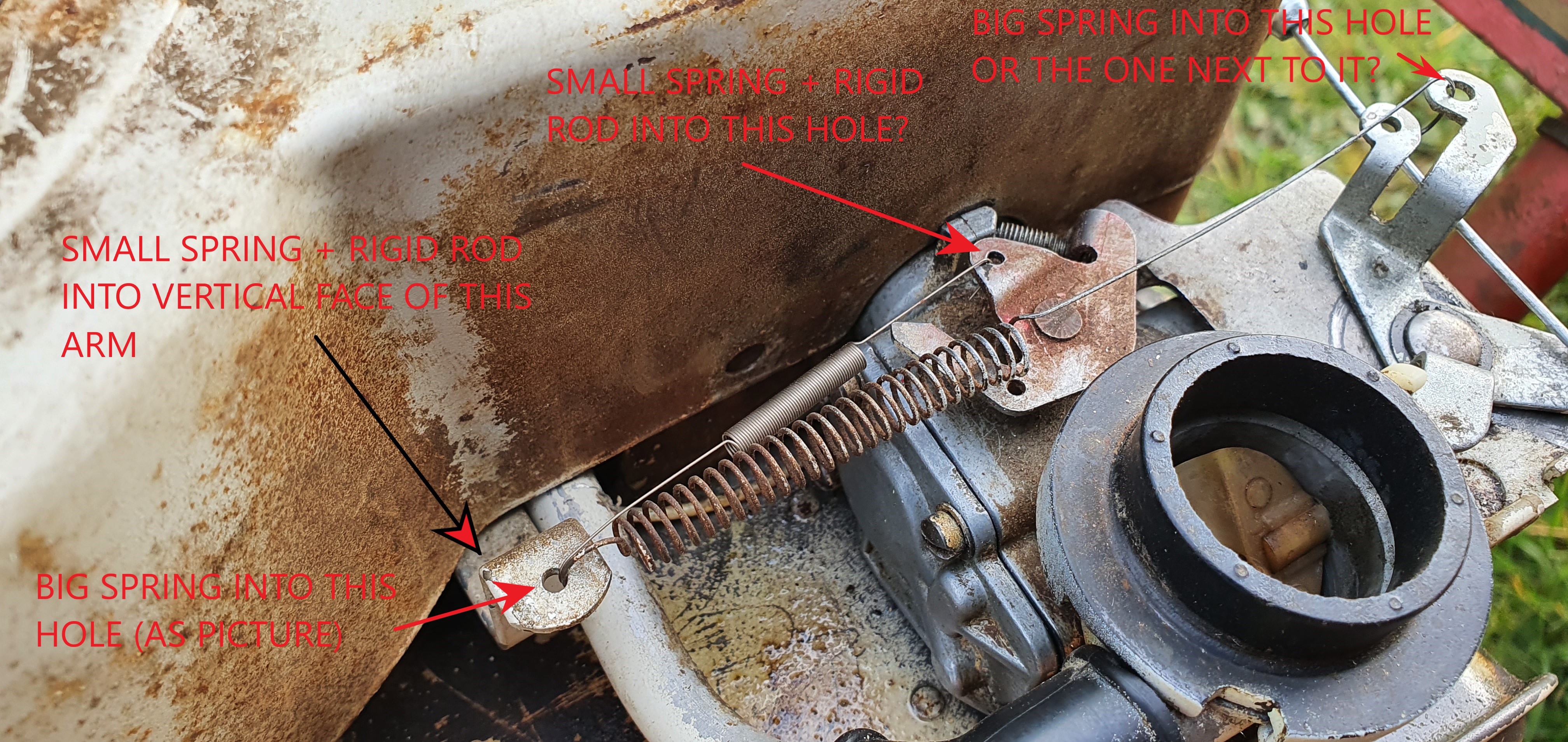
April 2, 2021 at 12:12 pm #36902vhgmcbuddyMemberAttached is an annotated picture of what I have interpreted from your description/picture. Would you agree on this?
A few questions beyond this….
The large spring goes into the piece that is also connected to the control cable. There are 2 possible connection points here for the spring. One where I have the spring currently and then another one closer to the carb. Have I got this in the correct hole or should I move that end of the spring to the other hole? I have got a new large spring by the way, but just used the old one for reference until I knew the correct orientation. I didn’t want to overstretch the spring until I knew where it should sit.
When I apply the rod and smaller spring, I think your images suggest the throttle spindle should be at its stop (with the control cable set at the “run” position). Where should the relative position of the rigid arm be? Set towards the carb or set away from it? This will of course define the length of the rigid rod that I have to make up. I dont want to make it too long.
Onwards from that, I guess it should run then and any other setup should be done by the carb jet screw. This may have been adjusted in this process so is there a good start point for the position of this? Screwed all the way in or 1 or 2 turns out?
Attachments:
April 2, 2021 at 11:51 am #36901vhgmcbuddyMemberOh wow. That is amazing! Thank you so much for the assistance here. That is making sense.
I have struggled to find the rigid rod, but have ordered a set from a different machine (Honda motor). They are longer, so I should be able to trim and reform them to the correct length. I really want to try and get it done this weekend so this should work, even for a temporary solution.
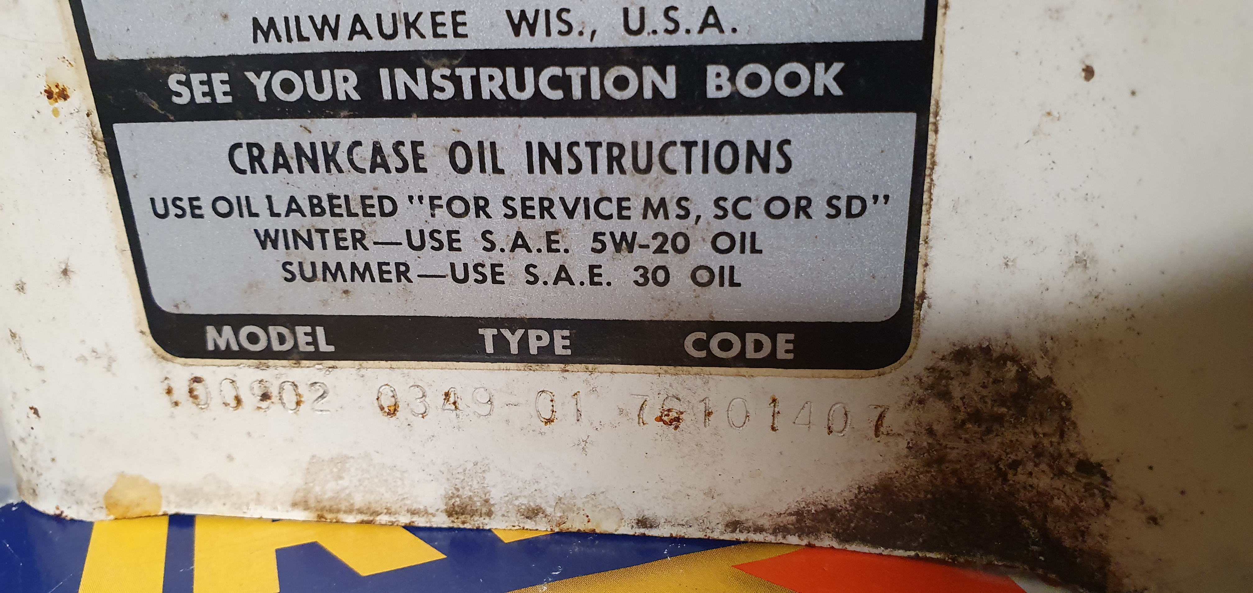
April 2, 2021 at 11:45 am #36900vhgmcbuddyMemberOk so the part number is…
100902 (Model) – 0349-01 (Type) – 76101407 (Code)
April 2, 2021 at 8:34 am #36891vhgmcbuddyMemberI did seem to recall a rigid link at some point. This may explain its seemingly wild running.
Attached is a picture of the engine code. Hopefully clear enough.
I’ve found a few exploded diagrams which shows a metal link rod, but I’m just not sure where it would go or if the current spring arrangement is correct!
Would love to see a picture of a properly setup one as a reference.
Attachments:
April 2, 2021 at 8:29 am #36890vhgmcbuddyMemberInitially it was a struggle to start, followed by the engine cutting out quite quickly. Last year it was occasionally tricky to start but then once it went it ran until it was put into STOP.
Having rebuilt the carb (cleaned, the new gaskets/diaphragm) and in its current configuration it now starts but seems to be revving really high. Sounds like it’s about to take off!
Guessing this is now a result of the missing/re-arranged components!
March 29, 2021 at 9:59 pm #36877vhgmcbuddyMemberOk so after hours of deliberation and talks with a mechanic friend along with some other research I have realised that the small fibre jockey wheel that seat back into the large gearbox pulley wheel is in fact a reverse option!
So the engine is driving it the right way, but I was only selecting reverse with the left handlebar cable…
If I bypass the smaller red wheel with the fibre disc and go from the engine pulley to the main wheel, the belt will rotate the large gearbox wheel the correctway and hence get forward motion!!!
So my next question is…. I assume there must be a drive belt that goes direct to the large gearbox wheel and should the large red gearbox wheel have another pulley for the belt to sit in? or does it also seat in the groove the reverse fibre disc drives in??
Any more help greatly appreciated… I’m sooo close
March 28, 2021 at 8:16 pm #36873vhgmcbuddyMemberDid the Wolseley Clearways ever have reverse?
March 28, 2021 at 7:50 pm #36872vhgmcbuddyMemberYes no unused pulleys at all… in this case I think I’ve been sold a complete lemon! It looks to me from other pics I found on line that the original engine pull start rotated the engine the other way. From what I gather, whoever put the new engine on also went to the lengths of fitting another cutting blade with the sharp edge on the opposite side. I think it was only until they started it and ran it they realised the mistake they had made!
I have only now realised it myself and have been ripped off by someone who said it cuts really well and has kept him going for years :0( I absolutely hate anybody who will lie to those lengths to mke a quick buck…
Maybe i can mod it as I am so far down the line now with restoring it
March 28, 2021 at 4:43 pm #36869vhgmcbuddyMemberI think the jockey pulley basically comes up and tightens the slack looking belt and forces it into drive
-
AuthorPosts