Home › Forums › The Machinery Forums › Pedestrian operated machines › Mountfield M1 – With Briggs & Stratton Engine
- This topic has 12 replies, 5 voices, and was last updated 5 years, 1 month ago by
coxey1979.
-
AuthorPosts
-
April 1, 2021 at 10:10 pm #36884
 vhgmcbuddyKeymaster
Hi,
New member here! I have an old Mountfield M1 (estate I believe). It has served me well for a couple of years, but having attempted to fire it up this spring it doesn’t seem to run correctly.
Regrettably I got someone to have a look at it who was unskilled and as a result some components seek to be lost! I have purchased several pieces and serviced the carb, also got it running slightly better however some of the carb pieces are definitely missing and I can’t for the life of me find a definitive image to understand what is missing and from where!
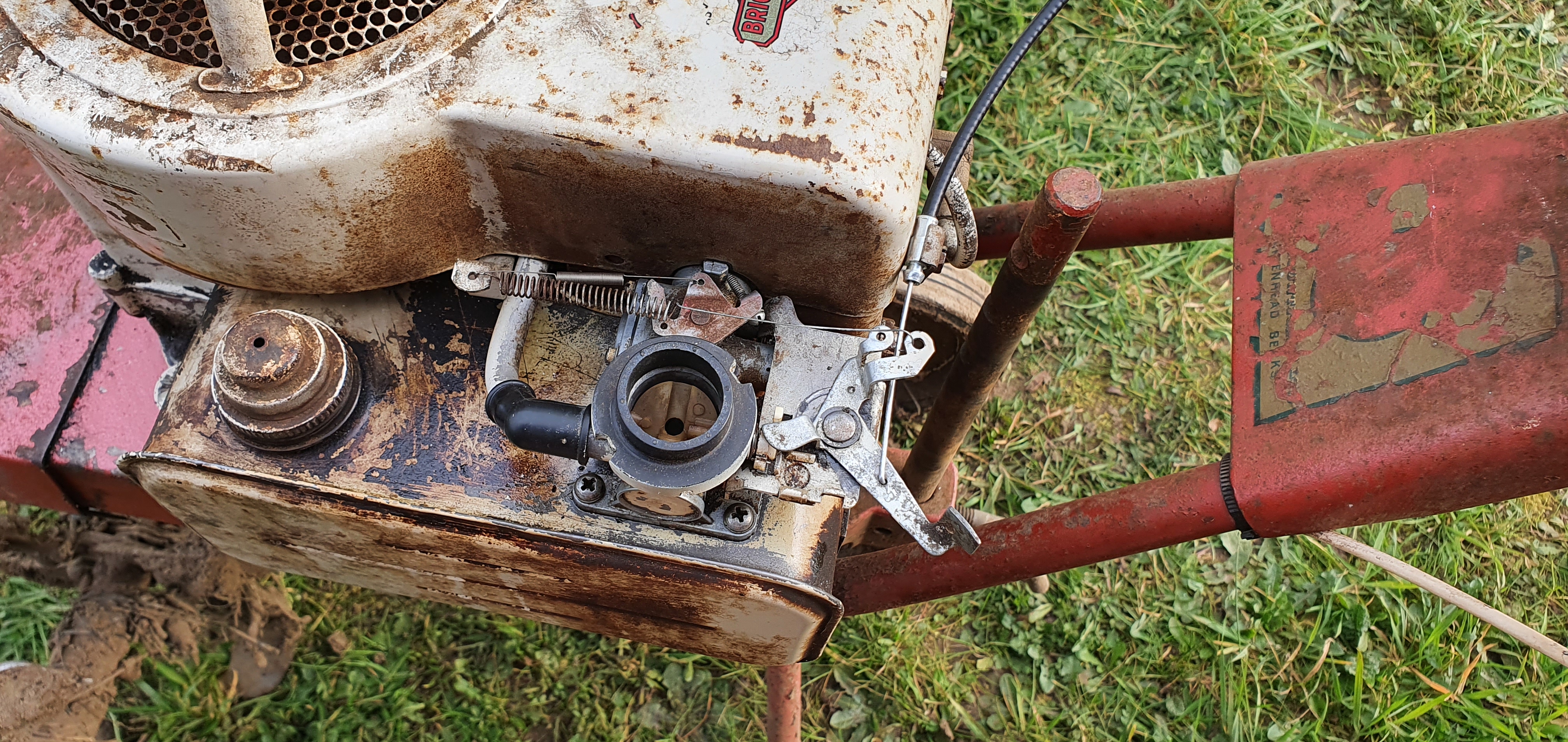
Attached are pictures of the carb in its current state.
Please help if you can!
Attachments:
April 1, 2021 at 10:23 pm #36887chris
ParticipantCarb looks complete to me, you do have the air filter that fits on top?
Have you reset the mixture screw on the carb?
What sort of poor running are you experiencing?April 2, 2021 at 7:21 am #36888 wristpinParticipant
Definite case of finger blight!
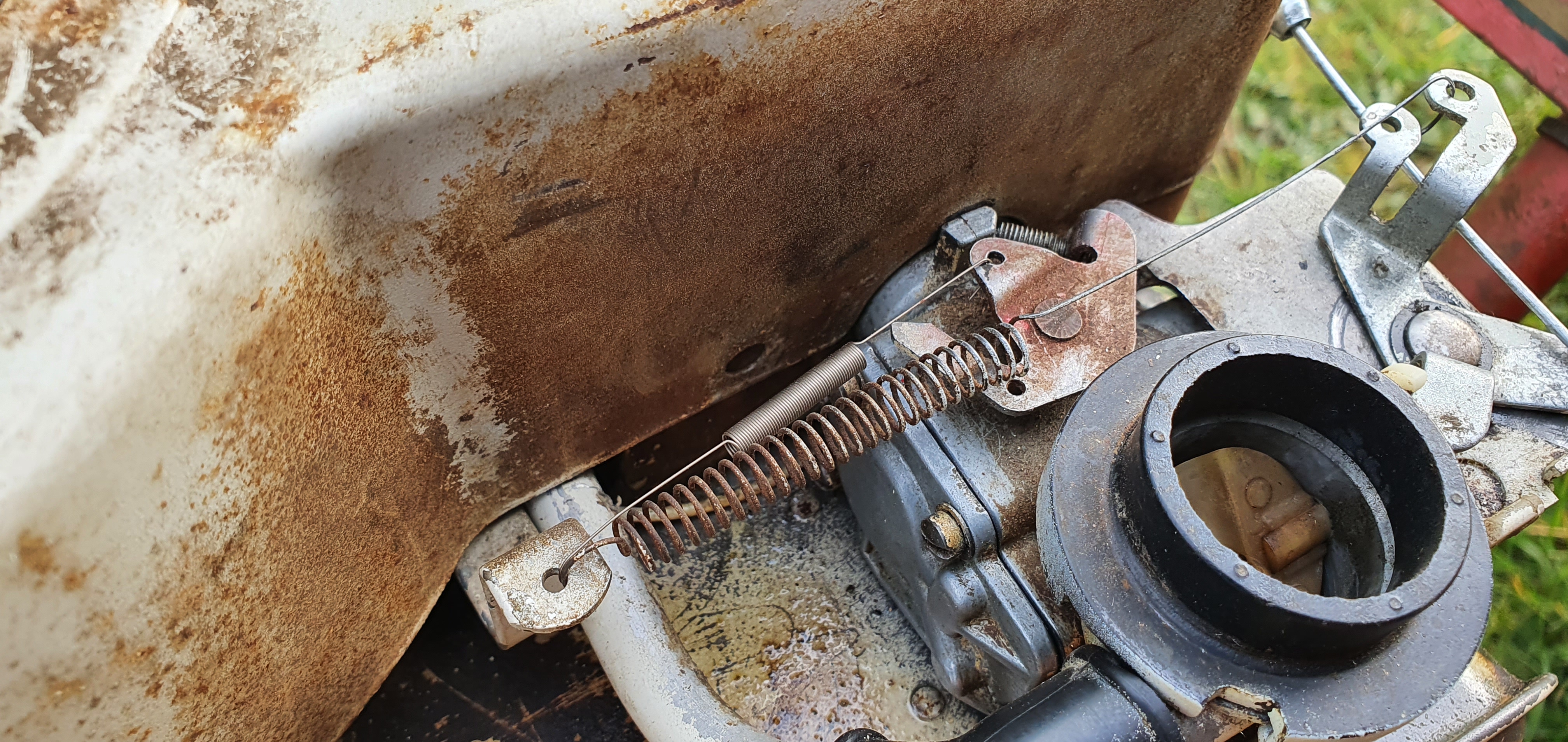
It appears to be missing a rigid link between the Governor arm and the throttle spindle but the perpetrator has repurposed the Governor spring to try to replace it. The small diameter spring threads over the missing link to keep the linkage in tension.
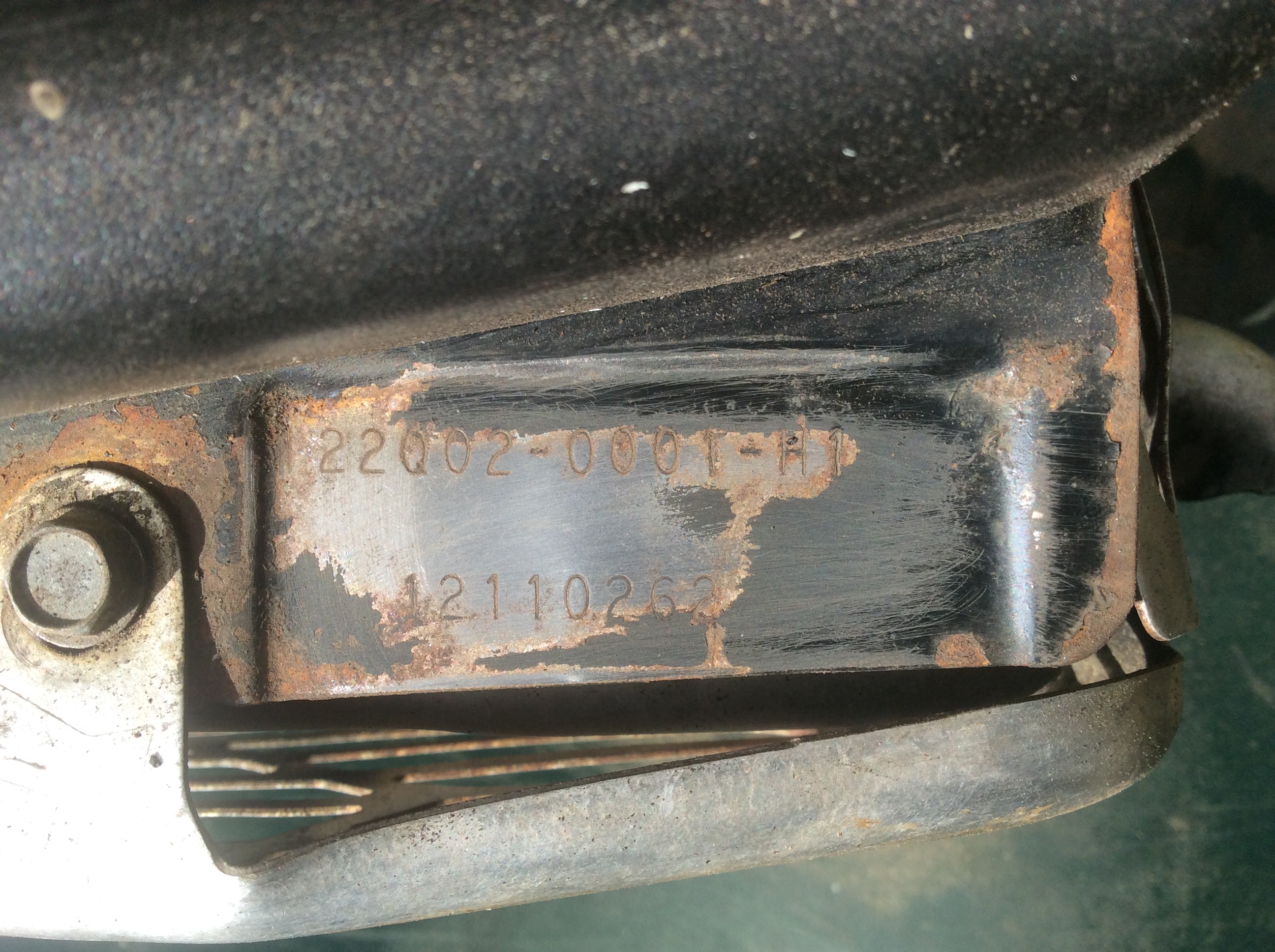
I’m struggling to find a decent schematic of how it should be, so please post the Model, Type and Code numbers that you will find stamped into the engine cowling – probably above the spark plug.
Meanwhile there’s another VHGMC member who to my knowledge has a similar cultivator and I will ping him a mail and he may be able to post an image of his machine.April 2, 2021 at 8:29 am #36890vhgmcbuddyKeymasterInitially it was a struggle to start, followed by the engine cutting out quite quickly. Last year it was occasionally tricky to start but then once it went it ran until it was put into STOP.
Having rebuilt the carb (cleaned, the new gaskets/diaphragm) and in its current configuration it now starts but seems to be revving really high. Sounds like it’s about to take off!
Guessing this is now a result of the missing/re-arranged components!
April 2, 2021 at 8:34 am #36891vhgmcbuddyKeymasterI did seem to recall a rigid link at some point. This may explain its seemingly wild running.
Attached is a picture of the engine code. Hopefully clear enough.
I’ve found a few exploded diagrams which shows a metal link rod, but I’m just not sure where it would go or if the current spring arrangement is correct!
Would love to see a picture of a properly setup one as a reference.
Attachments:
April 2, 2021 at 9:04 am #36894wristpinParticipantProblem, can’t read the MTC numbers in your post. You may need to lightly sand across them or high light them with a felt tip. Something like this. Or just post the numbers!
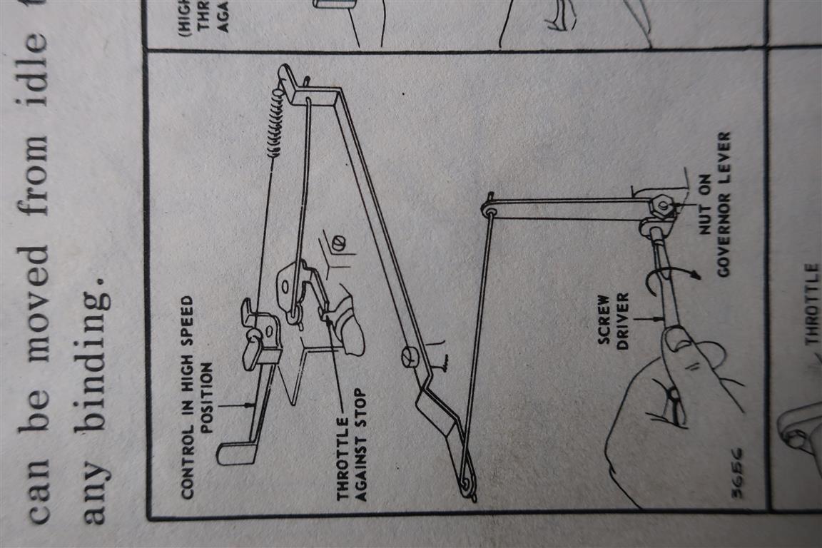
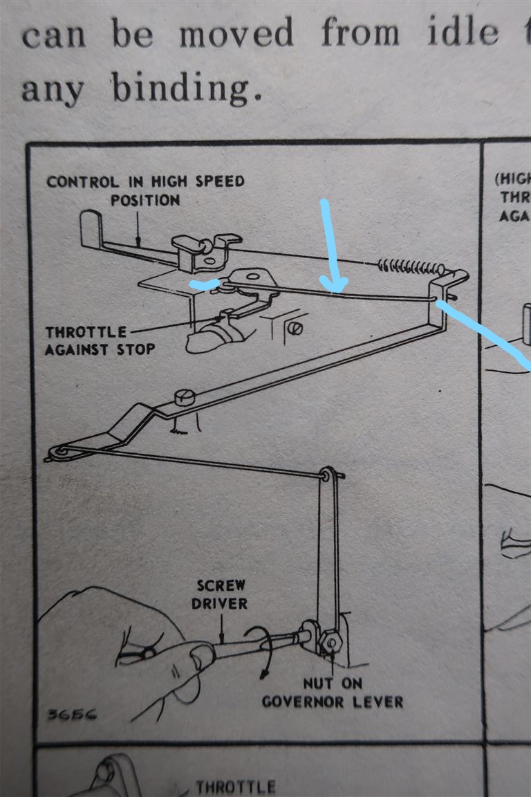
The rigid link will go between the horizontal arm that pokes out from under the flywheel and the plate on the top of the throttle spindle – that is the governor trying to shut the throttle The big (now overstretched) spring will be collected to the handle bar operated cable and the other end hooked to the governor / throttle spindle to oppose that closing force. What I can’t recall from memory is quite where that end should be located.
If anyone on this forum has a Hayter 21 with a 5hp Briggs, it probably has a similar set up.Attachments:
April 2, 2021 at 10:58 am #36896wristpinParticipantRight, finally got my brain into gear and found a diagram.
The big governor spring is in the correct place. Just round the corner from where it is hooked to the governor arm on the vertical bit , will be an empty hole. That’s where one end a short solid rod should go; the other end going to the throttle spindle. The thin spring probably slides up the short rod and shares its anchor holes at each end to keep the linkage taught but it will probably work ok without it. Those thin springs enclosing various rods are variously described as anti-rattle and anti-surge but are often missing or broken on older machines.
Ask your “mechanic” if he might happen to have a spare rod!
The rod is shown as still available, 260654 £4.55+vat or you could make one from a piece of piano wire. A bit of experimentation may be needed to get the length right but it shouldn’t be to difficult. The cranked ends need to be at right angles to one another.Attachments:
April 2, 2021 at 11:45 am #36900vhgmcbuddyKeymasterOk so the part number is…
100902 (Model) – 0349-01 (Type) – 76101407 (Code)
April 2, 2021 at 11:51 am #36901vhgmcbuddyKeymasterOh wow. That is amazing! Thank you so much for the assistance here. That is making sense.
I have struggled to find the rigid rod, but have ordered a set from a different machine (Honda motor). They are longer, so I should be able to trim and reform them to the correct length. I really want to try and get it done this weekend so this should work, even for a temporary solution.
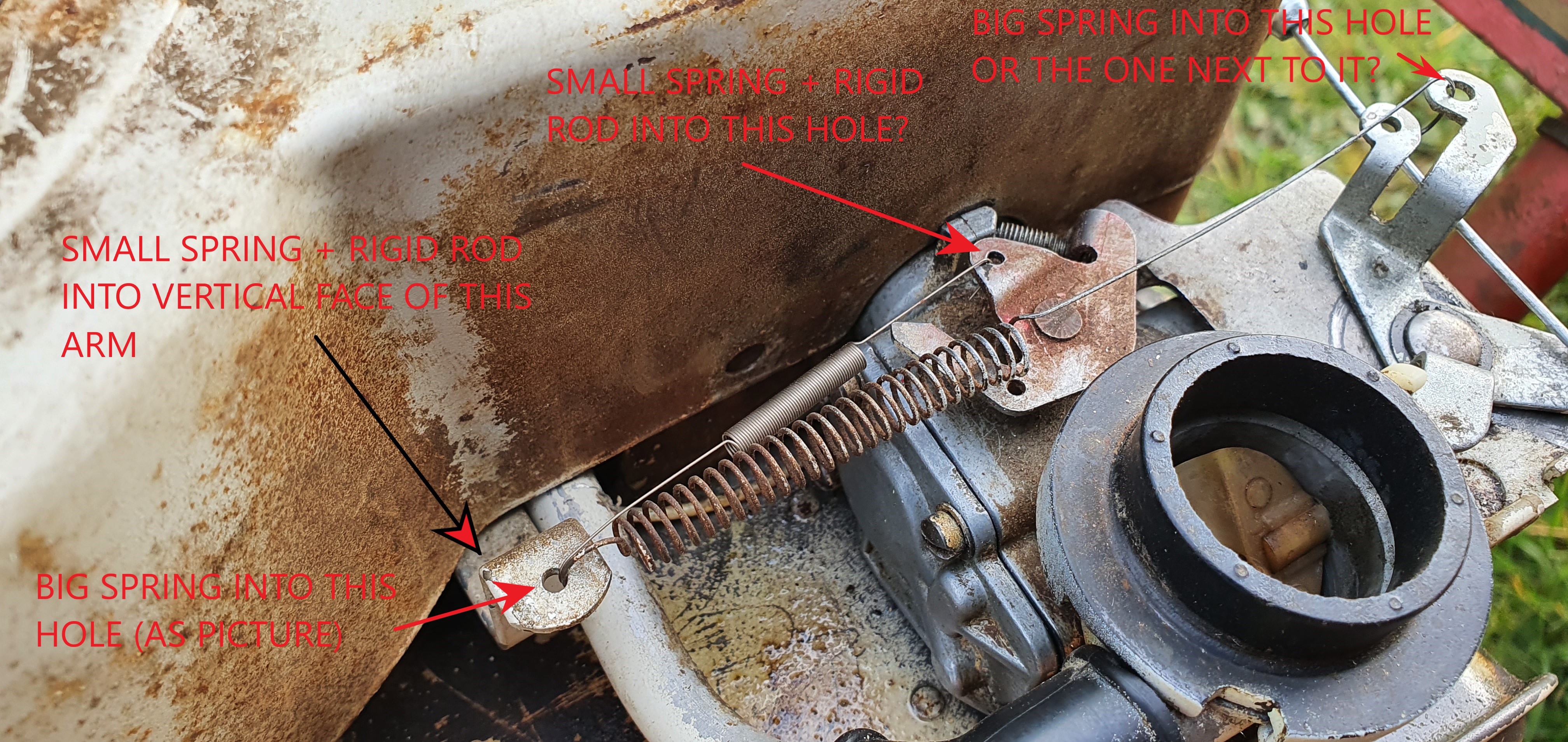
April 2, 2021 at 12:12 pm #36902vhgmcbuddyKeymasterAttached is an annotated picture of what I have interpreted from your description/picture. Would you agree on this?
A few questions beyond this….
The large spring goes into the piece that is also connected to the control cable. There are 2 possible connection points here for the spring. One where I have the spring currently and then another one closer to the carb. Have I got this in the correct hole or should I move that end of the spring to the other hole? I have got a new large spring by the way, but just used the old one for reference until I knew the correct orientation. I didn’t want to overstretch the spring until I knew where it should sit.
When I apply the rod and smaller spring, I think your images suggest the throttle spindle should be at its stop (with the control cable set at the “run” position). Where should the relative position of the rigid arm be? Set towards the carb or set away from it? This will of course define the length of the rigid rod that I have to make up. I dont want to make it too long.
Onwards from that, I guess it should run then and any other setup should be done by the carb jet screw. This may have been adjusted in this process so is there a good start point for the position of this? Screwed all the way in or 1 or 2 turns out?
Attachments:
April 2, 2021 at 1:28 pm #36904wristpinParticipantHopefully the other forum contributor will supply an image of his machine – a picture saves a thousand words etc.
The big spring is correct at the Governor arm end and at the cable end – I think.
The rod will be correct on the vertical face of the Governor arm. On the throttle plate are both the holes the same size, or is one showing a worn or more polished bore? My thoughts are that the correct hole is the one that’s not got the small spring in it at present.
If you are going to make a new link rod it’s a matter of taking the centre to centre measurement with both the variable elements in the same state ie with the Governor arm in the fully shut position and the throttle closed ( undo the idle stop screw until the throttle butterfly is fully closed) or with the governor arm wide open and the butterfly the same. For the sake of a fiver I’d get the correct rod as it will be the right length and save the hassle of forming the cracked end or ends with the first right right angle bends at exactly the right centres.April 2, 2021 at 2:39 pm #36905 hillsiderParticipant
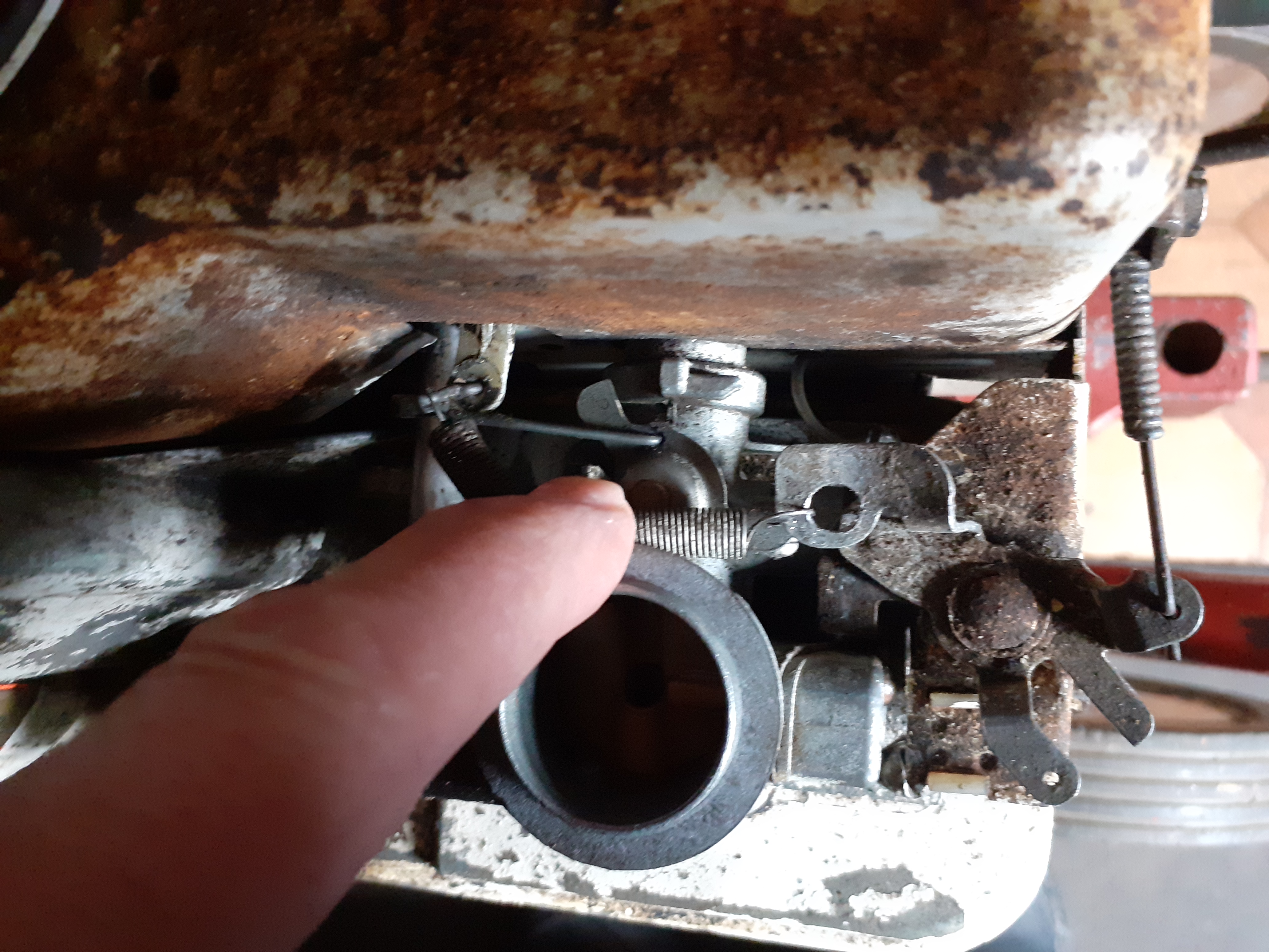
The engine fitted to my Mountfield M1 is the 3.5 hp 92908 series Briggs engine with an air vane type of governor but my photos will hopefully help to explain the link that wristpin is describing.
If your engine is larger capacity and has a mechanical governor this link could be longer in length than that on my engine but its function will be the same.Attachments:
June 19, 2021 at 10:42 am #37347coxey1979
ParticipantNot sure if it will help but here is a link to one of my posts and some photos of my carb, don’t know how else to share the link other than copy and past web address
I don’t have access to my machines for the foreseeable future (sperated and locked out my home) but I have digital manuals etc if you require.
Take care and stay safe, regards Mike
-
AuthorPosts

- You must be logged in to reply to this topic.