Forum Replies Created
-
AuthorPosts
-
November 13, 2015 at 1:47 pm #15174
 vhgmcbuddyMember
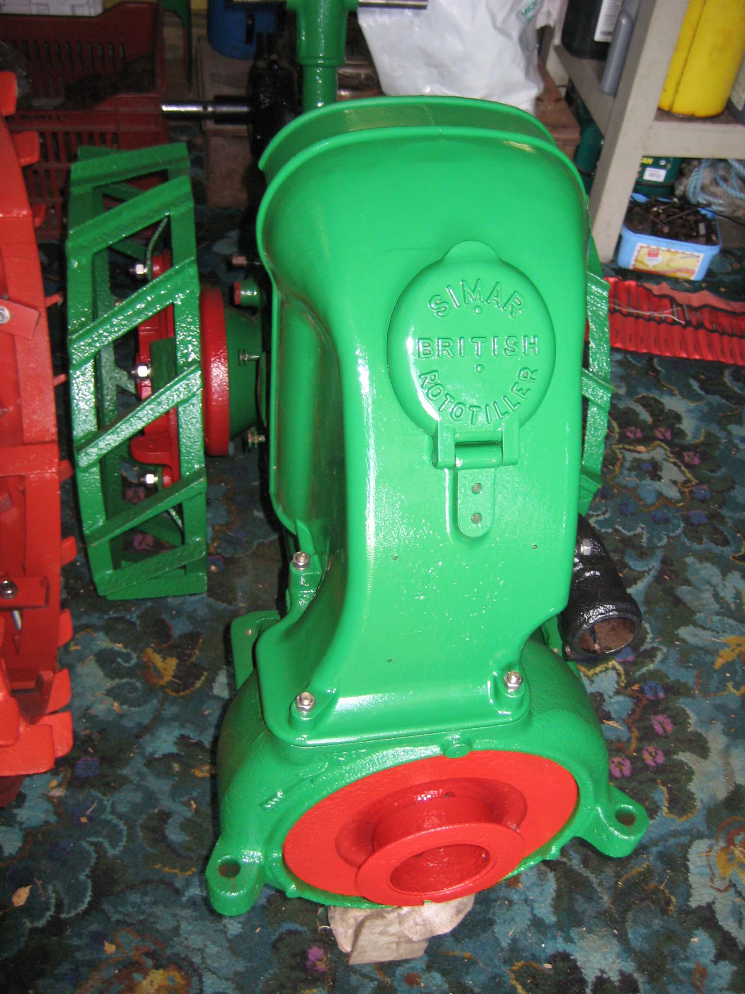
Hi Guys. Thankyou for the responses, I thought I’d post a few photos so you can get the gist of what I’m talking about.
The problem I’m getting isn’t the belt, everyone does belts Lol, it’s the tines (teeth) attached to the belt where I get stuck.
Royer industries was the one that wanted $600 for the privilege, which I thought was a bitter pill to swallow just for a belt.
I am trying the other contacts joegrgraham and you hortiman kindly gave me but I’m not holding out much hope.Attachments:
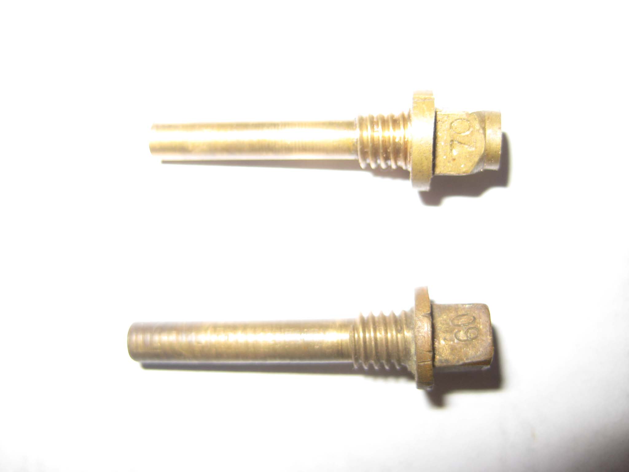
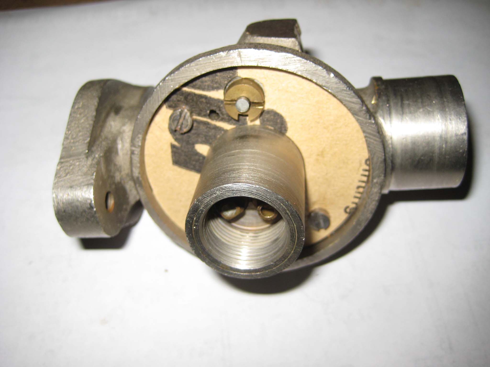
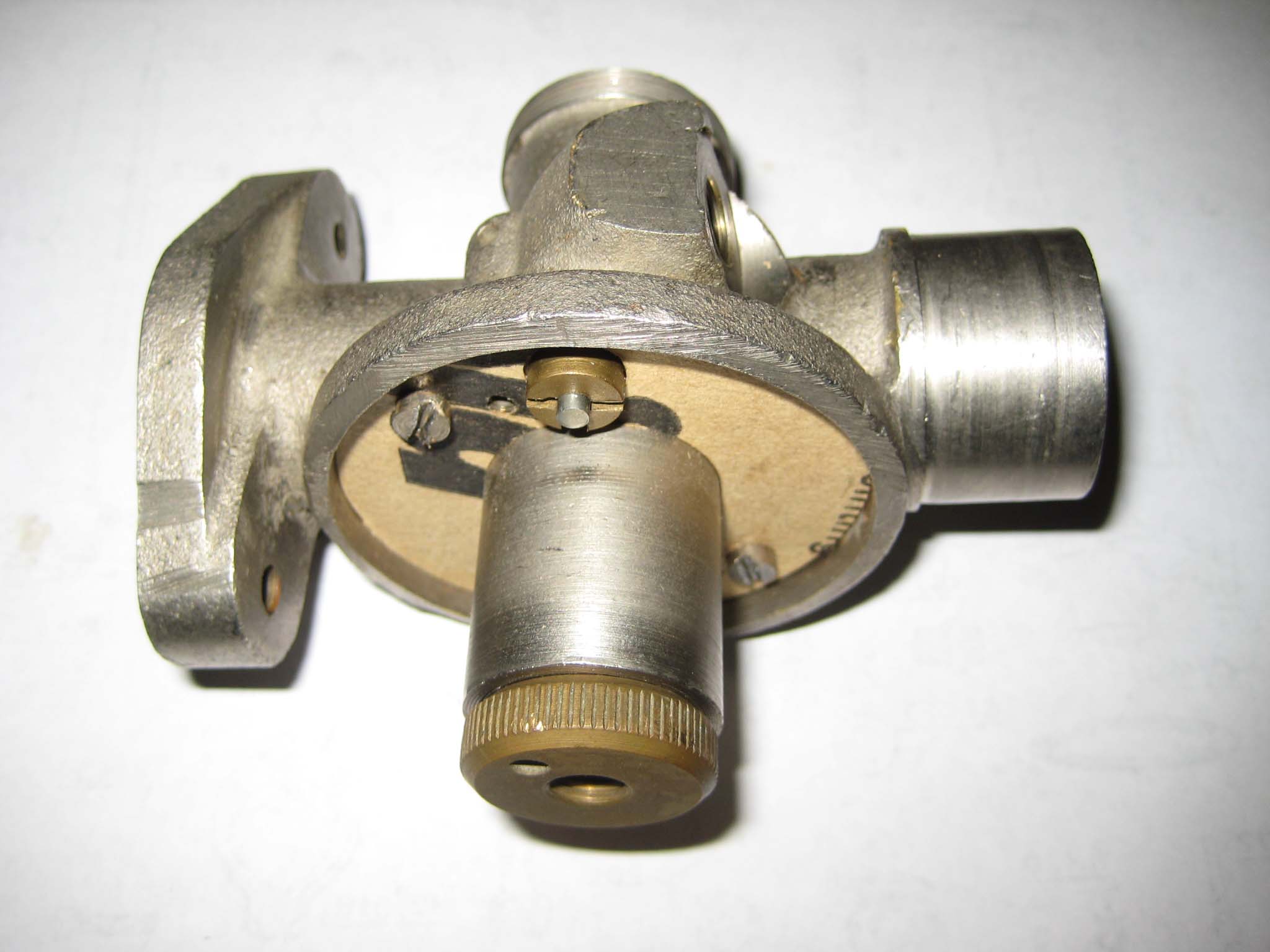
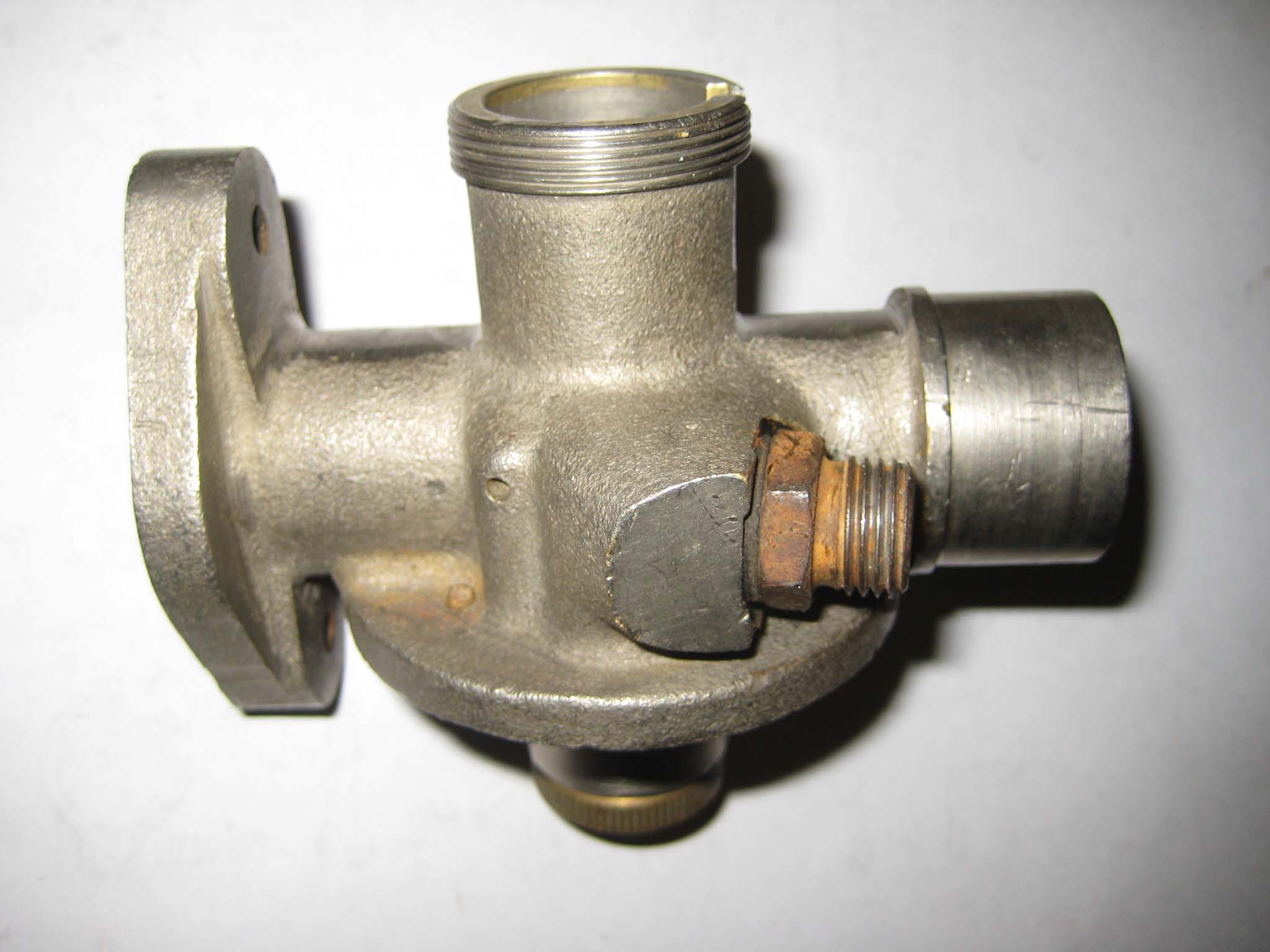
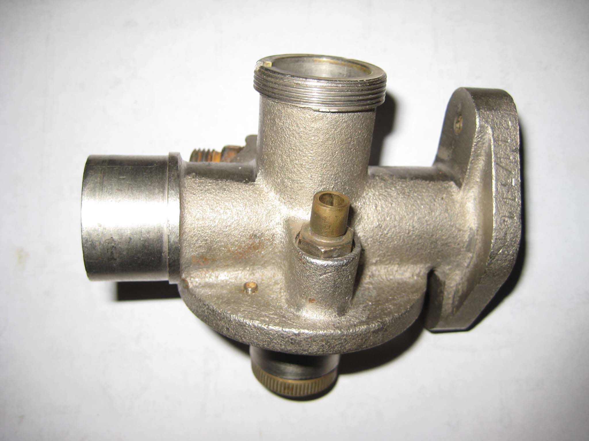
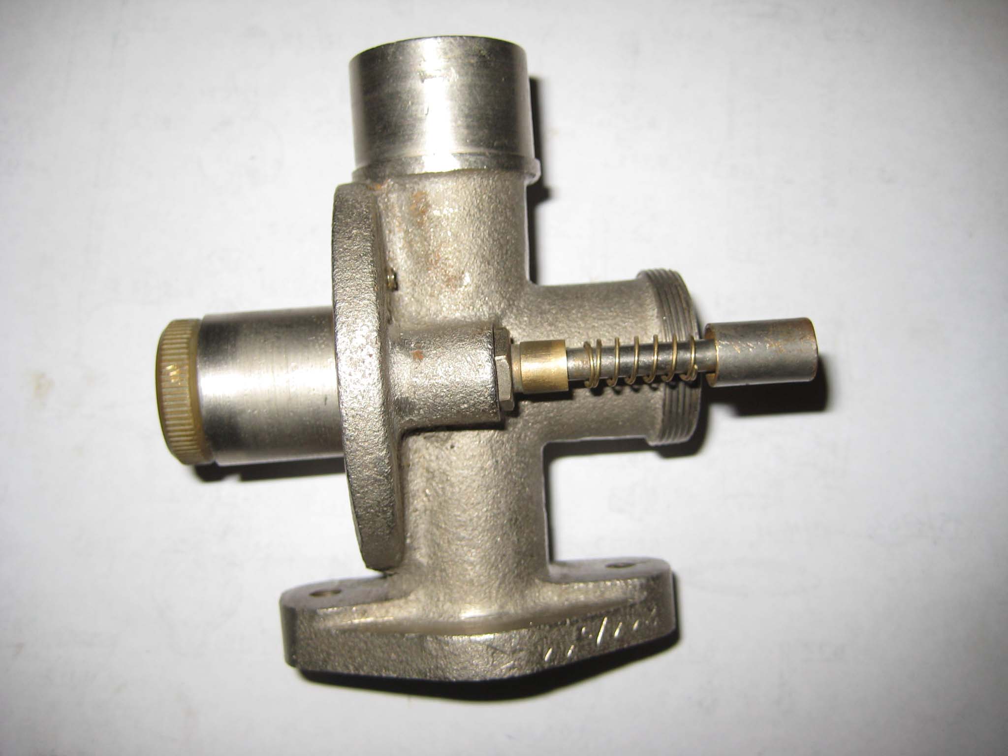
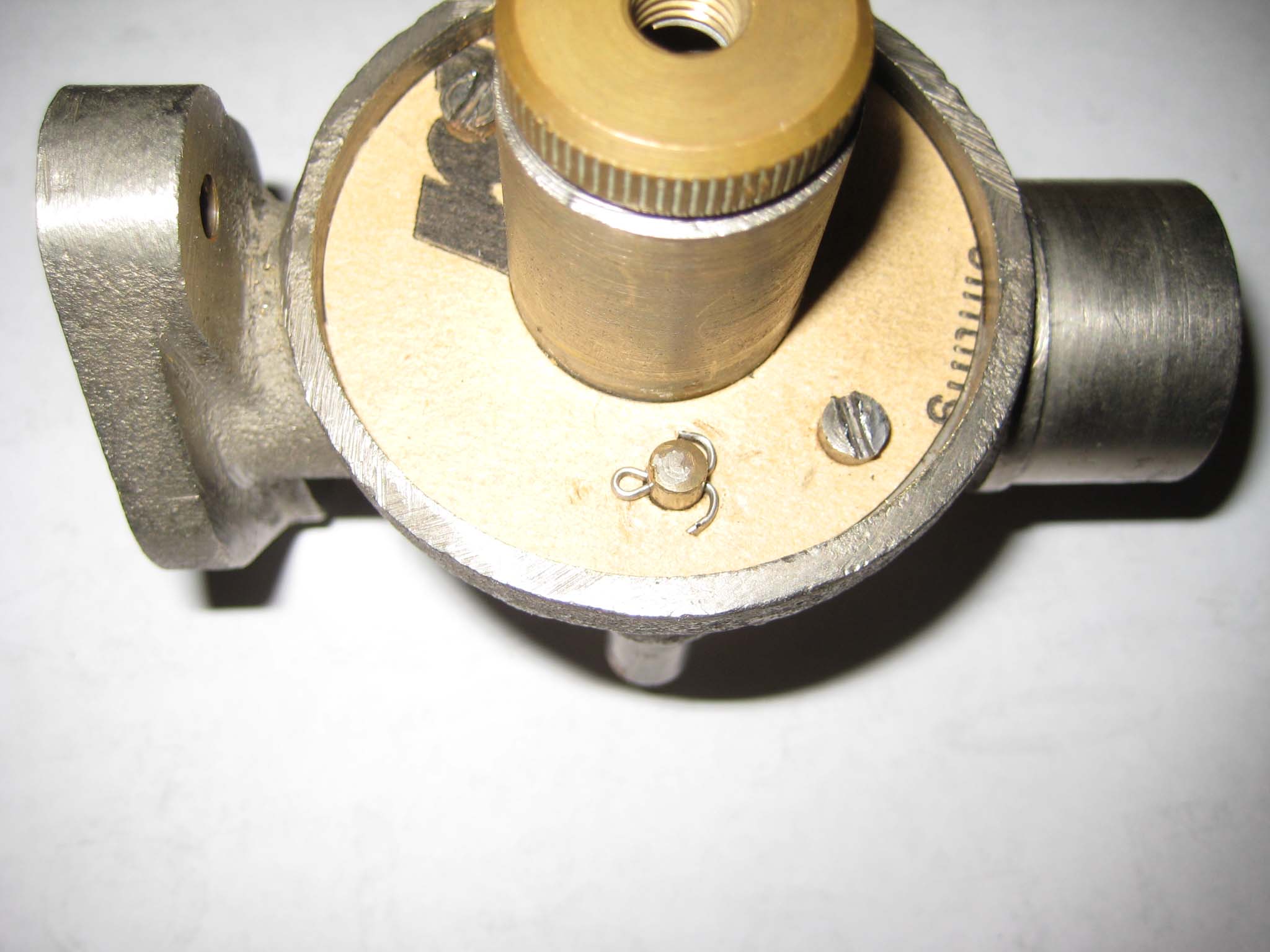
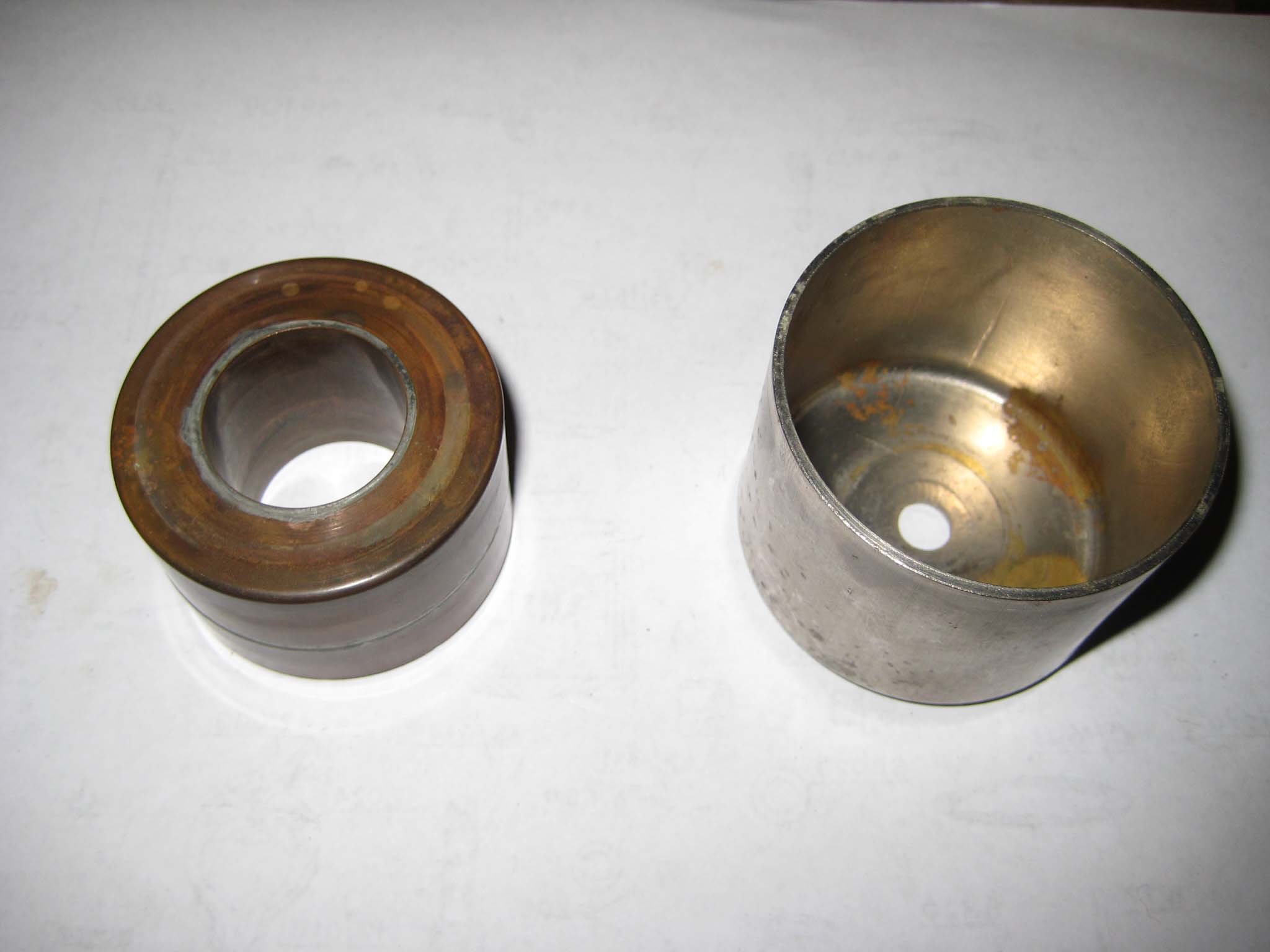
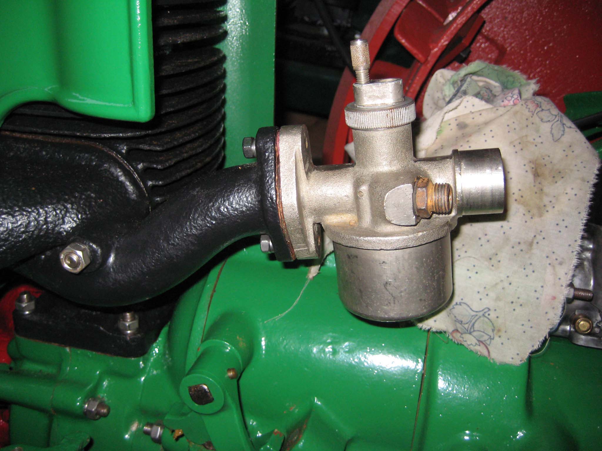
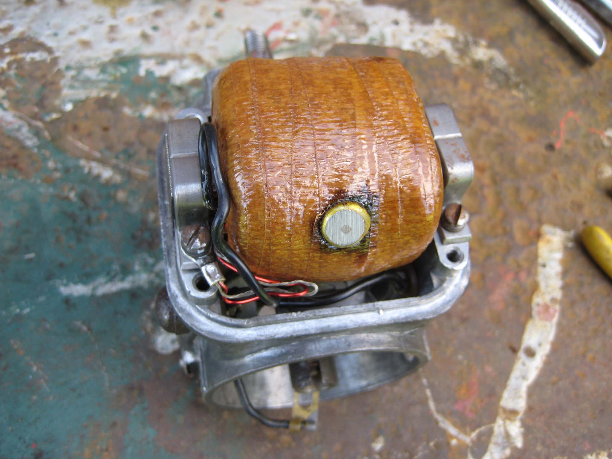
November 7, 2015 at 1:05 pm #15088vhgmcbuddyMemberI next focused my attention on the carburettor. At some point in the machines past, it had lost it’s original carburettor, having been fitted with an Amal 348/7. Charlie was able to provide me with the correct model number, this being an Amal 244/544. With this information, I was able to quickly track one down at a classic motorcycle spares seller in the north of England, although on dismantling this carb, I found that the main jet had been damaged by over tightening of the float bowl fixing bolt. So, the hunt was on for another, which after several months was found on that well known auction site. The item was indicated as being for a Simar 56, but using information posted on this forum, the size of the jets would suggest it was actually from a Simar 35, as the main jet was a size 60 instead of a size 70. This carb was also found to be missing it’s float, so I decided to use the first carb purchased.
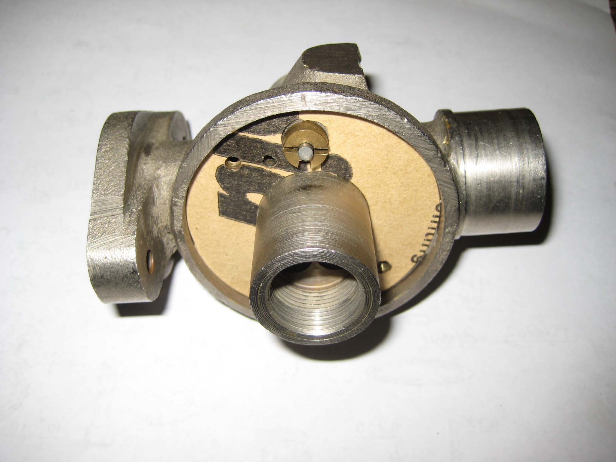
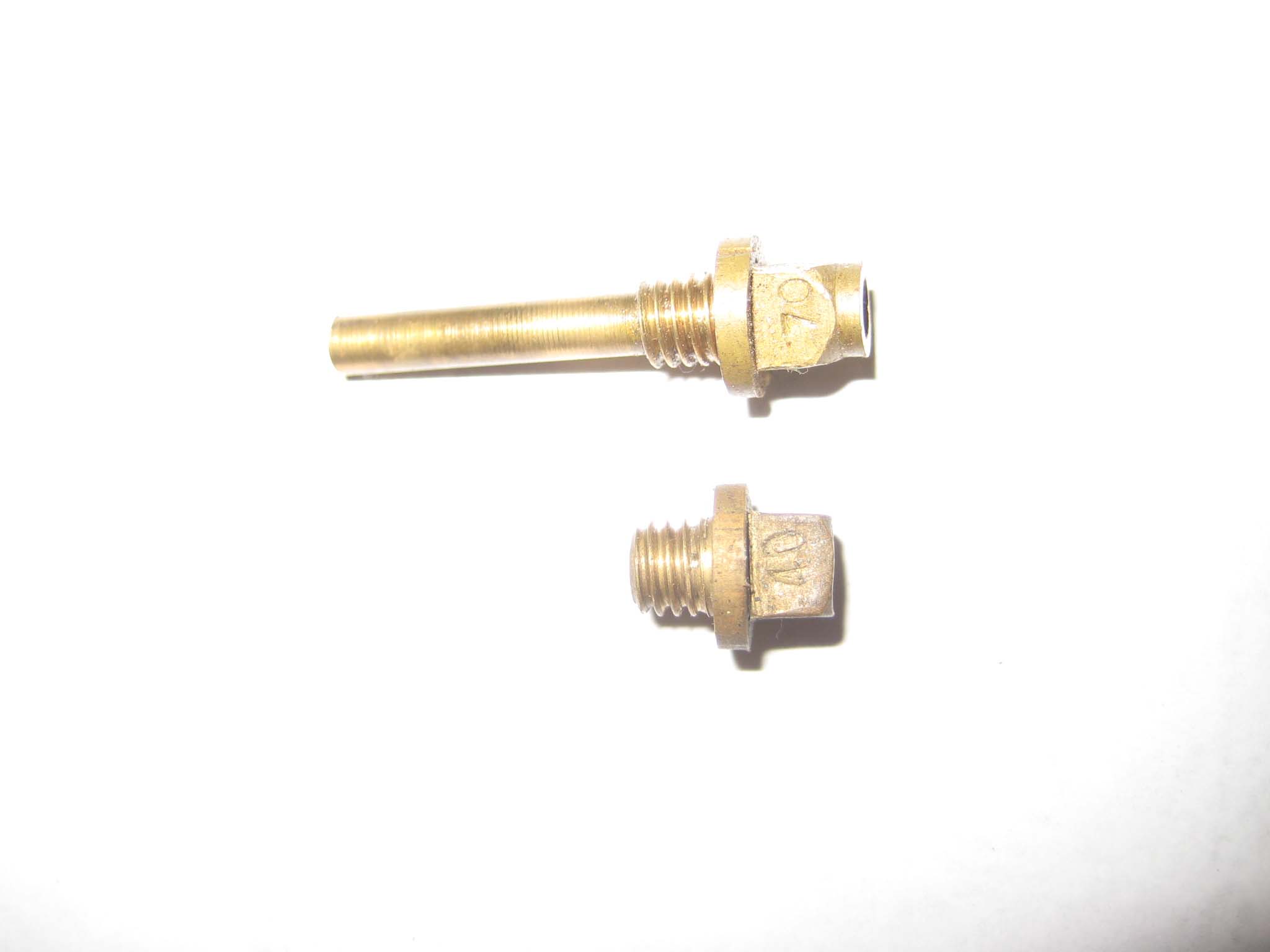
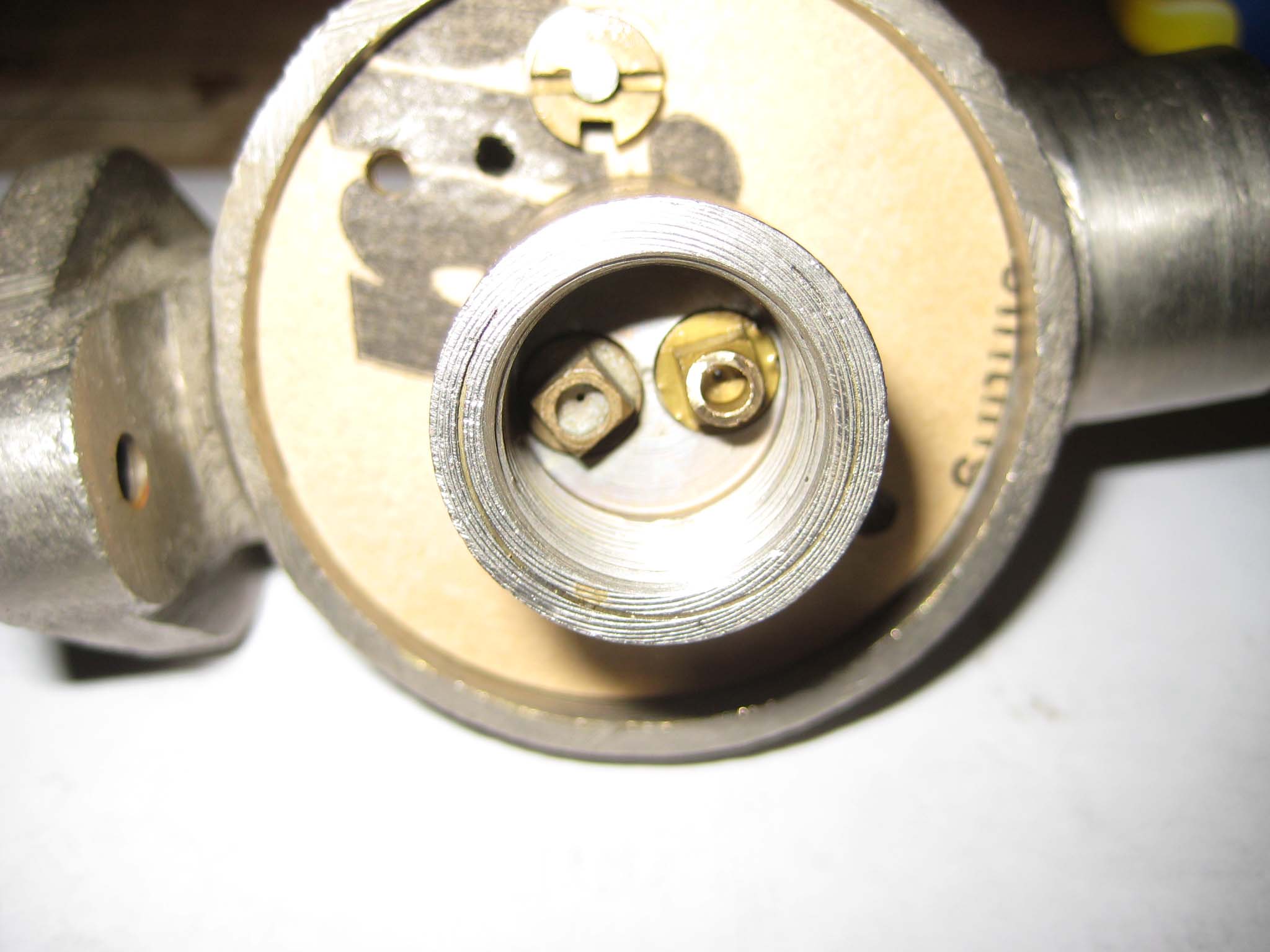
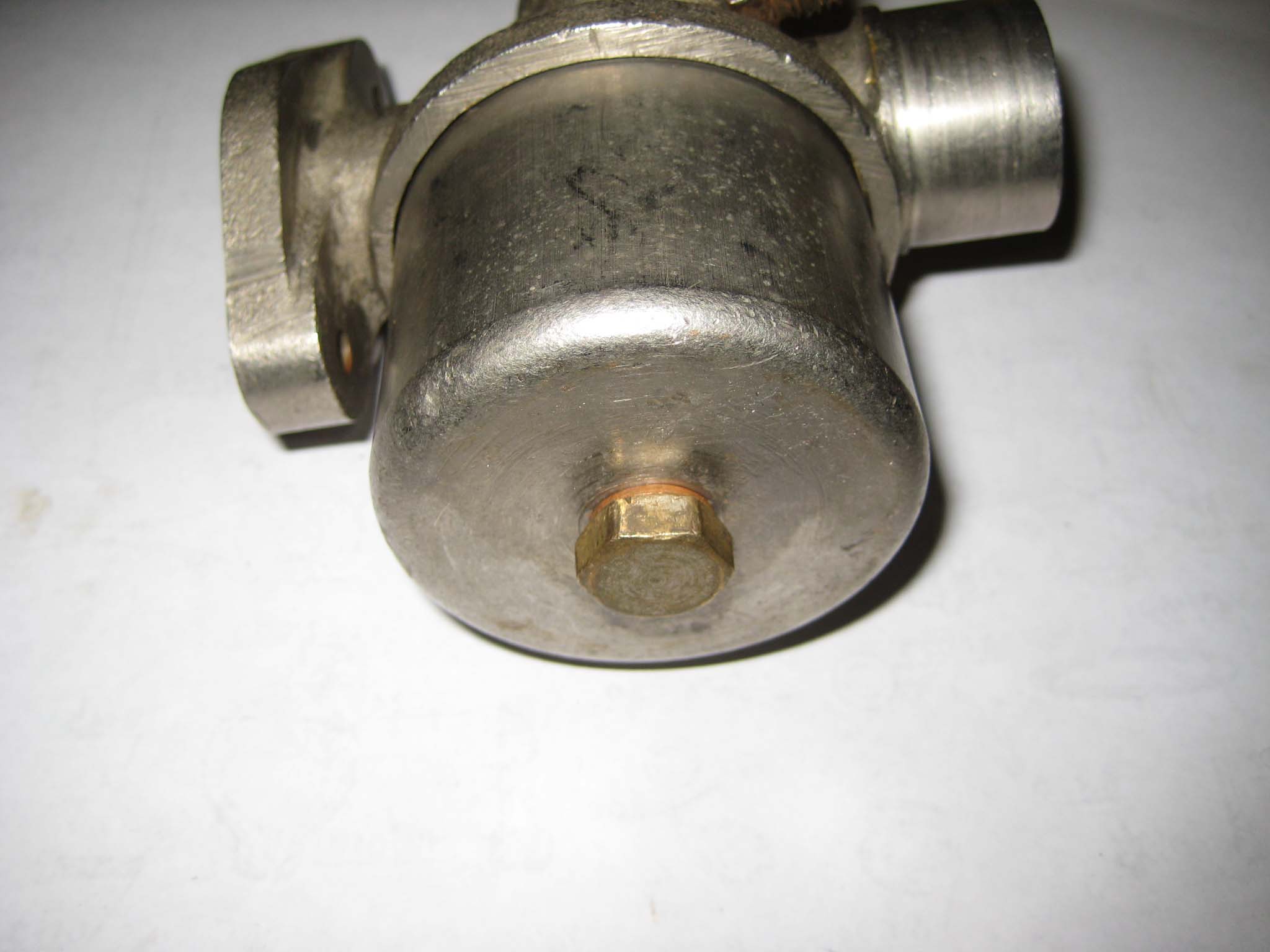
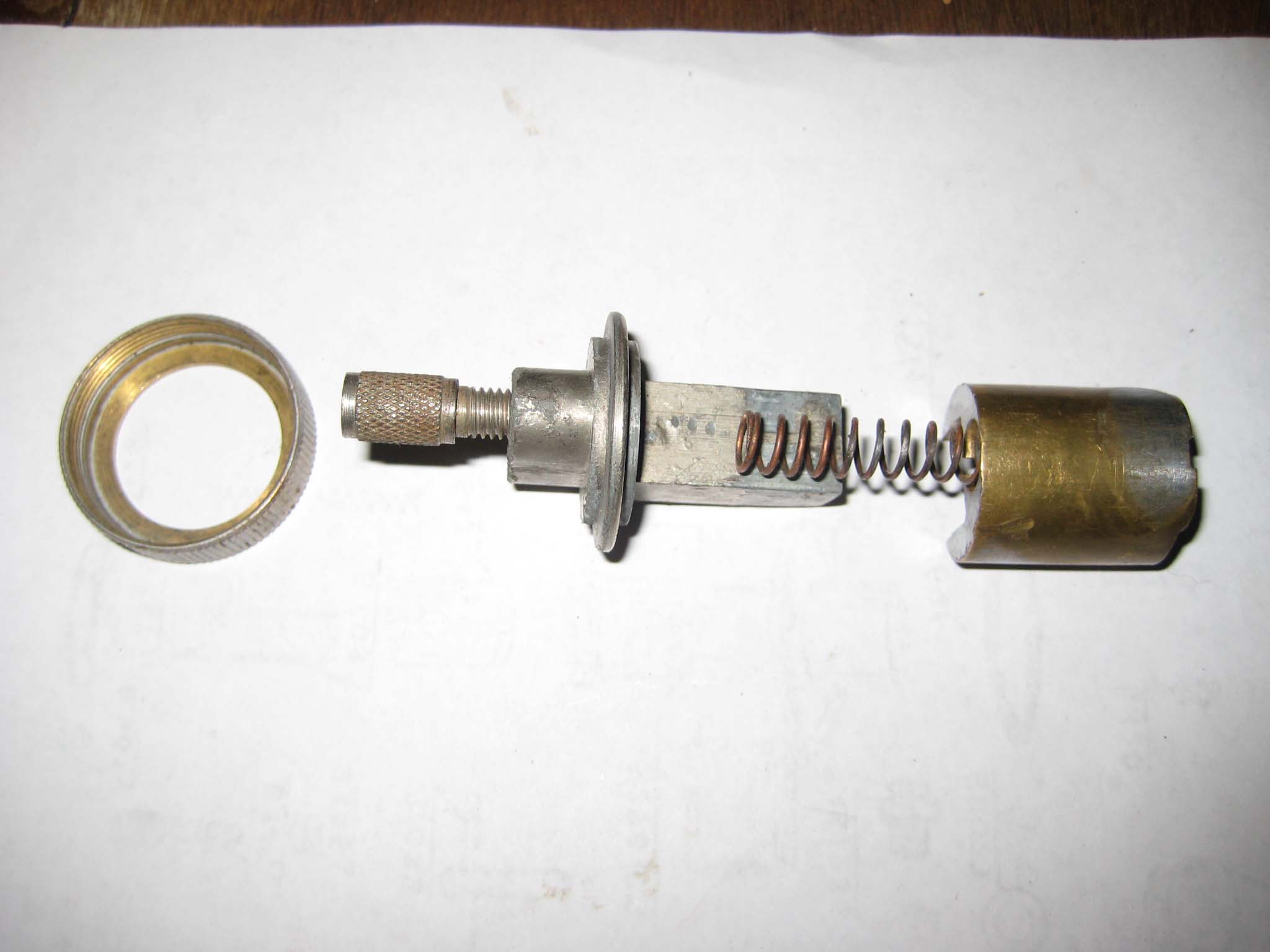
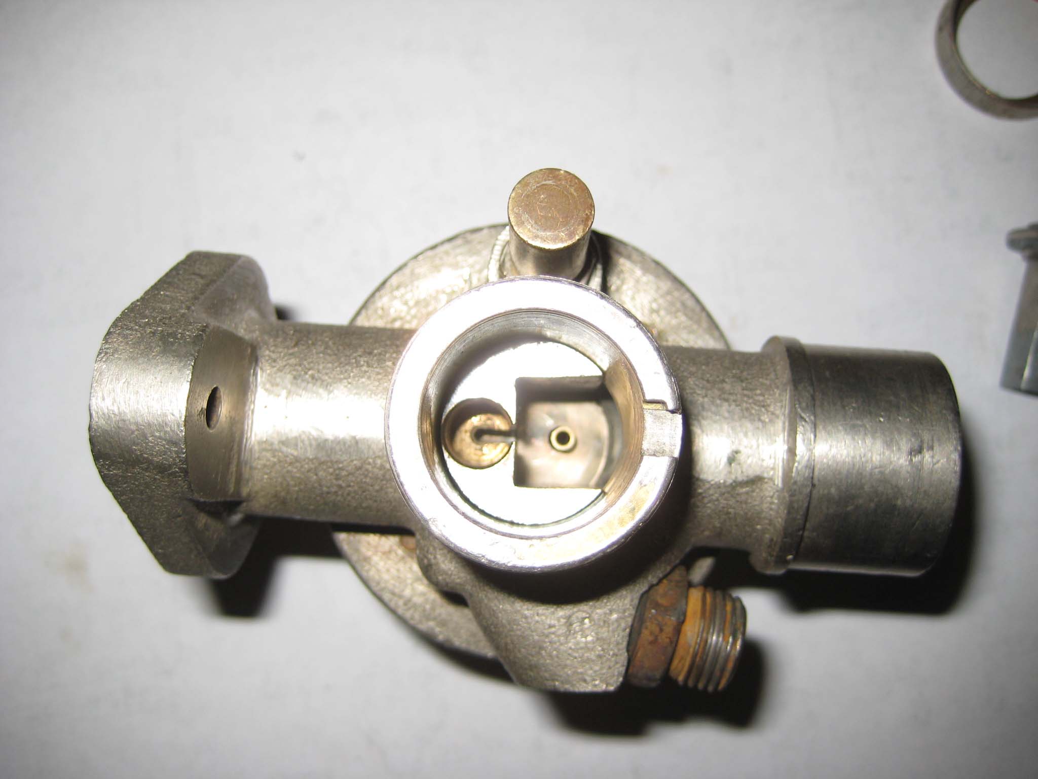
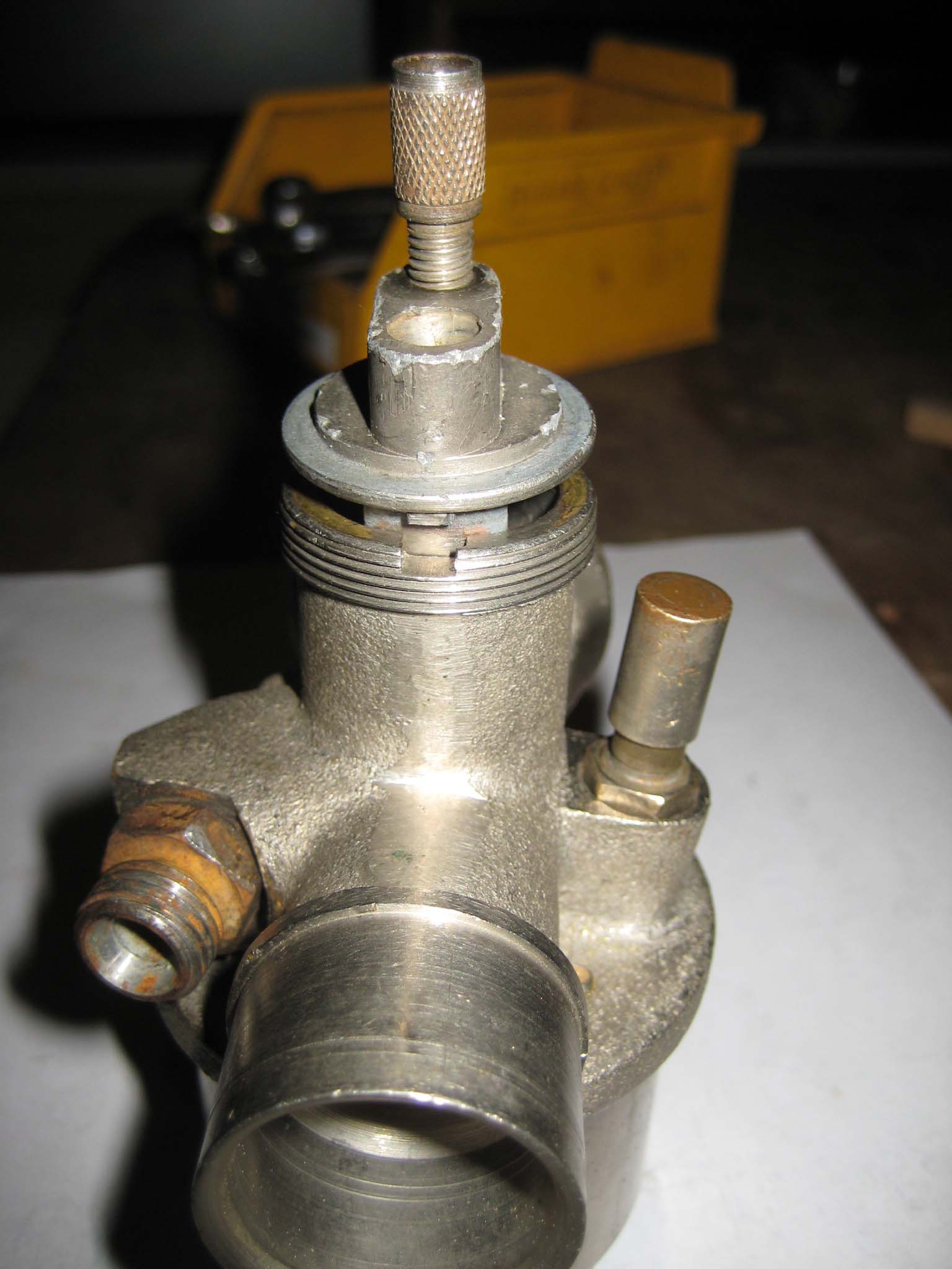
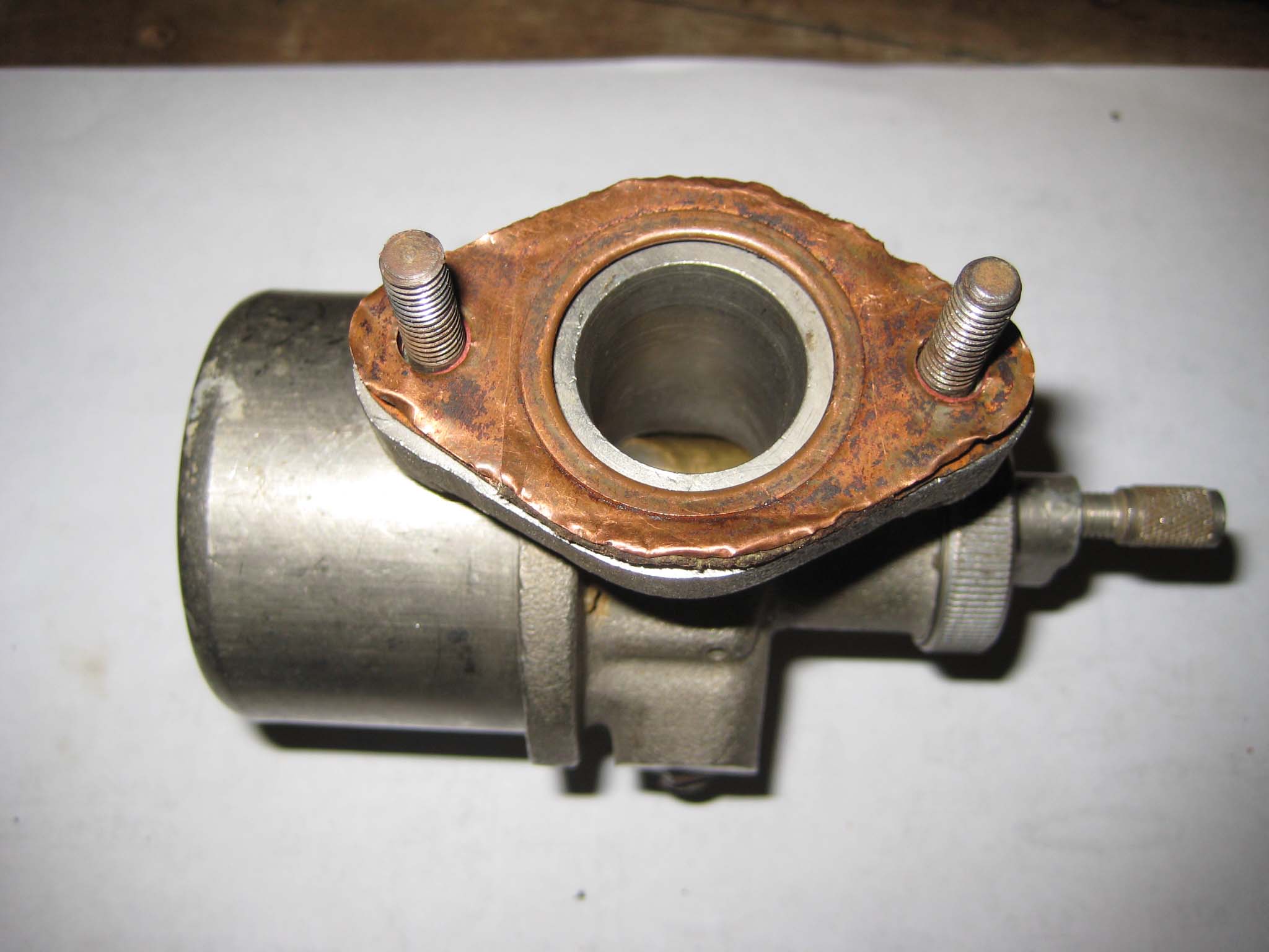
The size 70 main jet had a tubular extension at the inlet end, whereas the size 60 jet from the other carb does not (Carb 0001). I do not know what purpose this extension serves, but as this was the part of the jet that was damaged (Carb 0002), my only option was to cut it off (Carb 0003). A new paper gasket was fitted into the main body of the carb (Carb 0004). The idle and main jets (Carb 0005) were screwed into place using a 5mm square drive radiator key (Carb 0006). Two small slotted head screws hold the paper gasket in place (Carb 0007). Also visible in this picture is the needle holder and needle which allow fuel to enter the float bowl. The large brass plug which covers the jets was screwed into place (Carb 0008). According to the part list, this item is know as the filter adaptor and should have a filter gauze fitted inside it. Neither of my carbs contained this gauze, so currently none is fitted. The fuel supply line nipple was fitted, along with a fibre washer (Carb 0009). On the opposite side of the carb body, the tickler body was screwed into place (Carb 0010) and the tickler inserted through it (Carb 0011). The tickler is held in place by a 1.6mm diameter split pin inserted through the end that projects into the float bowl (Carb 0012). The float and float bowl (Carb 0013) were fixed into place by a bolt and copper washer (Carb 0014). The bolt screws into the filter adaptor, so it is important not to over tighten as damage to the jets could result. The last bits to be fitted were the throttle slide parts (Carb 0015, 16 & 17). I have deliberately left some parts off the throttle, as these will be fitted later with the throttle cable. The carb is fixed to the engine intake/exhaust manifold by two M6 studs and a copper gasket (Carb 0018 & 19). The gasket has seen better days, but it is still usable.Attachments:
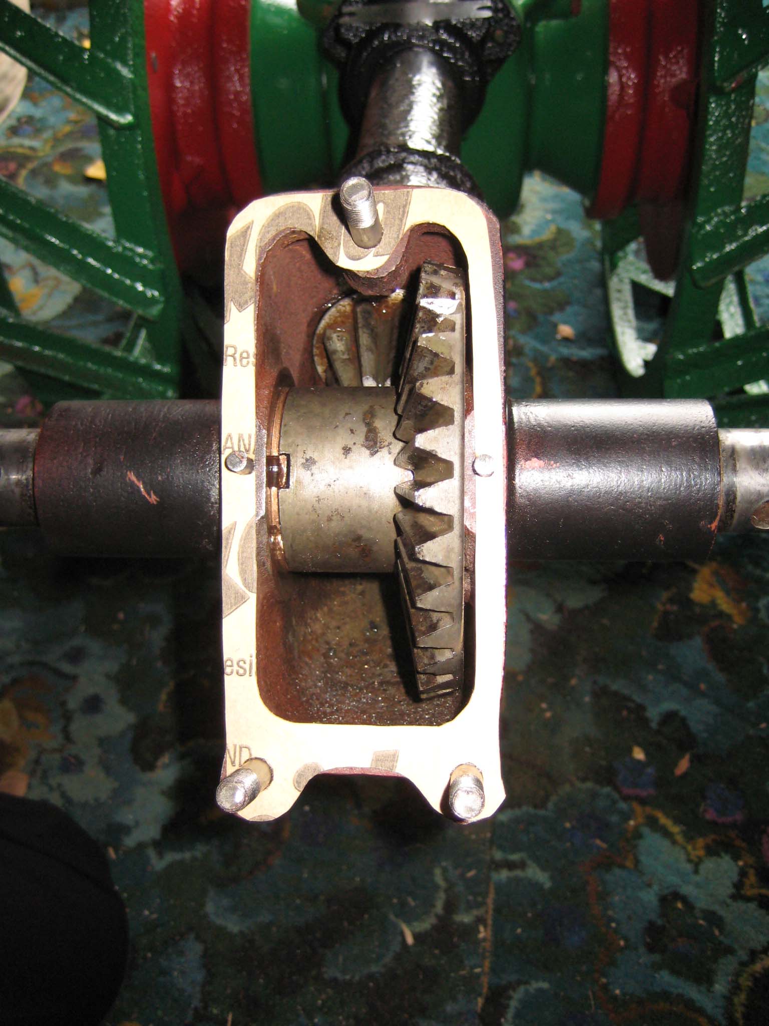
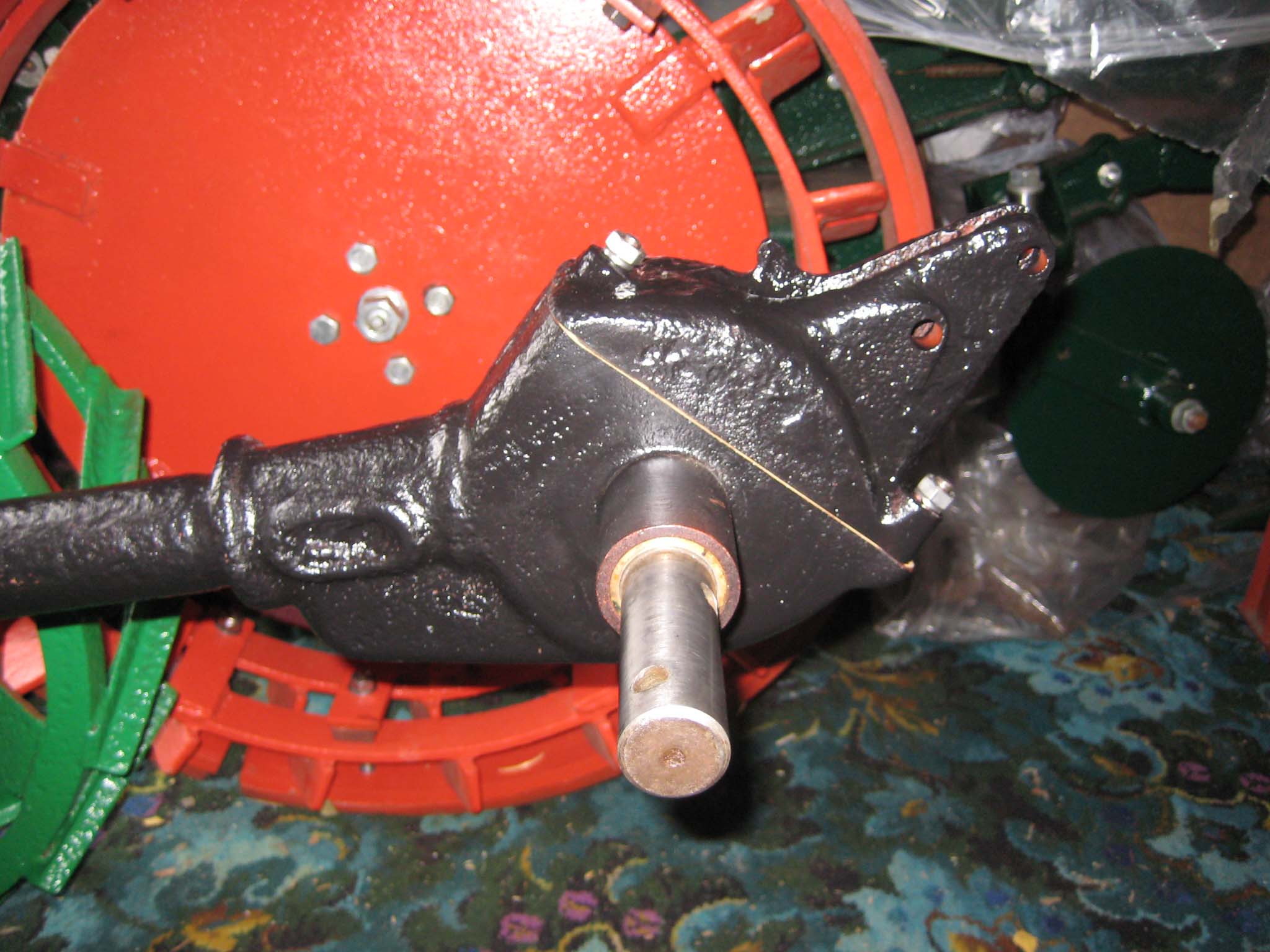
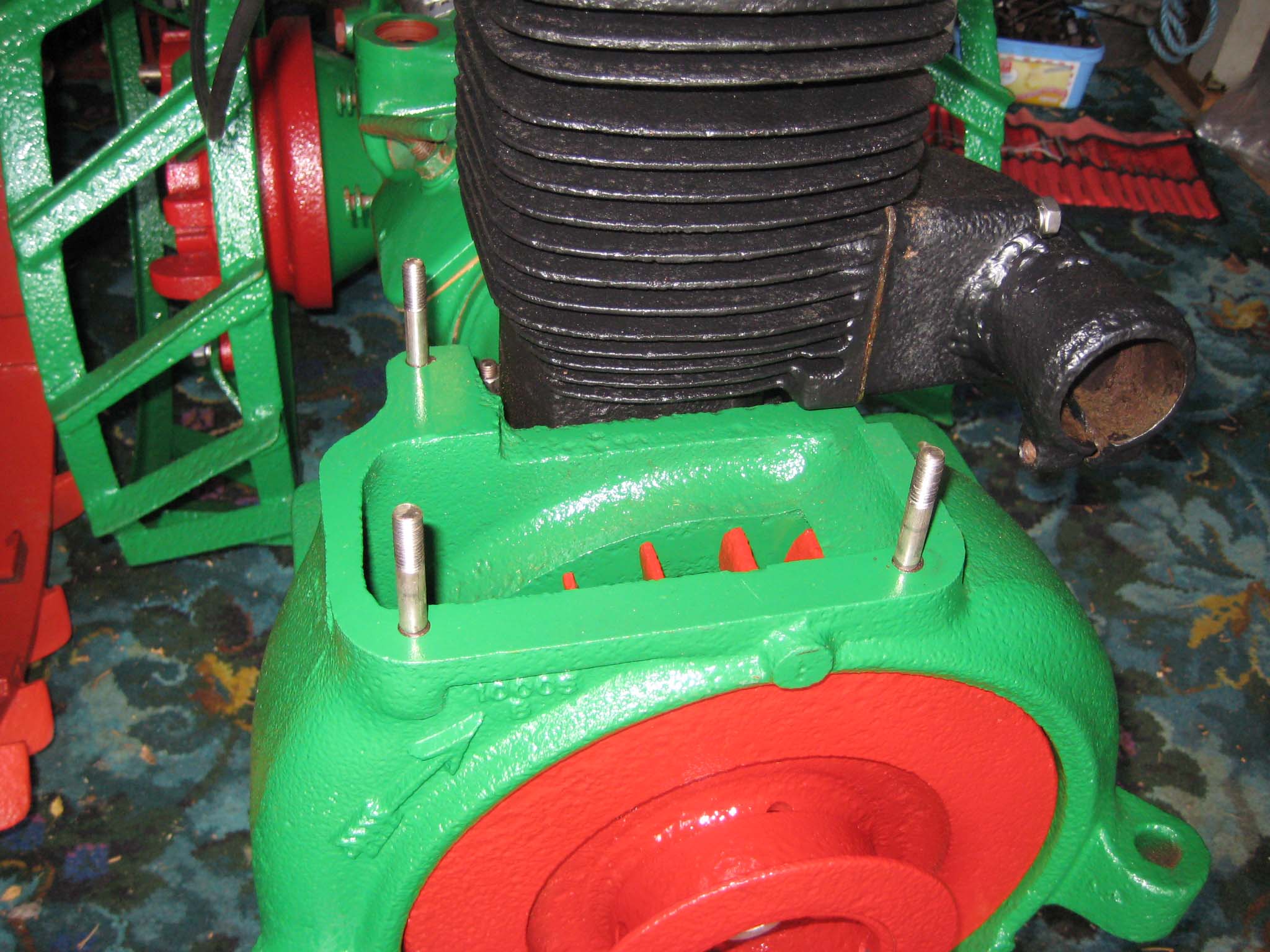
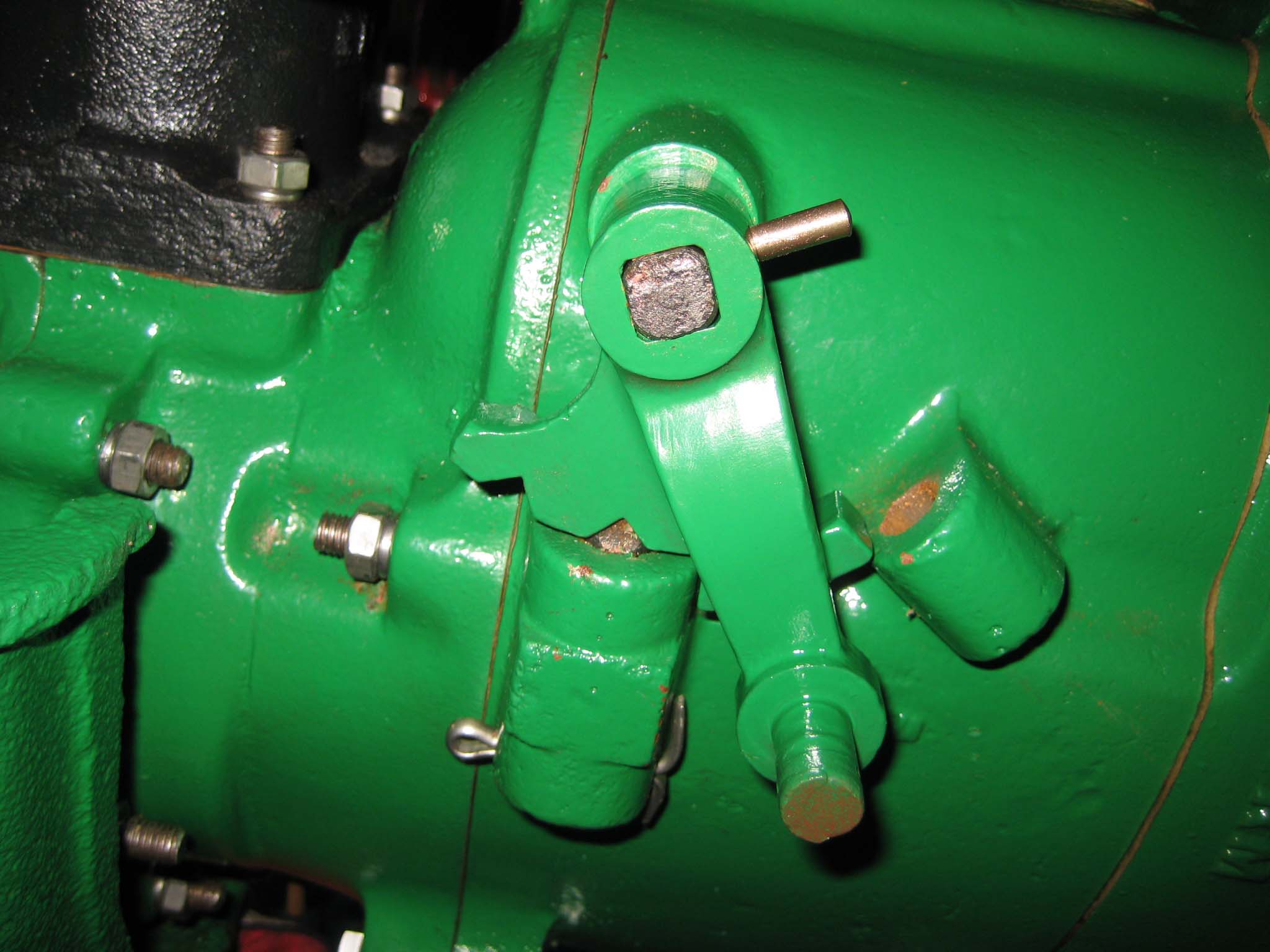
November 7, 2015 at 12:58 pm #15082vhgmcbuddyMemberA new paper gasket was made for the miller gearbox cover and fitted along with the three M8 studs and two locating pins for the miller shaft bronze bushes (Simar 0097), after which the miller gearbox cover was fitted (Simar 0098). Moving back around to the front of the machine, three M8 studs were screwed into the fan casing (Simar 0099) and the engine cowling installed (Simar 0100). Next to be fitted was the reverse motion clutch lever. The lever is held on the shaft by a 5 x 26mm tapered dowel pin (Simar 0101). If removing any of the three clutch levers, it is important that you establish which end of the pin is the larger diameter, so the pin can be driven out in the correct direction i.e. from the smaller end.
Attachments:
November 5, 2015 at 6:42 am #15079vhgmcbuddyMemberThe only way apart from Ebay is machinery sales/local adds. I got two Honda tillers, I used this site to lookup a part and the search the number.
https://www.boats.net/parts/search/Honda/Rototiller/0/parts.htmlOctober 26, 2015 at 6:53 pm #15020vhgmcbuddyMemberHi there I would like to bring my MG2, how does one go about entering the show ?
Swampy.
October 26, 2015 at 11:20 am #15019vhgmcbuddyMemberKeith, Sorry for the delayed reply – I am still getting to grips with ‘messaging’, but thankyou for the information I will have a look next time I am in Maplins.
October 26, 2015 at 11:03 am #15018vhgmcbuddyMemberThey Look great I’ll think on, thanks.
October 26, 2015 at 8:57 am #15009vhgmcbuddyMemberI like the idea of driven wheels, also I used to use my Dad’s Bantam as a teenager on his smallholding along with several other interesting machines, jobber, farmers boy etc, so it’s also a bit of nostalgia. Thanks for taking the time to give me the info. I’ll have to keep my eyes open.
Shaun
October 25, 2015 at 10:55 pm #15007vhgmcbuddyMemberHow does that compare in size to the Bantam?
October 25, 2015 at 10:50 pm #15006vhgmcbuddyMemberHi that would be great thanks.
October 25, 2015 at 4:59 pm #15003vhgmcbuddyMemberGot my copy Friday, proper job Mister Editor sir !!
More articles and photos to follow Alan…
October 25, 2015 at 4:57 pm #15002vhgmcbuddyMemberWe will be there either Saturday or Sunday, visiting only this year, will come and find you all on the club stand!
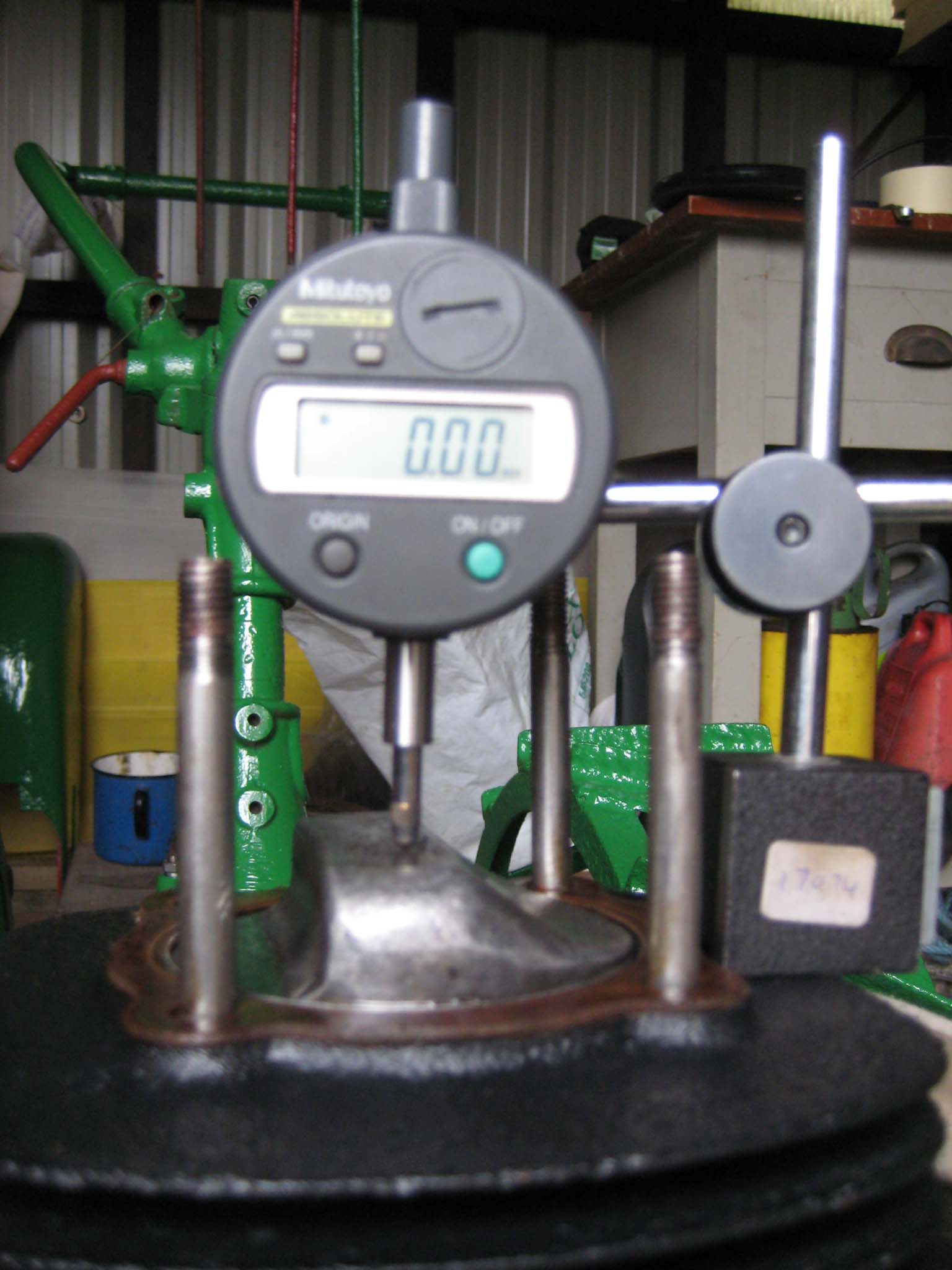
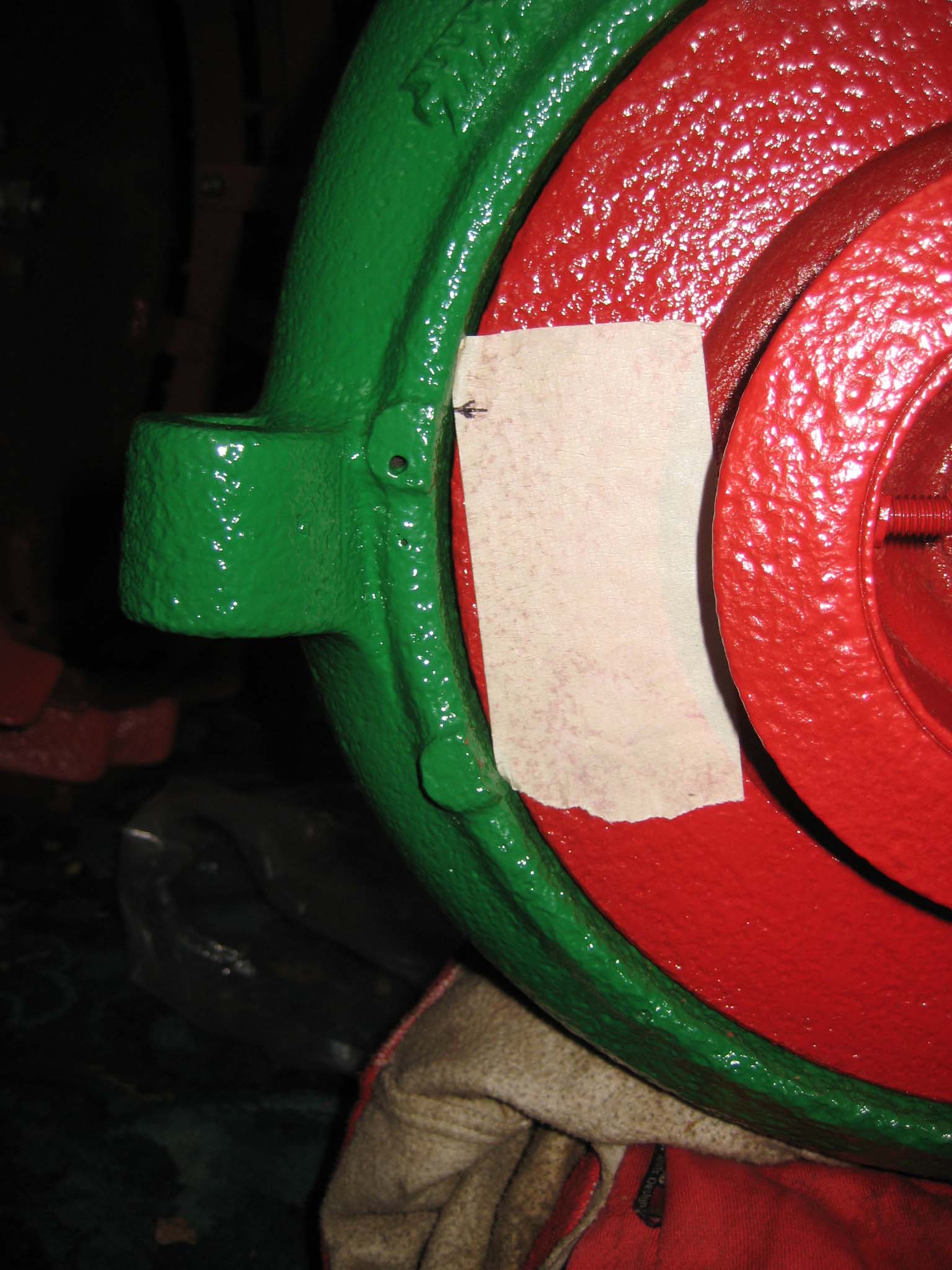
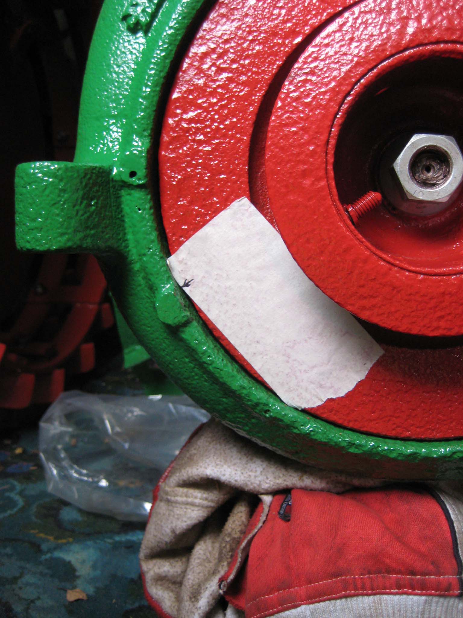
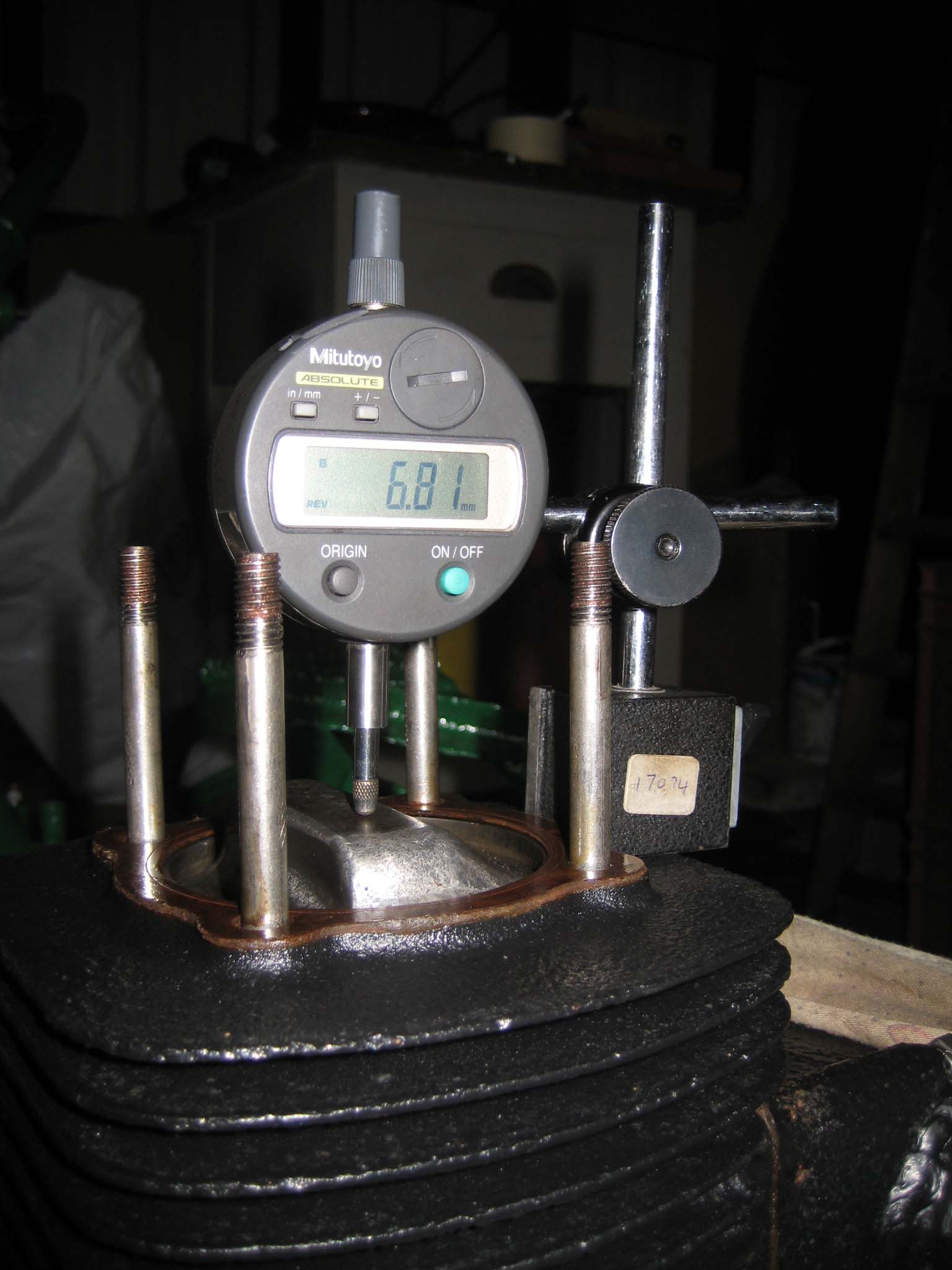
October 24, 2015 at 11:48 am #14980vhgmcbuddyMemberTo refit the magneto, I first needed to ensure that the piston was positioned at the point the magneto contact breaker would begin to open. I removed the cylinder head so I could use a dial test indicator to establish top dead centre (Simar 0092). I then marked the cooling fan adjacent to a lump on the right of the fan casing (Simar 0093). The fan was rotated anti-clockwise until the mark lined up with another lump on the fan casing (Simar 0094). The amount rotated was 68mm measured around the circumference of the fan. The reading on the dial test indicator showed that the piston had dropped by 6.8mm (Simar 0095), a factor of 10 less than the distance measured around the fan circumference. Coincidence or clever design?
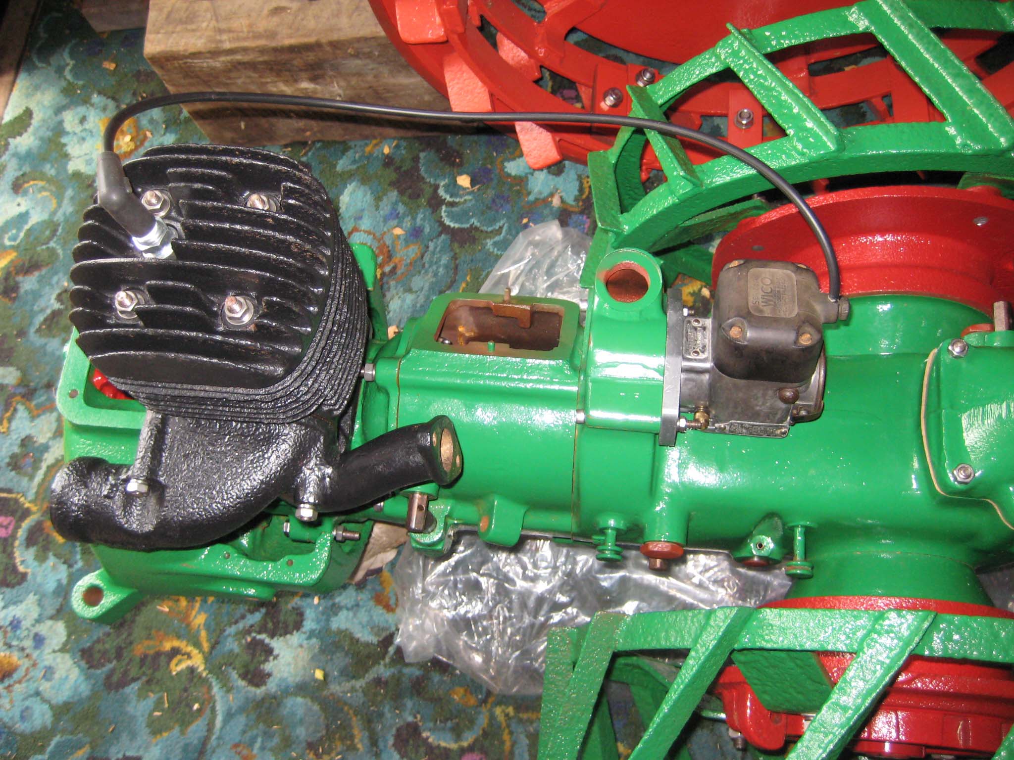
I set the magneto up with the points just starting to open and then bolted it to the main gearbox (Simar 0096). The mounting plate on the magneto has slotted holes, so fine tuning of the timing can be done by slackening the bolts and rotating the magneto.Attachments:
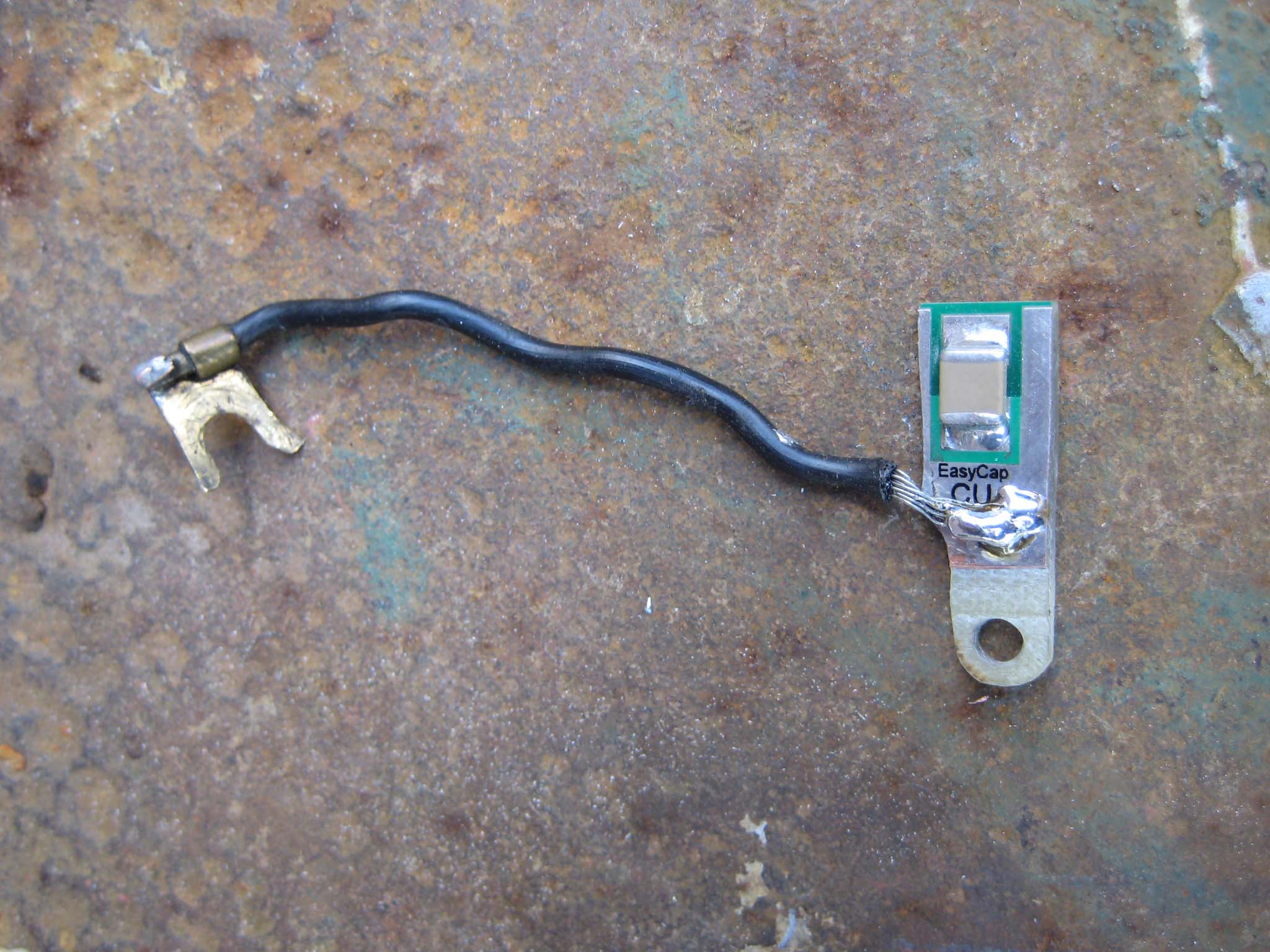
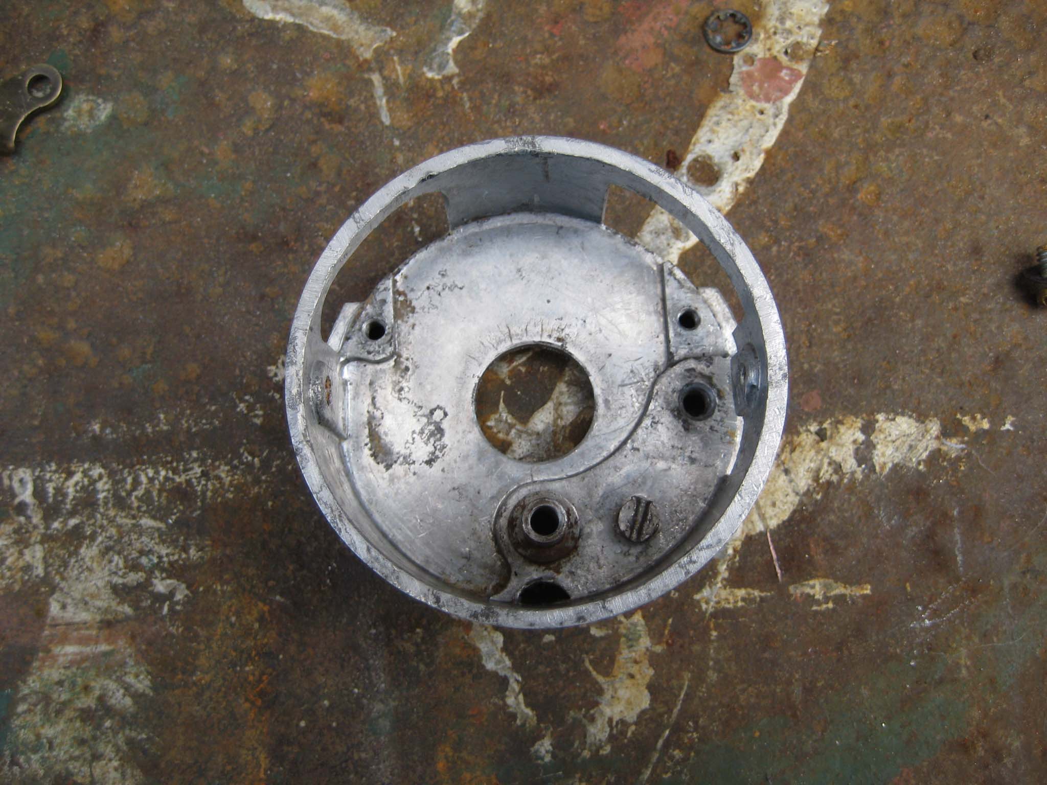
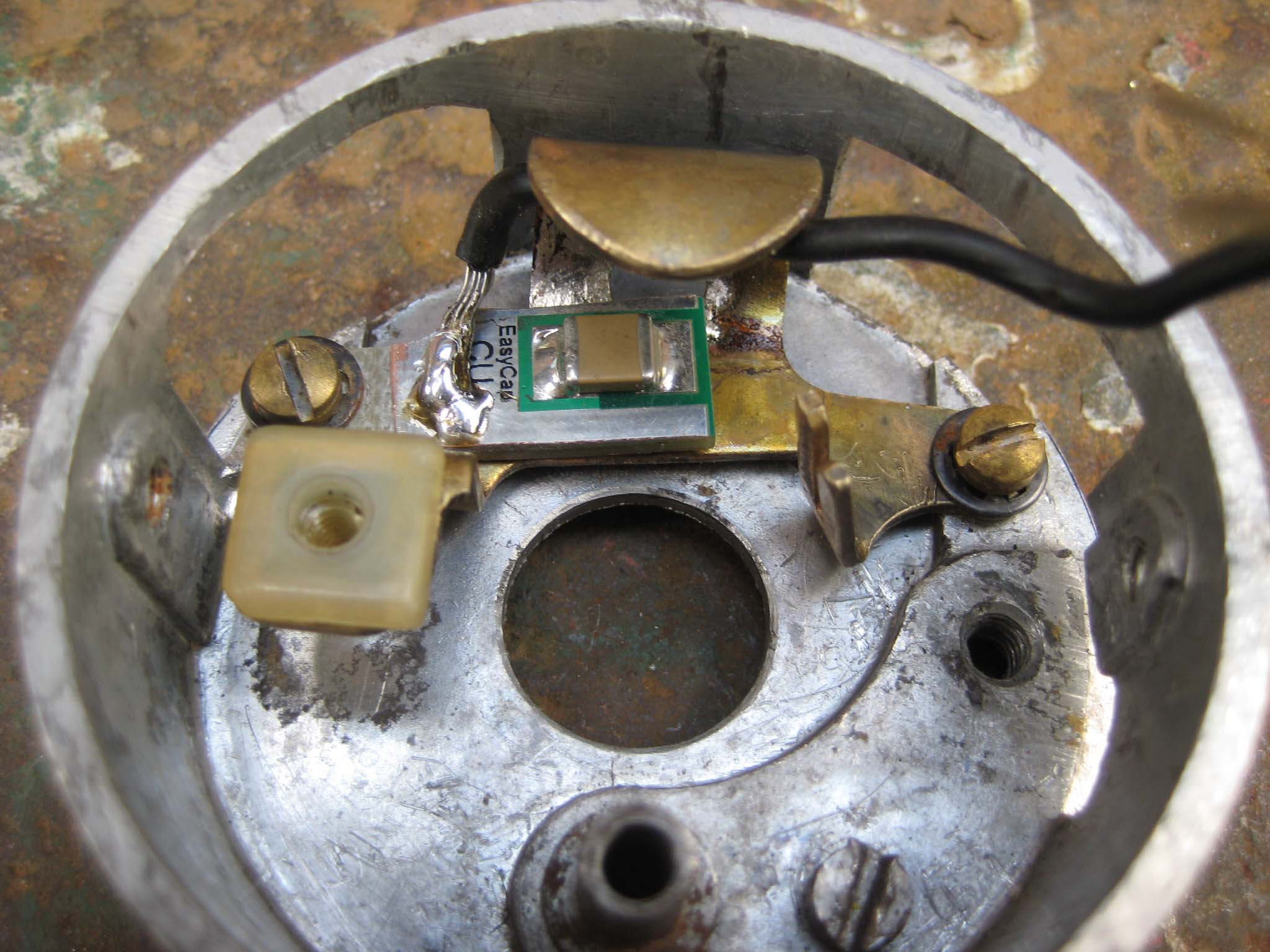
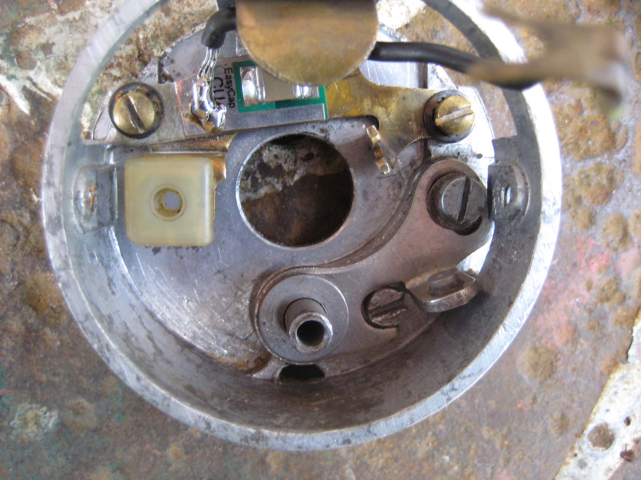
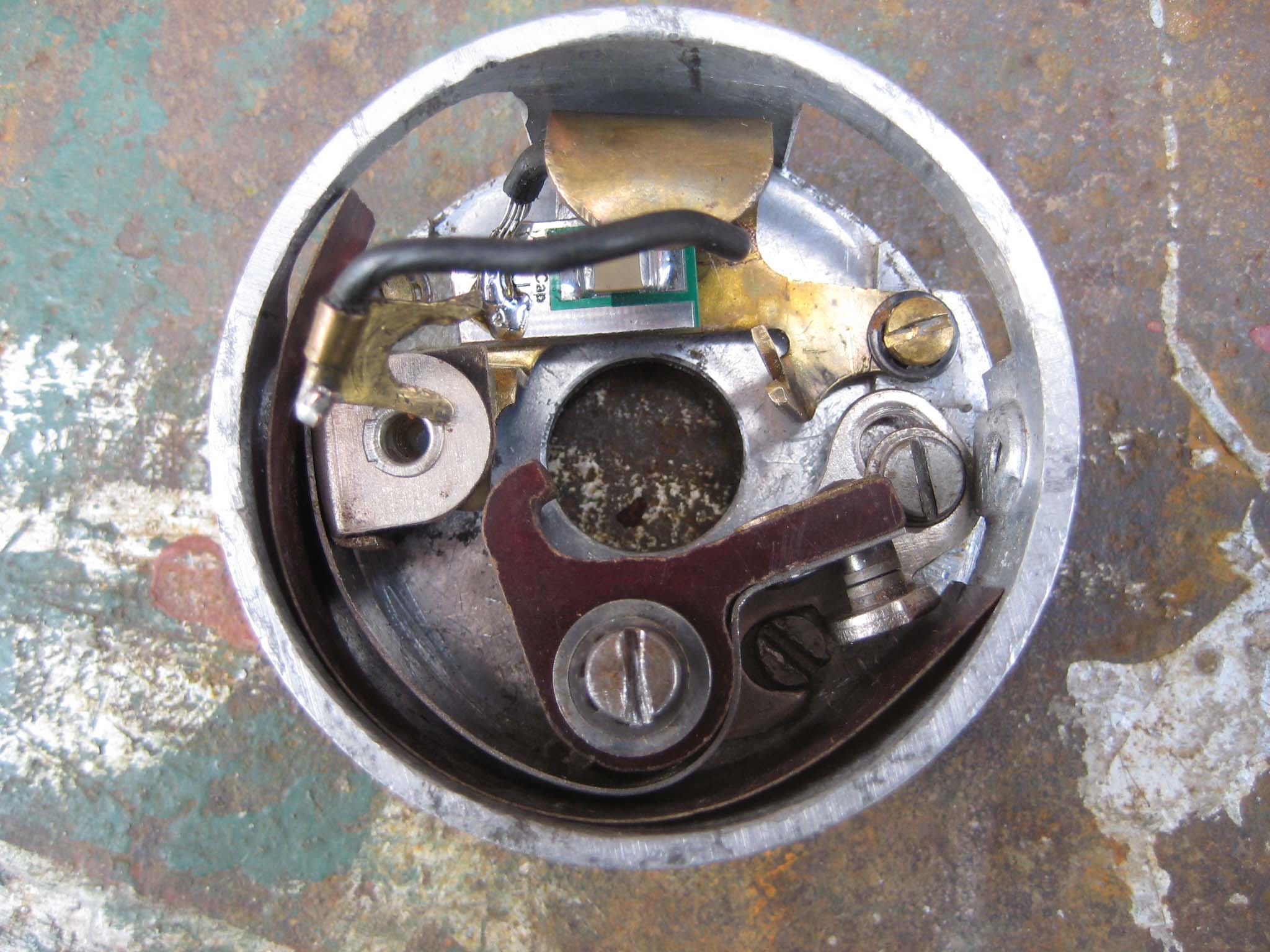
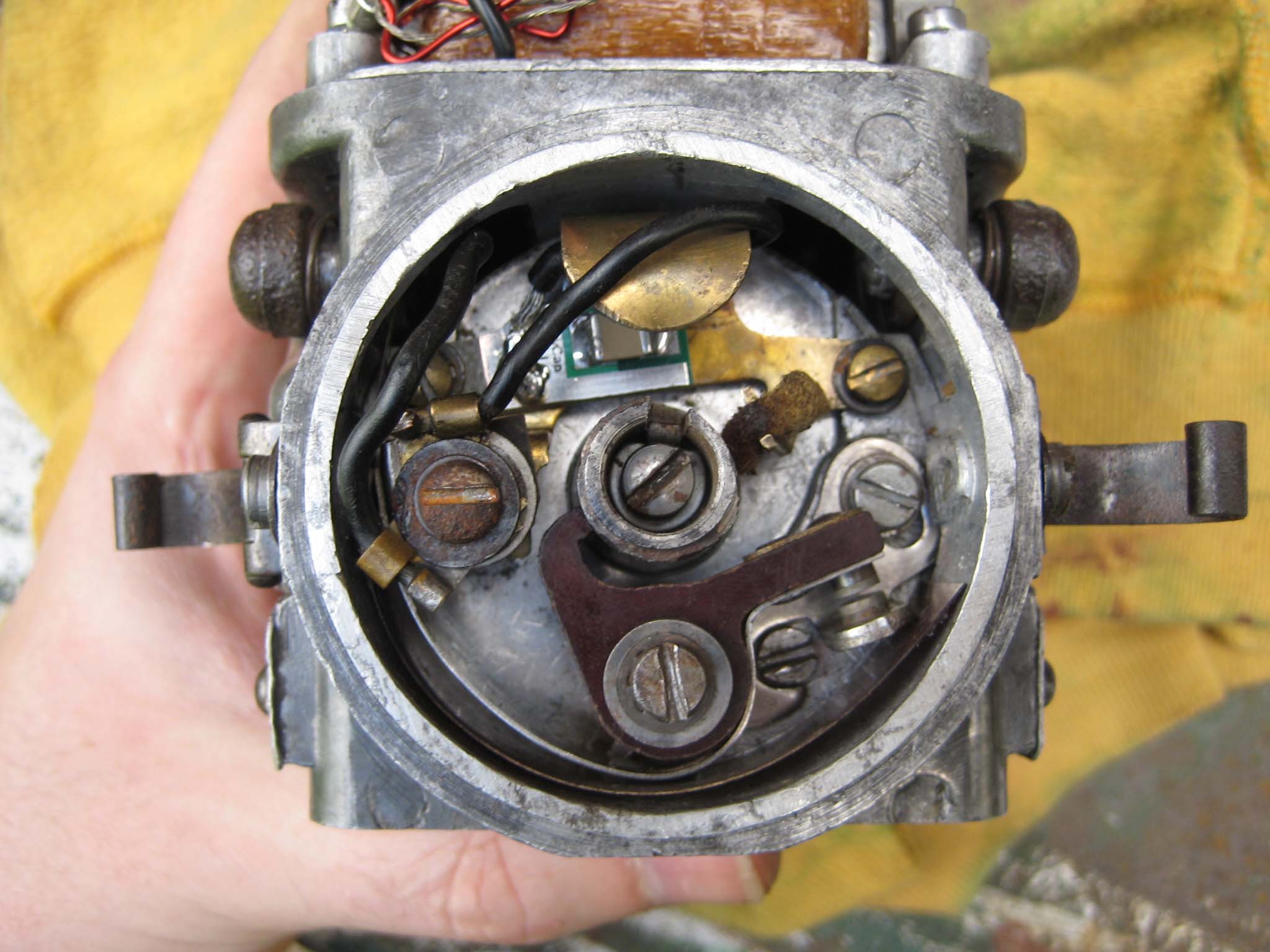
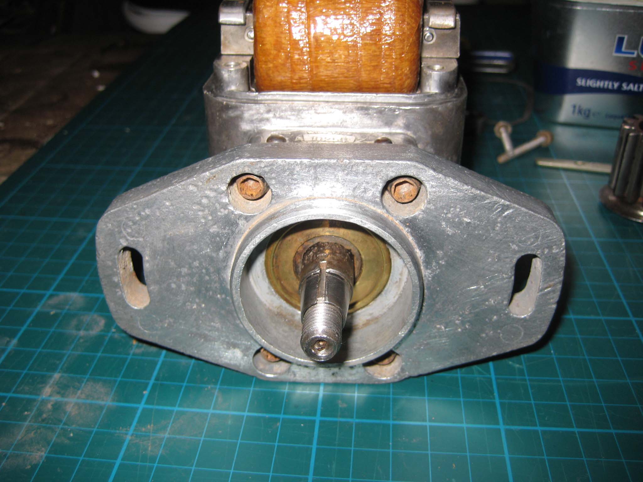
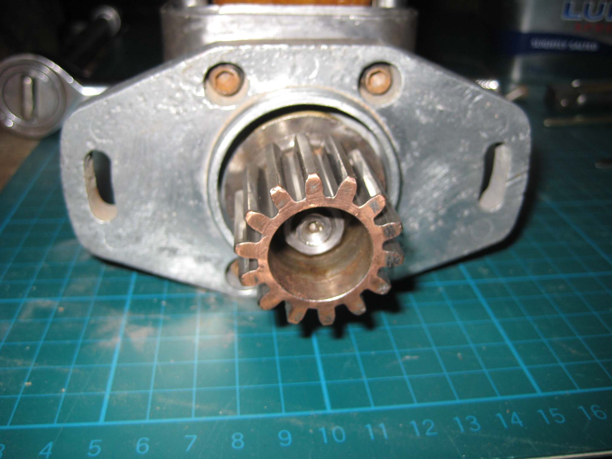
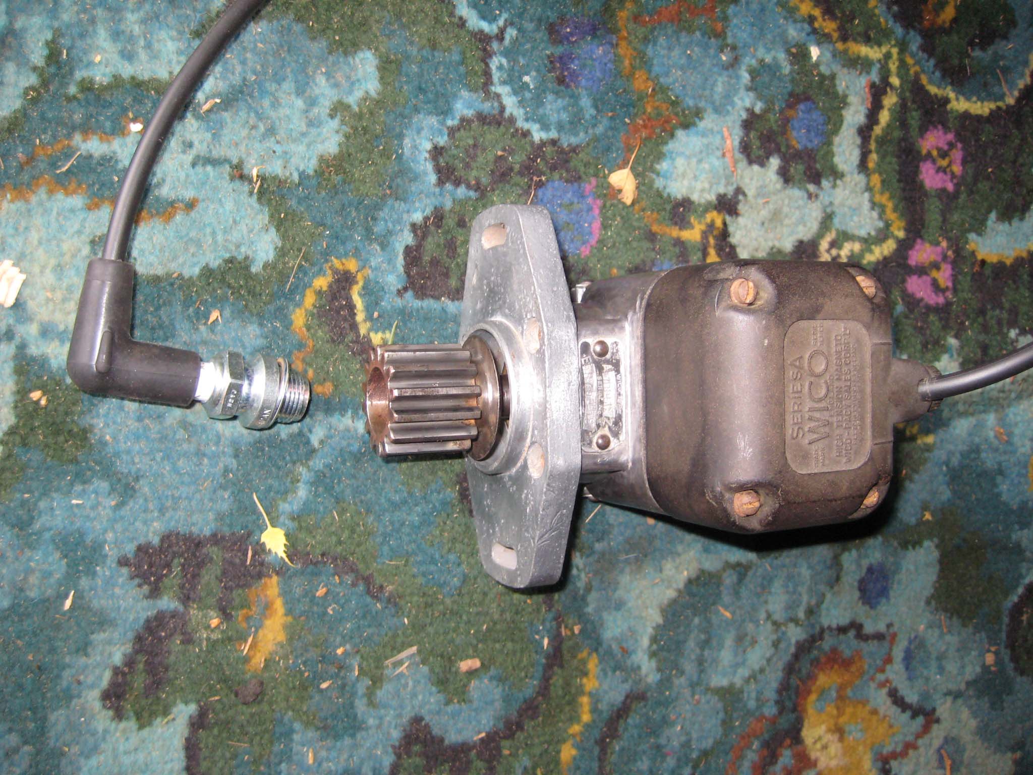
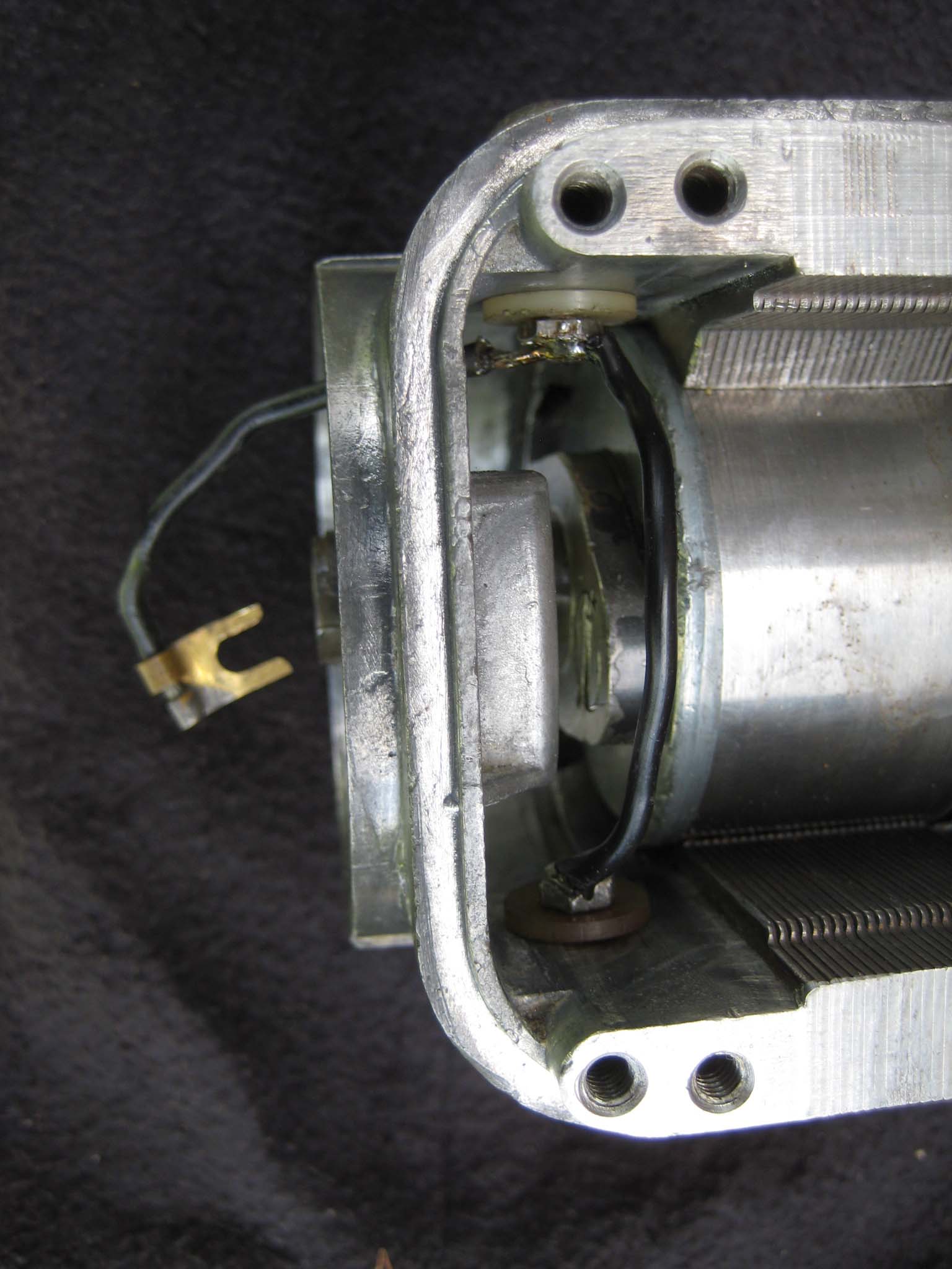
October 24, 2015 at 11:44 am #14969vhgmcbuddyMemberI had already decided that the original condenser would be replaced by an EasyCap condenser from Brightspark Magneto’s. To do this, the original condenser was unsoldered from it’s mounting bracket (Mag 0014). The EasyCap condenser was cut to size so that it would fit onto the condenser mounting bracket and the fly lead soldered in place (Mag 0015). The breaker box was cleaned (Mag 0016) and the condenser and mounting bracket fitted (Mag 0017). The fixed contact went in next (Mag 0018), followed by the breaker arm and strip of insulation around the inside lower half of the breaker box (Mag 0019). The breaker box was then slid back into the main housing, taking care not to trap any wires. The breaker box is clamped into place by the fixing screw which hold the front cover spring clips. The wiring was connected up to the condenser mounting bracket and the felt pad for the cam inserted into the fork in the condenser bracket (Mag 0020). The mounting flange complete with oil seal pressed into the centre was bolted to the main housing (Mag 0021). The drive gear fits on the rotor shaft tapered collar (Mag 0022). The gear is not keyed to the shaft. To complete the job, a new copper HT lead was fitted to the cover along with a NGK AB-6 spark plug (Mag 0023). End result is a fat, Blue spark, even at low speed.
Attachments:
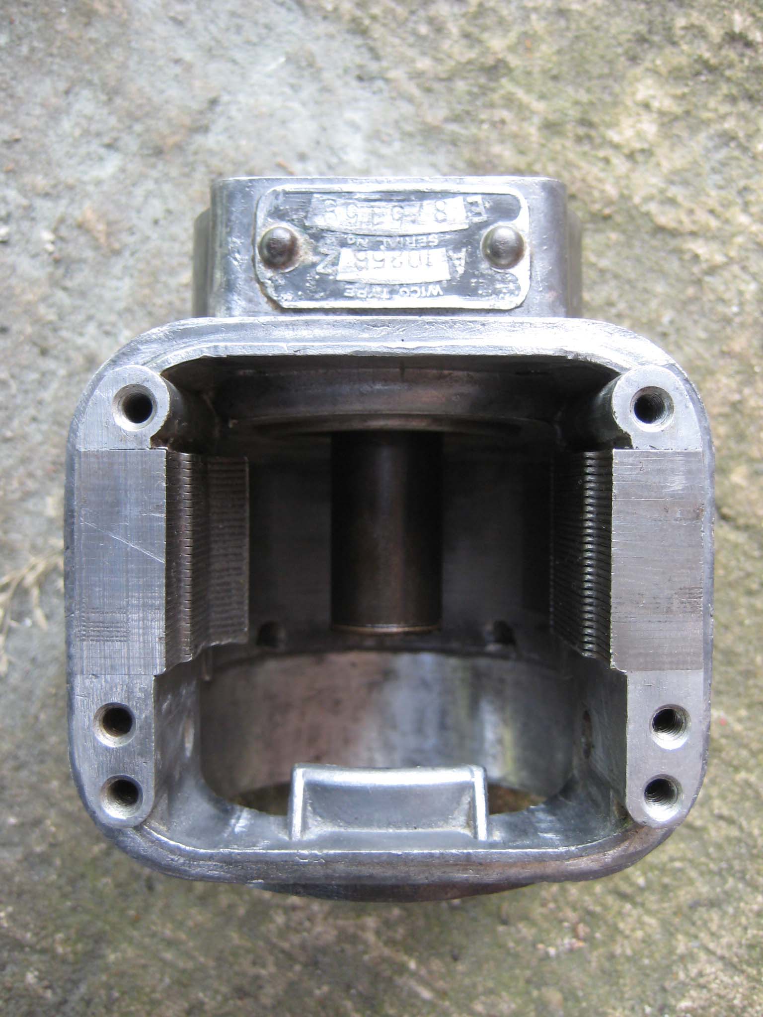
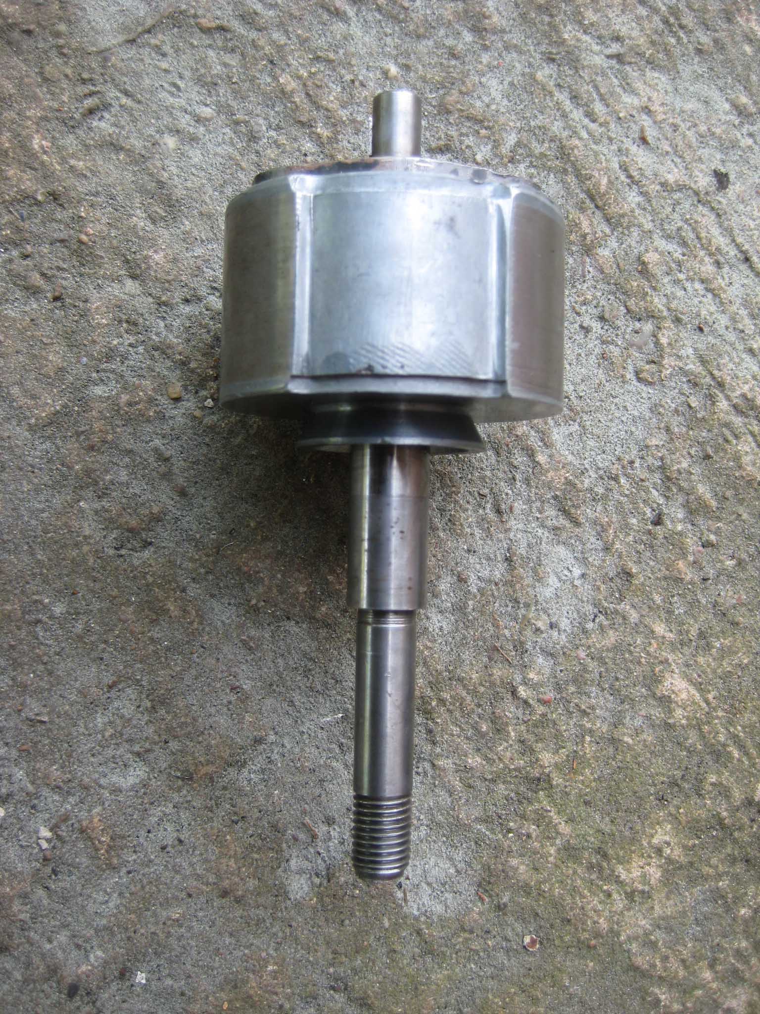
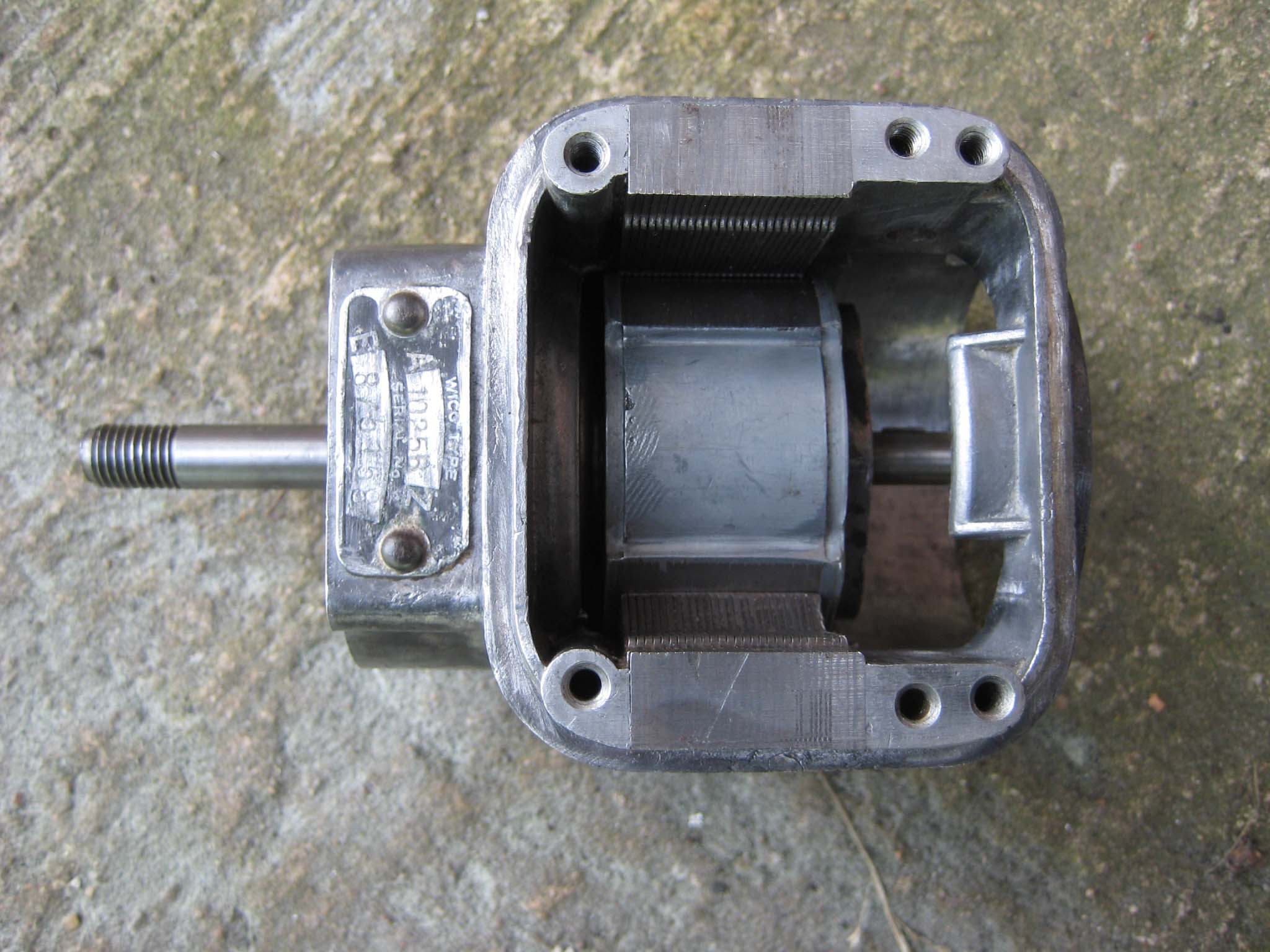
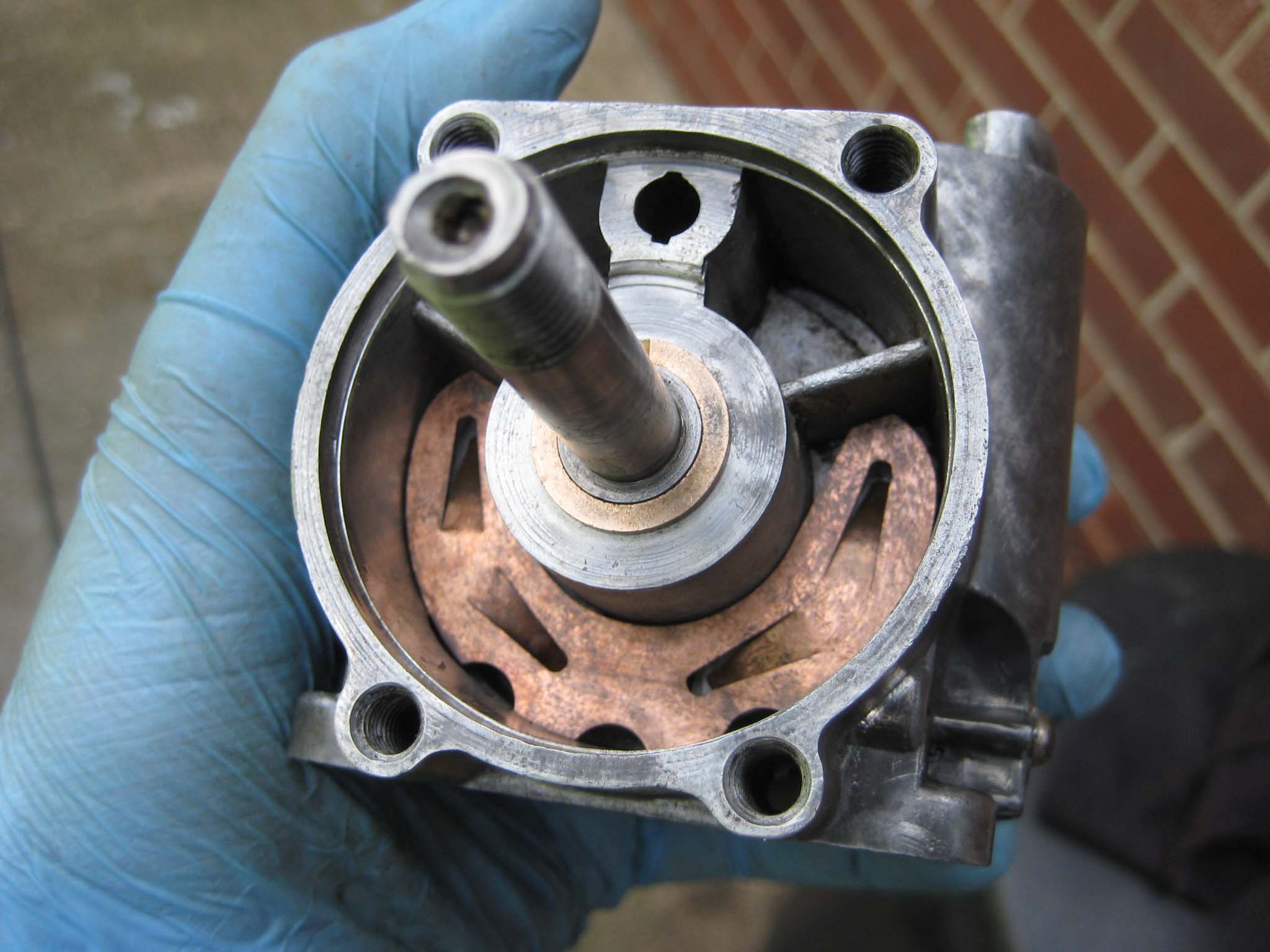
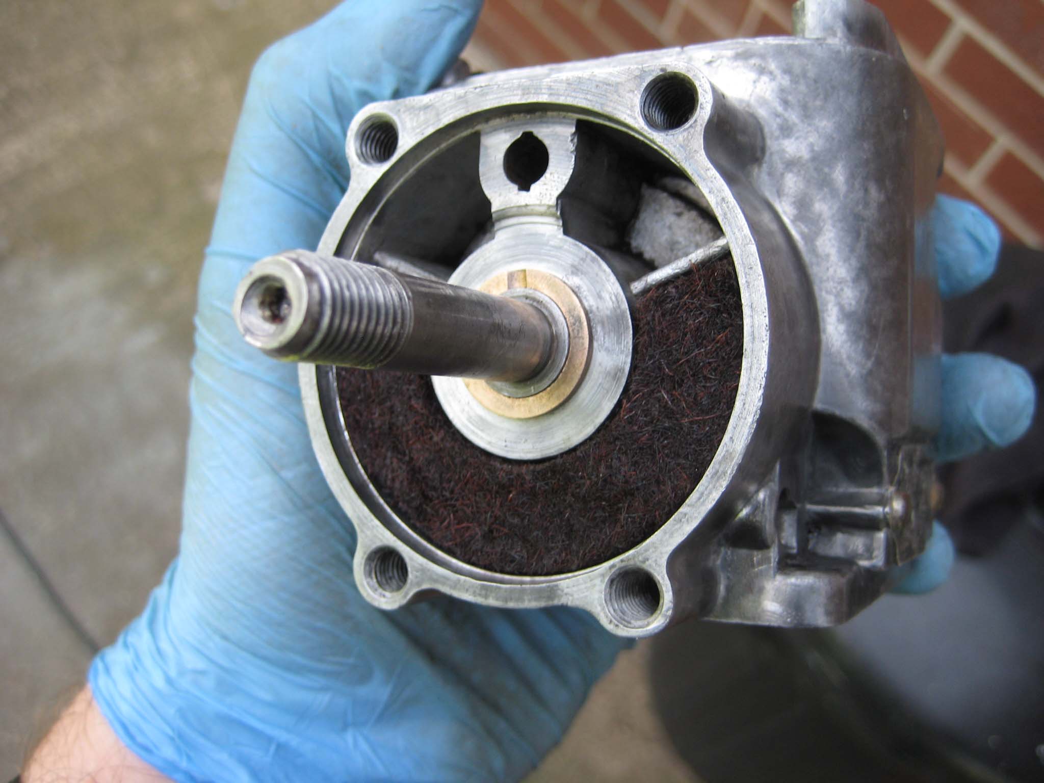
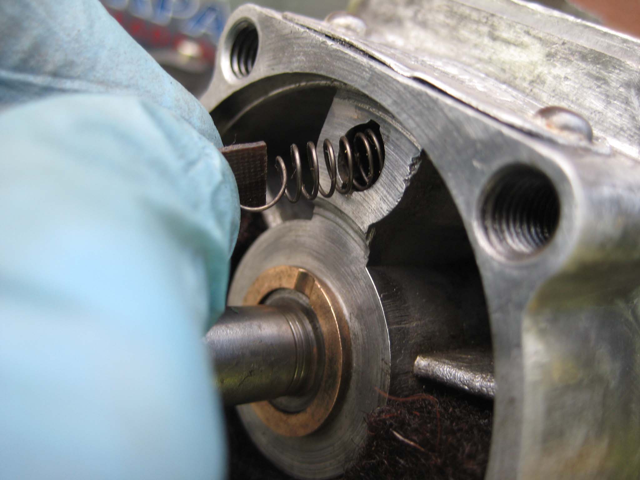
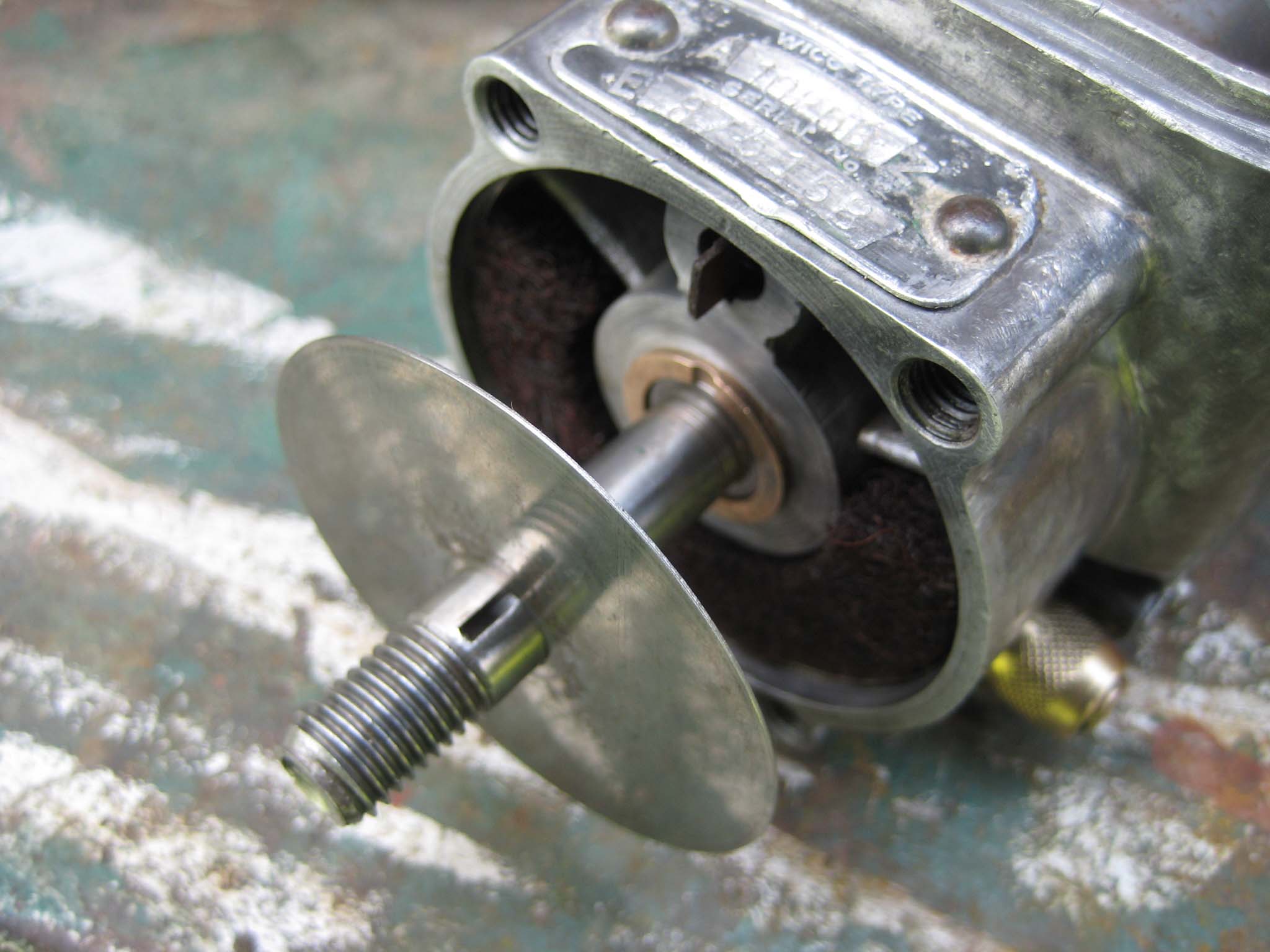
October 24, 2015 at 11:39 am #14955vhgmcbuddyMemberI now focused my attention on the magneto. My Simar 56a is fitted with a Wico Series A magneto, type A10258Z. I took the plunge and decided to treat it to a full strip down and refurbishment. The following details the rebuild.
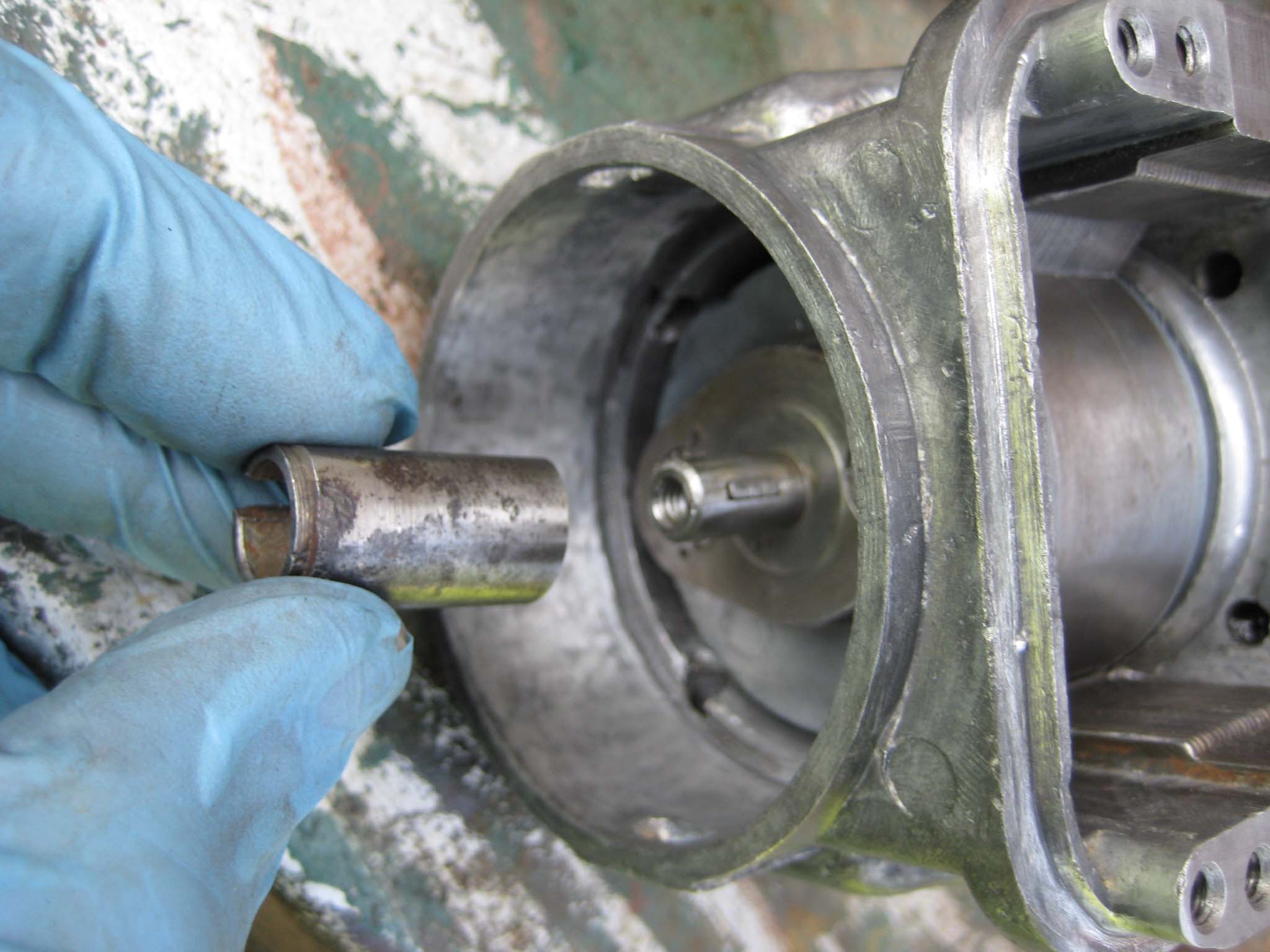
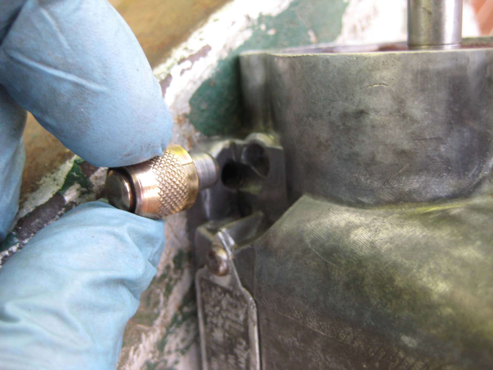
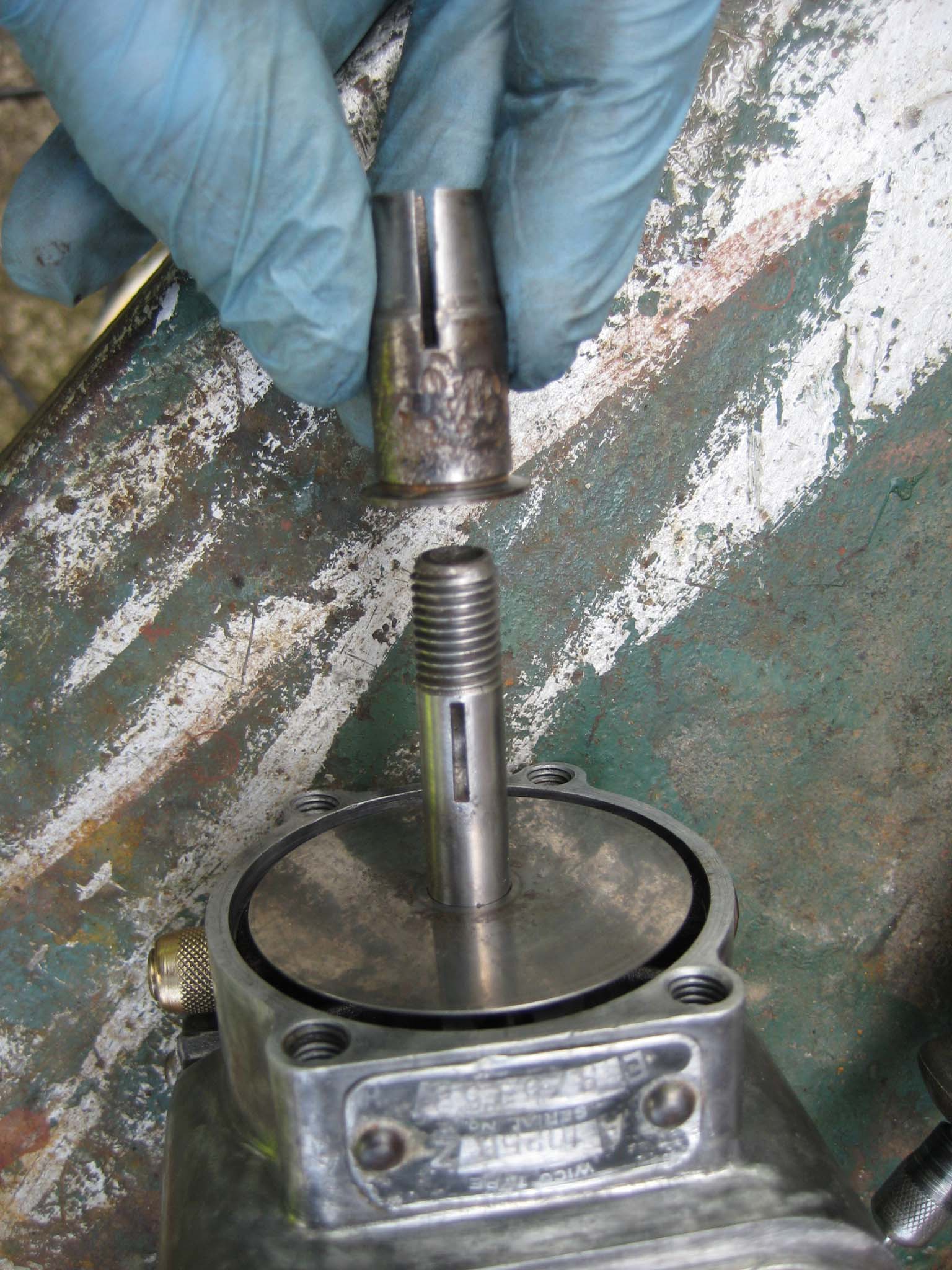
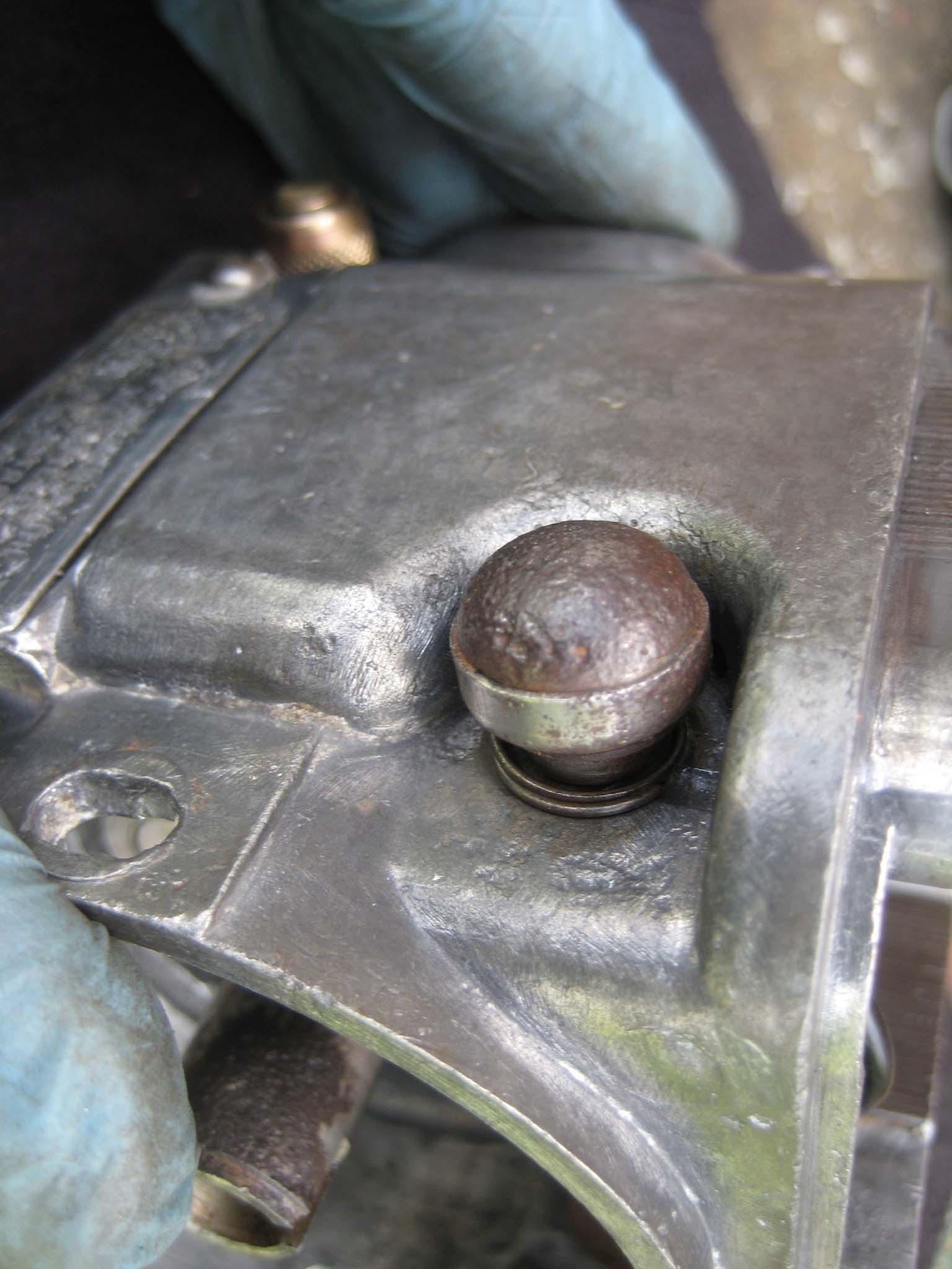
The main housing was cleaned (Mag 0001) in preparation for the rotor (Mag 0002). With the rotor back in the main housing (Mag 0003), the cam which operates the points was attached to the rotor via a half moon key (Mag 0004). The oil pad spring (Mag 0005), oil pad (Mag 0006) and sprung oil scraper assembly (Mag 0007) were fitted. The Brass oilers are a push fit into holes in the main housing (Mag 0008). To complete the lubrication system, the oiling disc was slid over the rotor shaft (Mag 0009). The Simar does not have an impulse coupling on the magneto to aid starting, instead having a tapered collar which is keyed to the rotor shaft (Mag 0010) onto which the drive gear will be installed later. The stop buttons (Mag 0011) were attached to the main housing, making sure not to forget the insulating washers that fit on the inside of the housing (Mag 0012). A new coil was fitted (Mag 0013) before moving on to the points.
Attachments:
-
AuthorPosts