
Forum Replies Created
-
AuthorPosts
-
October 25, 2015 at 10:50 pm #15006vhgmcbuddyKeymaster
Hi that would be great thanks.
October 25, 2015 at 4:59 pm #15003vhgmcbuddyKeymasterGot my copy Friday, proper job Mister Editor sir !!
More articles and photos to follow Alan…
October 25, 2015 at 4:57 pm #15002vhgmcbuddyKeymasterWe will be there either Saturday or Sunday, visiting only this year, will come and find you all on the club stand!
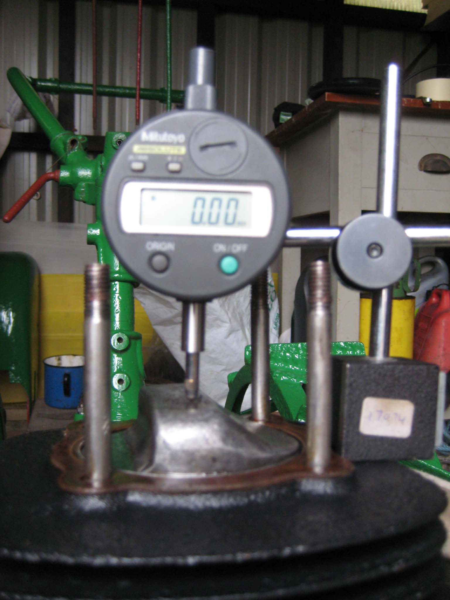
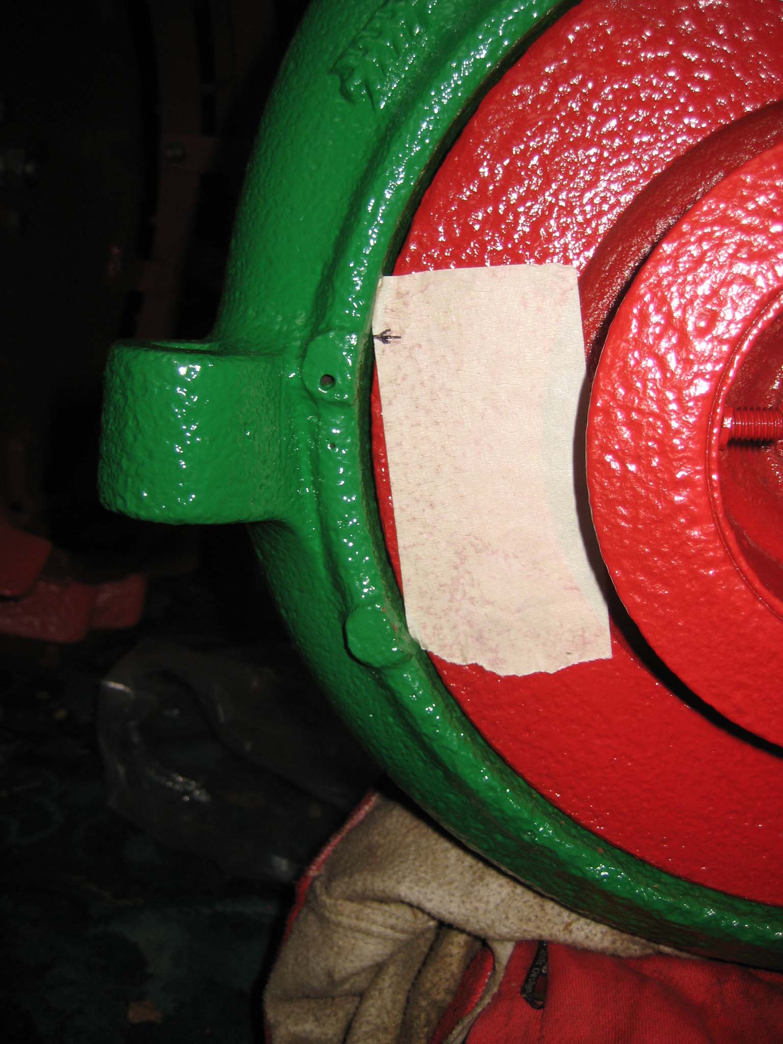
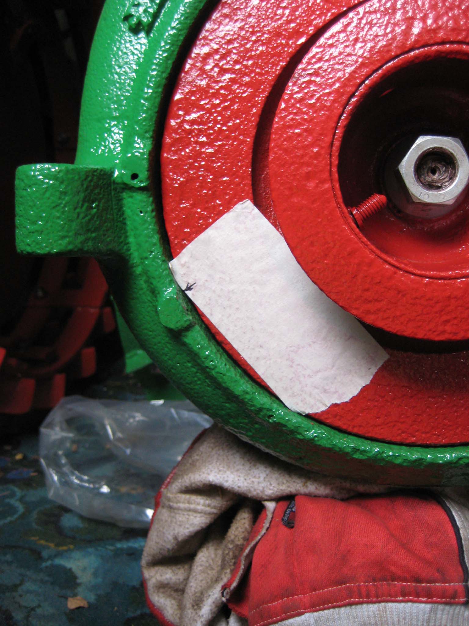
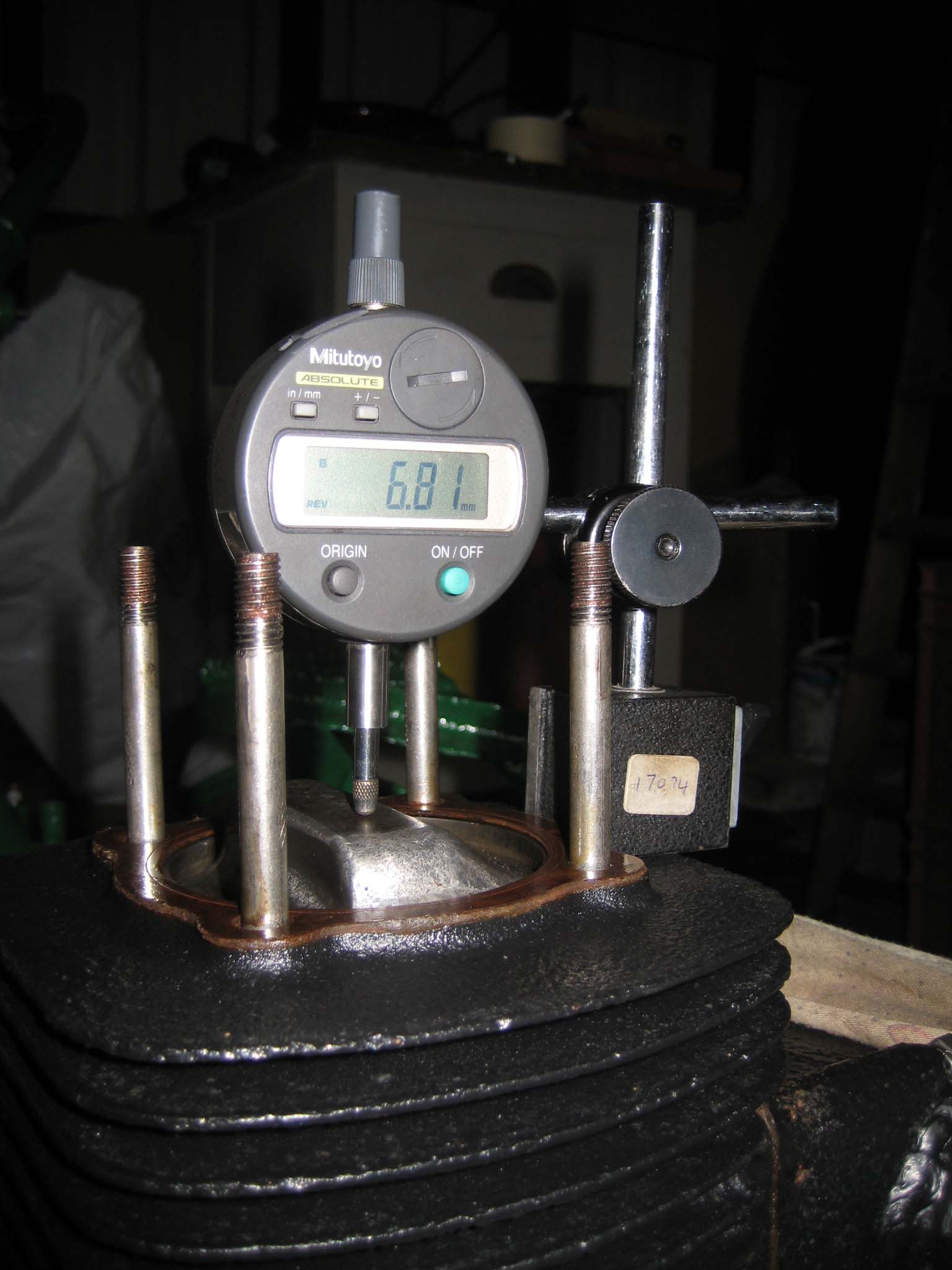
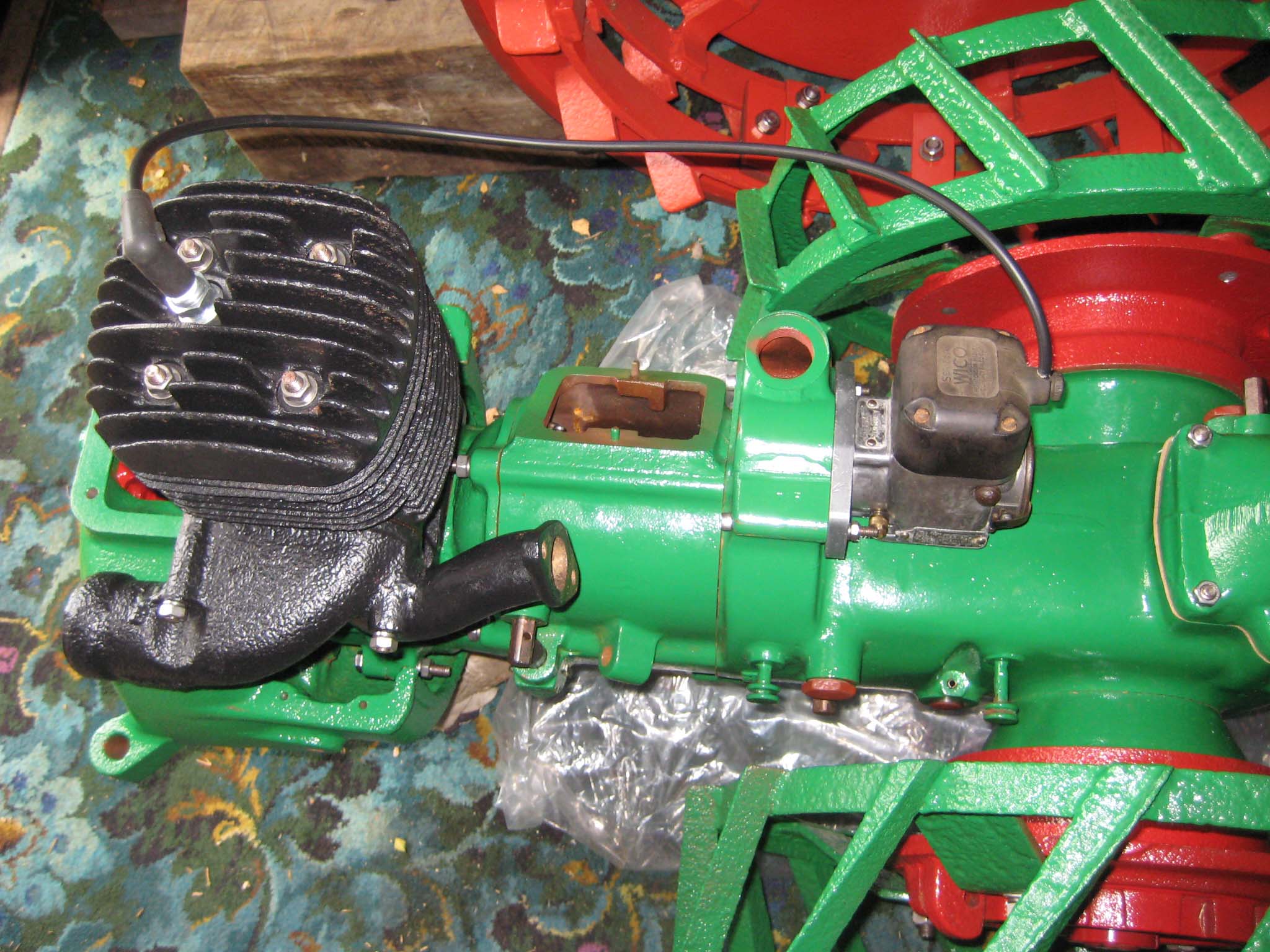
October 24, 2015 at 11:48 am #14980vhgmcbuddyKeymasterTo refit the magneto, I first needed to ensure that the piston was positioned at the point the magneto contact breaker would begin to open. I removed the cylinder head so I could use a dial test indicator to establish top dead centre (Simar 0092). I then marked the cooling fan adjacent to a lump on the right of the fan casing (Simar 0093). The fan was rotated anti-clockwise until the mark lined up with another lump on the fan casing (Simar 0094). The amount rotated was 68mm measured around the circumference of the fan. The reading on the dial test indicator showed that the piston had dropped by 6.8mm (Simar 0095), a factor of 10 less than the distance measured around the fan circumference. Coincidence or clever design?
I set the magneto up with the points just starting to open and then bolted it to the main gearbox (Simar 0096). The mounting plate on the magneto has slotted holes, so fine tuning of the timing can be done by slackening the bolts and rotating the magneto.Attachments:
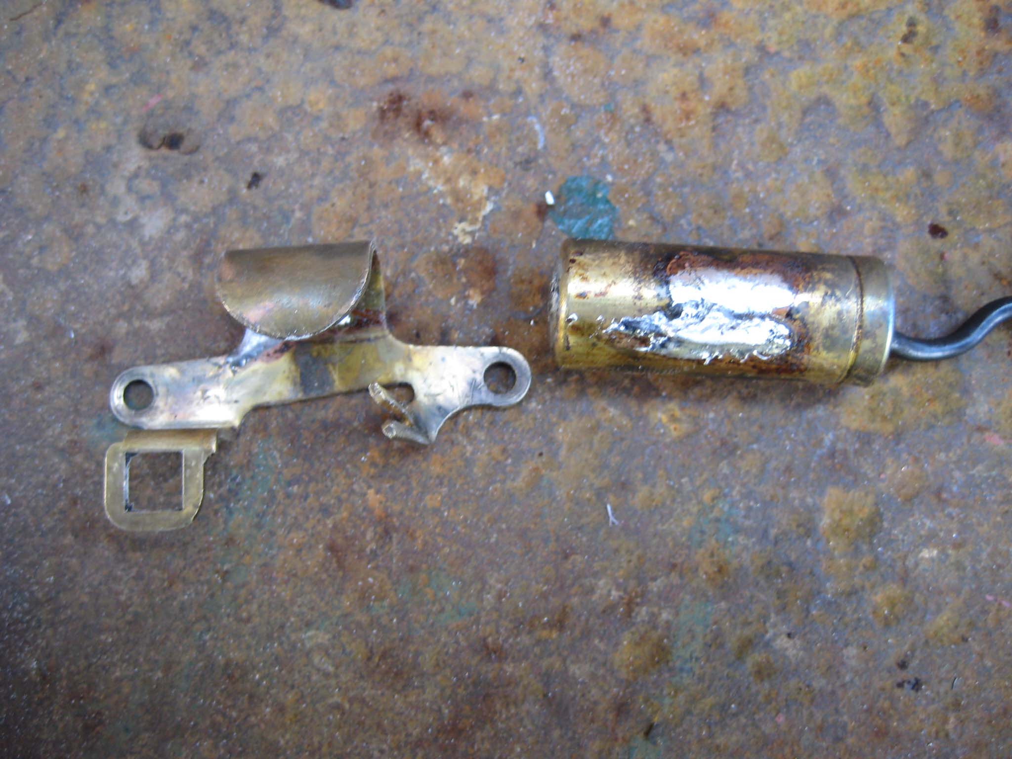
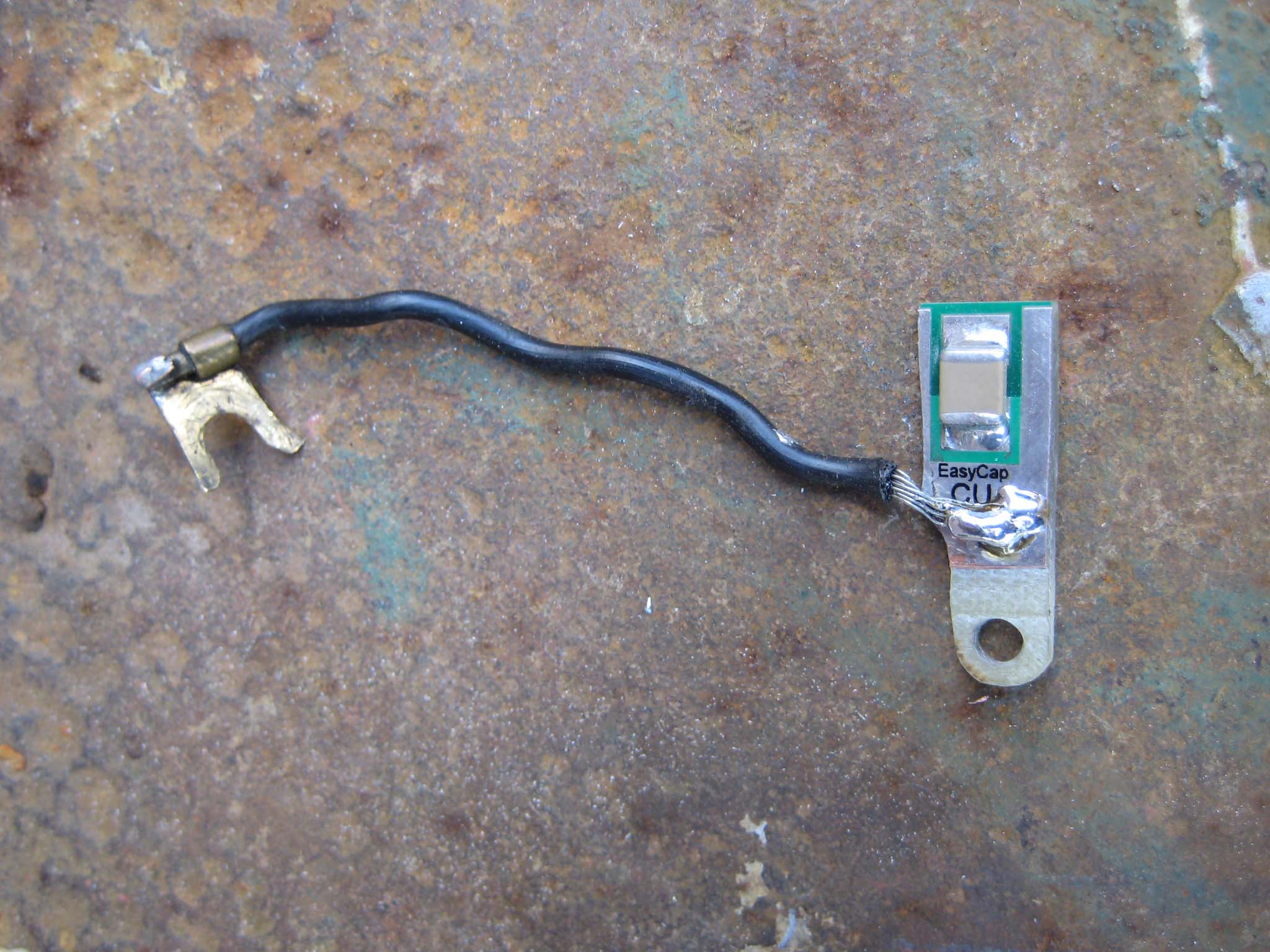
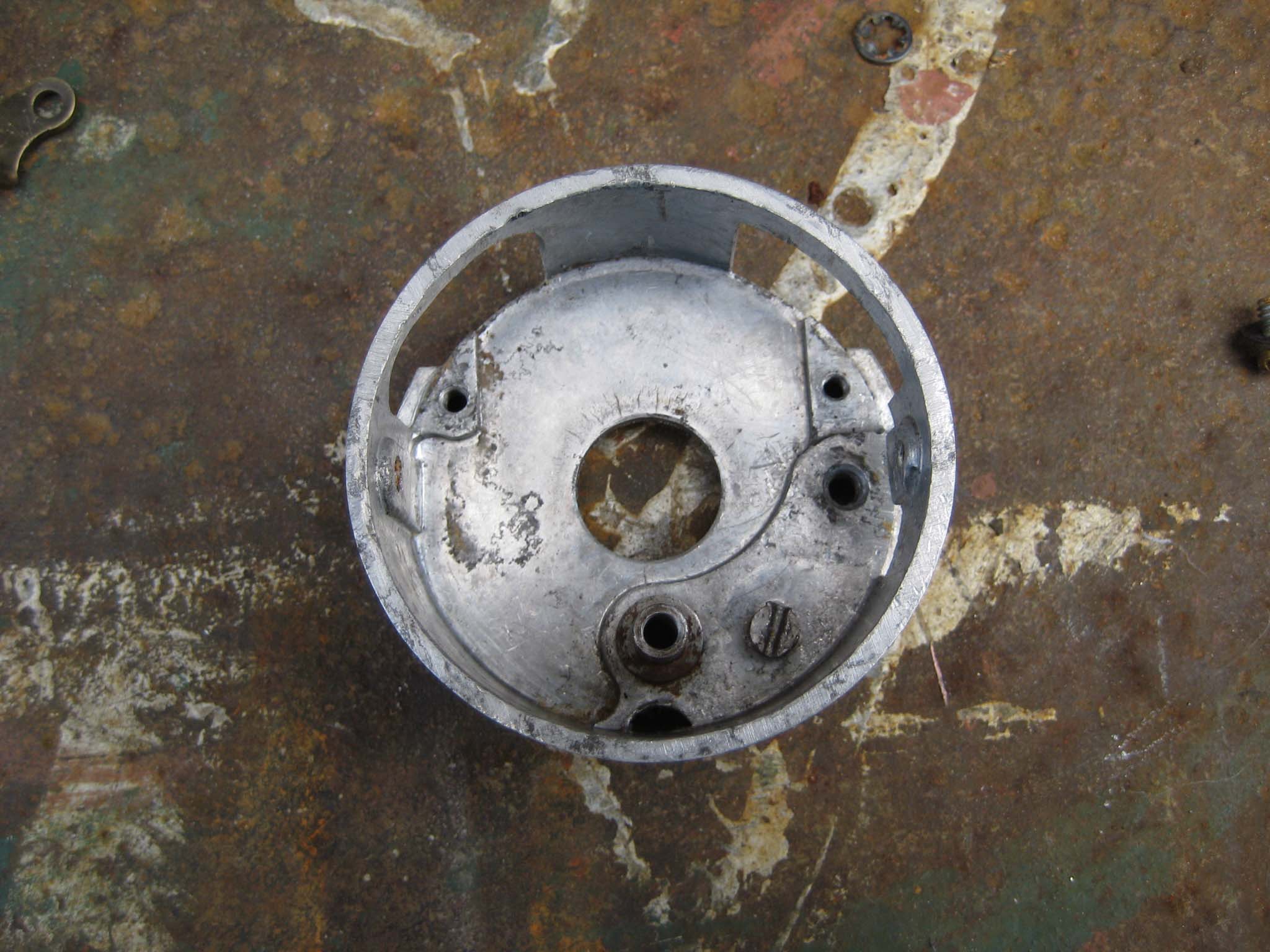
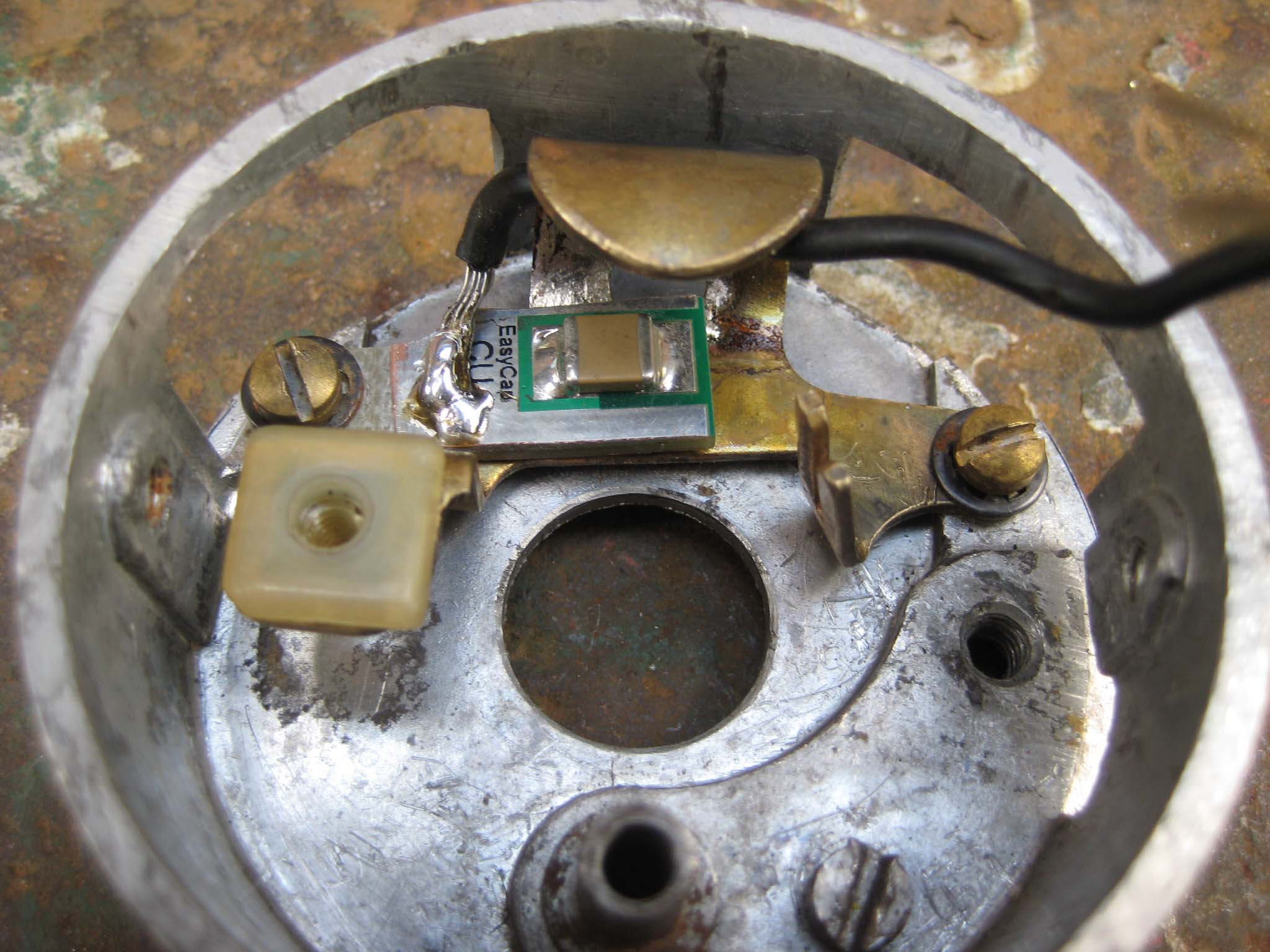
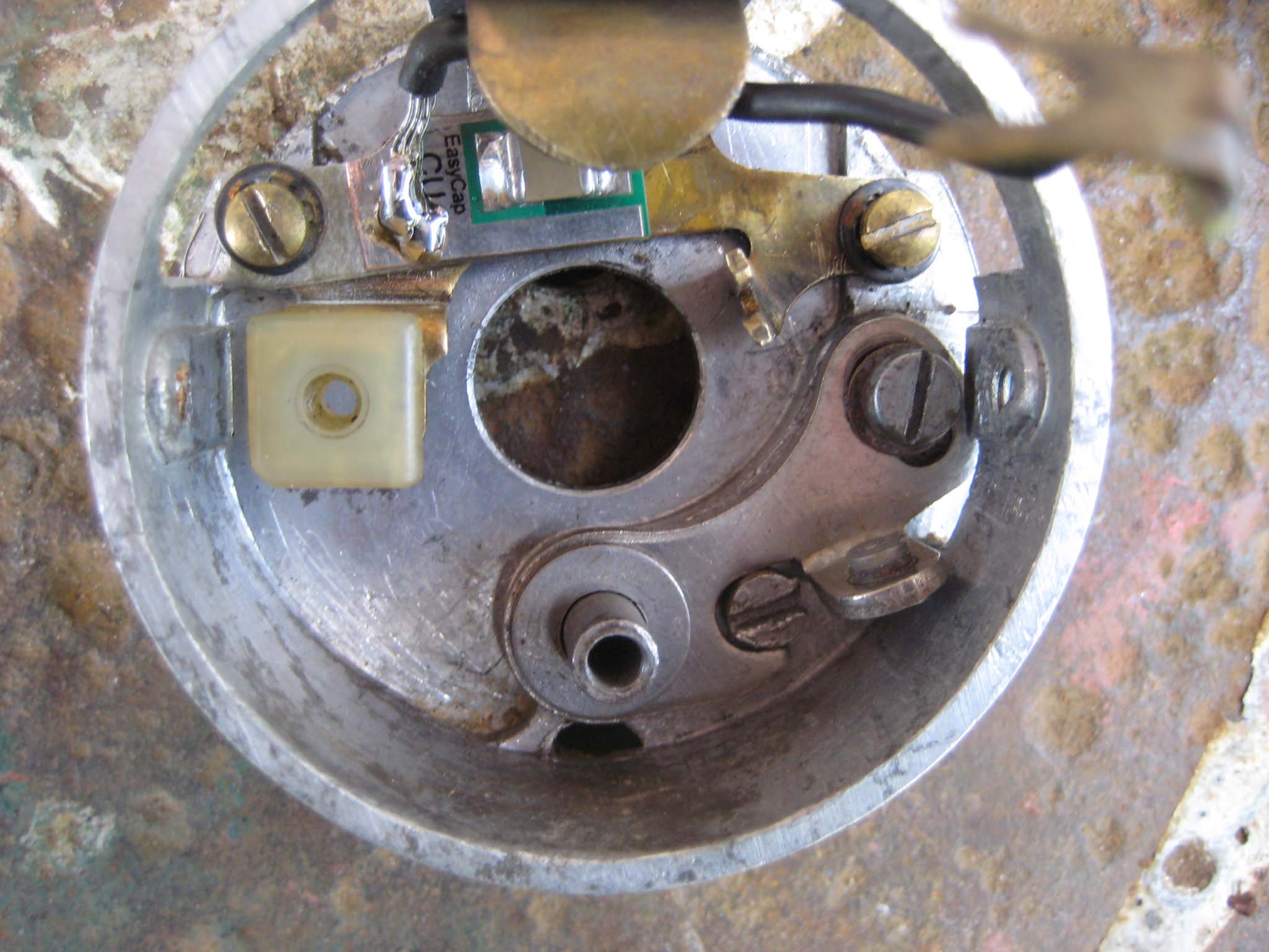
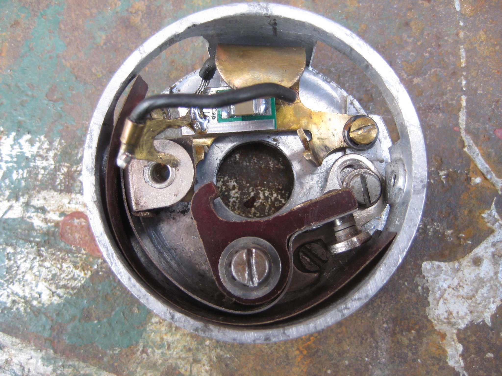
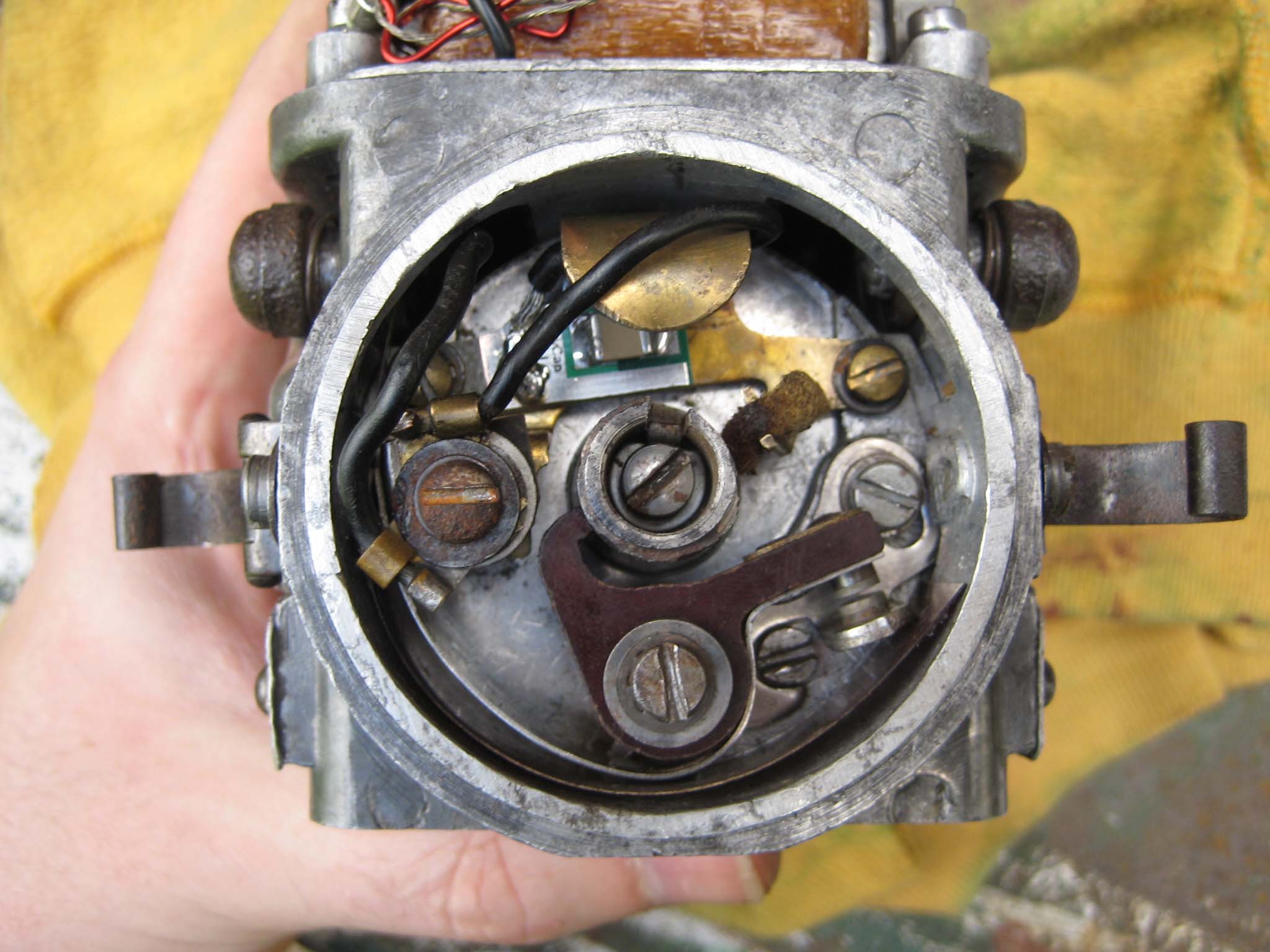
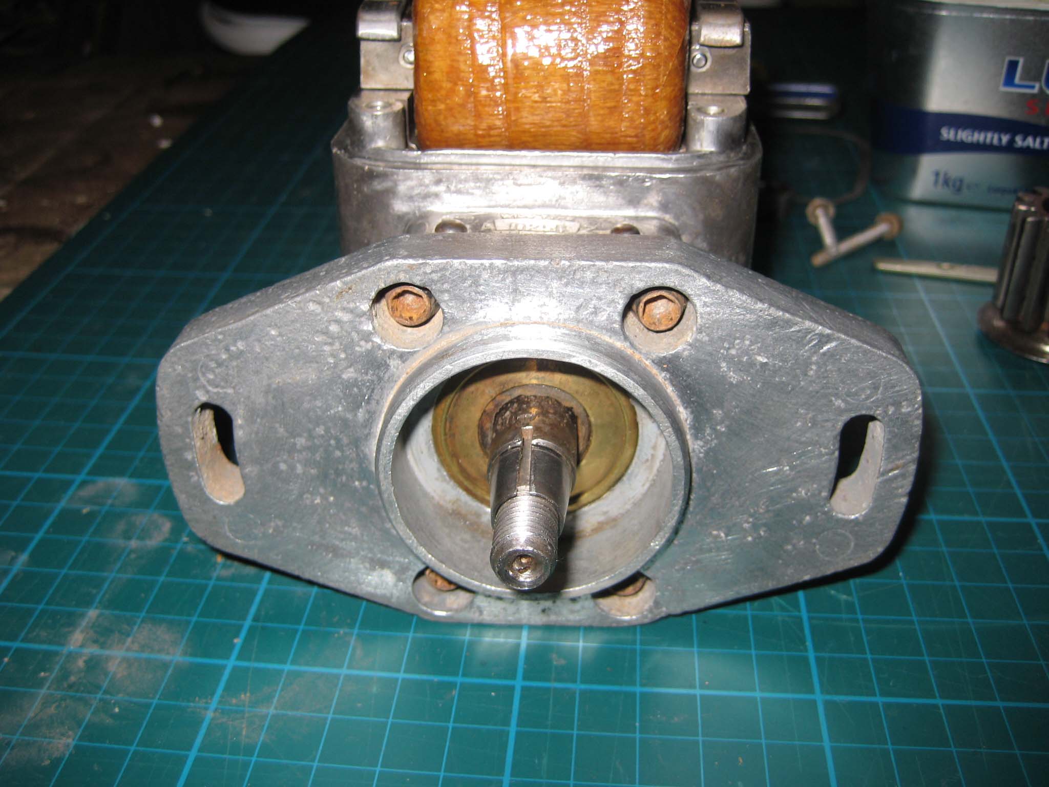
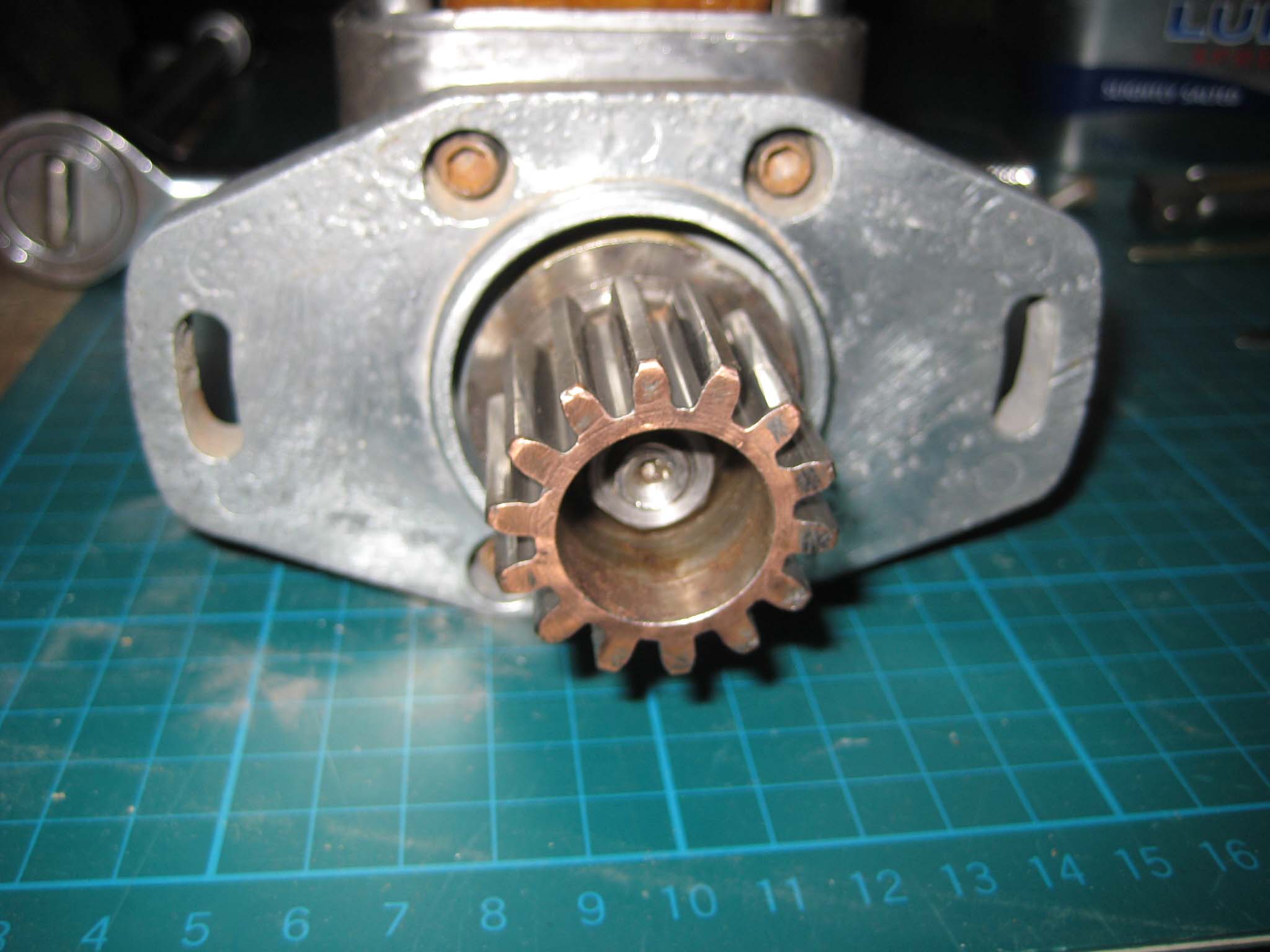
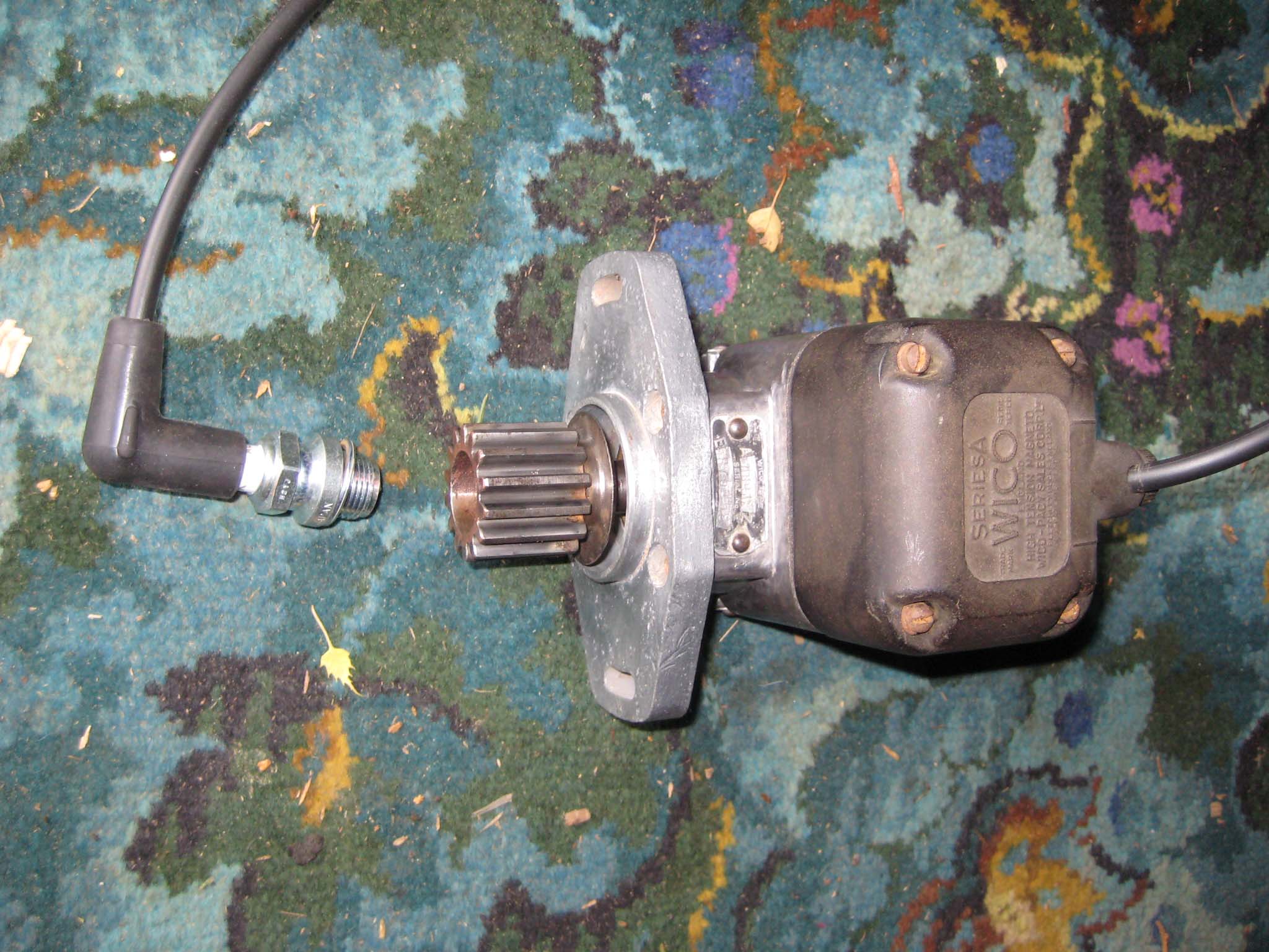
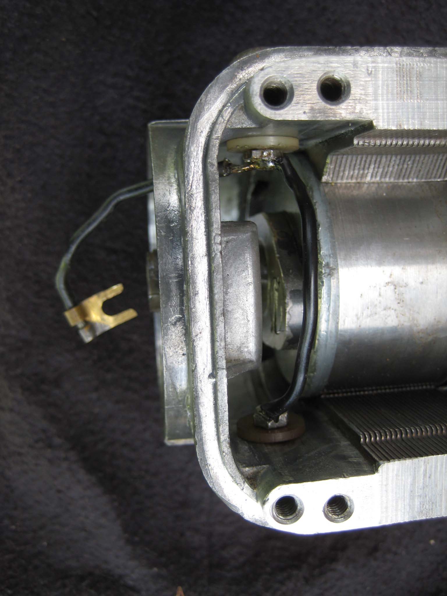
October 24, 2015 at 11:44 am #14969vhgmcbuddyKeymasterI had already decided that the original condenser would be replaced by an EasyCap condenser from Brightspark Magneto’s. To do this, the original condenser was unsoldered from it’s mounting bracket (Mag 0014). The EasyCap condenser was cut to size so that it would fit onto the condenser mounting bracket and the fly lead soldered in place (Mag 0015). The breaker box was cleaned (Mag 0016) and the condenser and mounting bracket fitted (Mag 0017). The fixed contact went in next (Mag 0018), followed by the breaker arm and strip of insulation around the inside lower half of the breaker box (Mag 0019). The breaker box was then slid back into the main housing, taking care not to trap any wires. The breaker box is clamped into place by the fixing screw which hold the front cover spring clips. The wiring was connected up to the condenser mounting bracket and the felt pad for the cam inserted into the fork in the condenser bracket (Mag 0020). The mounting flange complete with oil seal pressed into the centre was bolted to the main housing (Mag 0021). The drive gear fits on the rotor shaft tapered collar (Mag 0022). The gear is not keyed to the shaft. To complete the job, a new copper HT lead was fitted to the cover along with a NGK AB-6 spark plug (Mag 0023). End result is a fat, Blue spark, even at low speed.
Attachments:
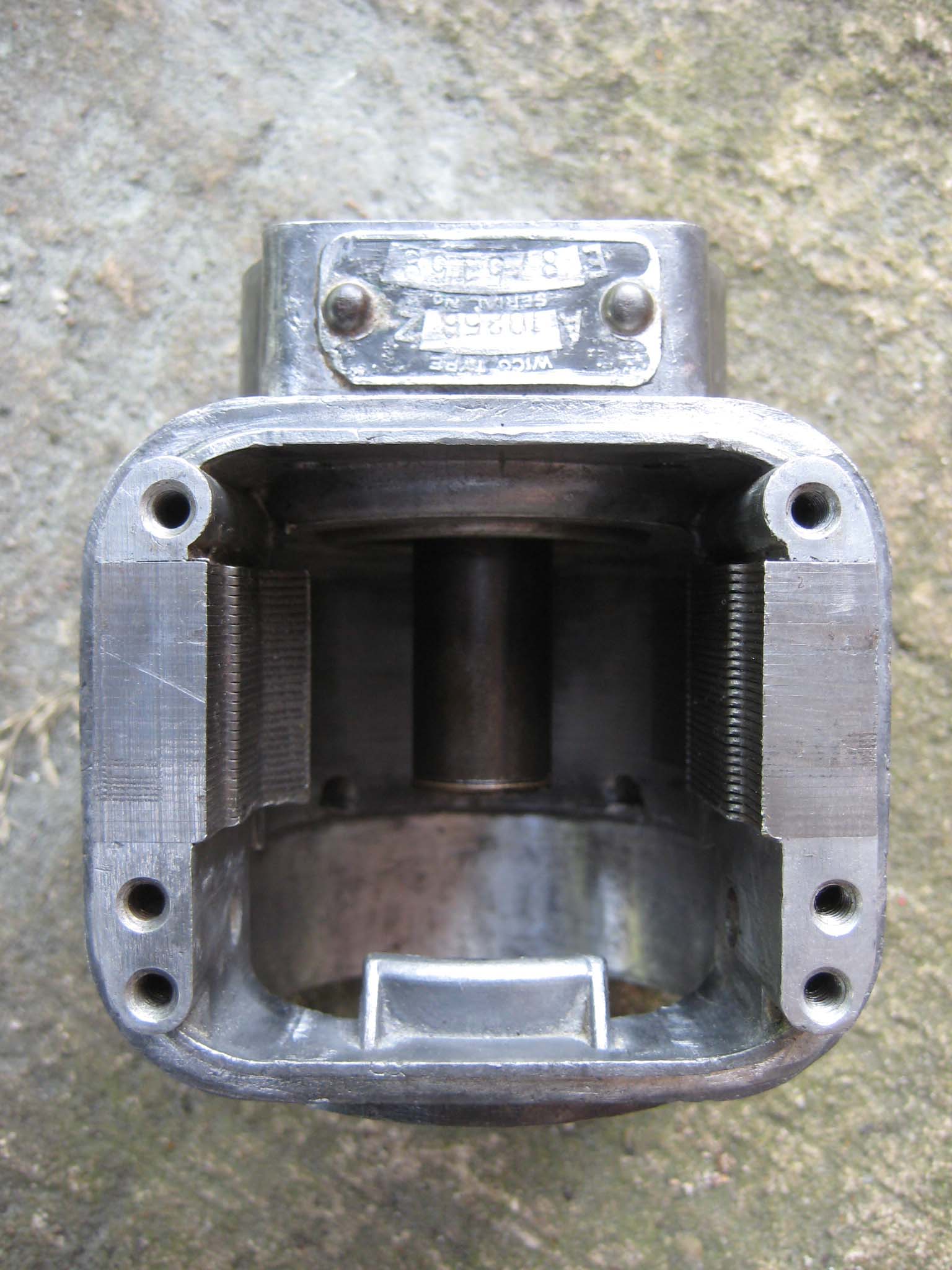
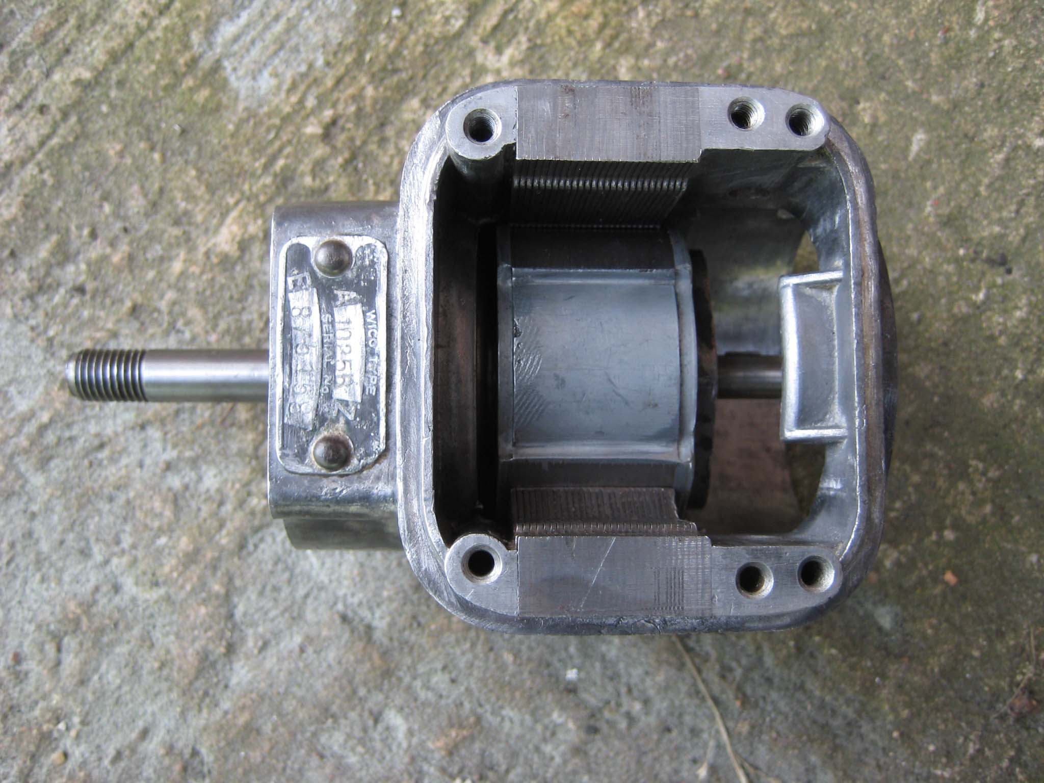
October 24, 2015 at 11:39 am #14955vhgmcbuddyKeymasterI now focused my attention on the magneto. My Simar 56a is fitted with a Wico Series A magneto, type A10258Z. I took the plunge and decided to treat it to a full strip down and refurbishment. The following details the rebuild.
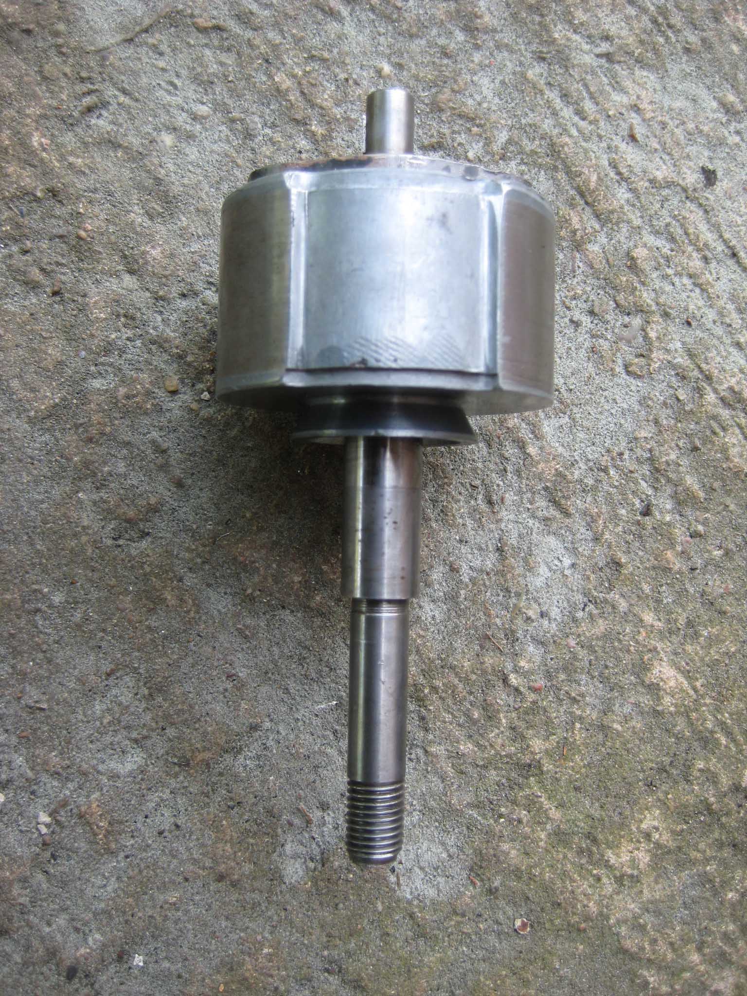
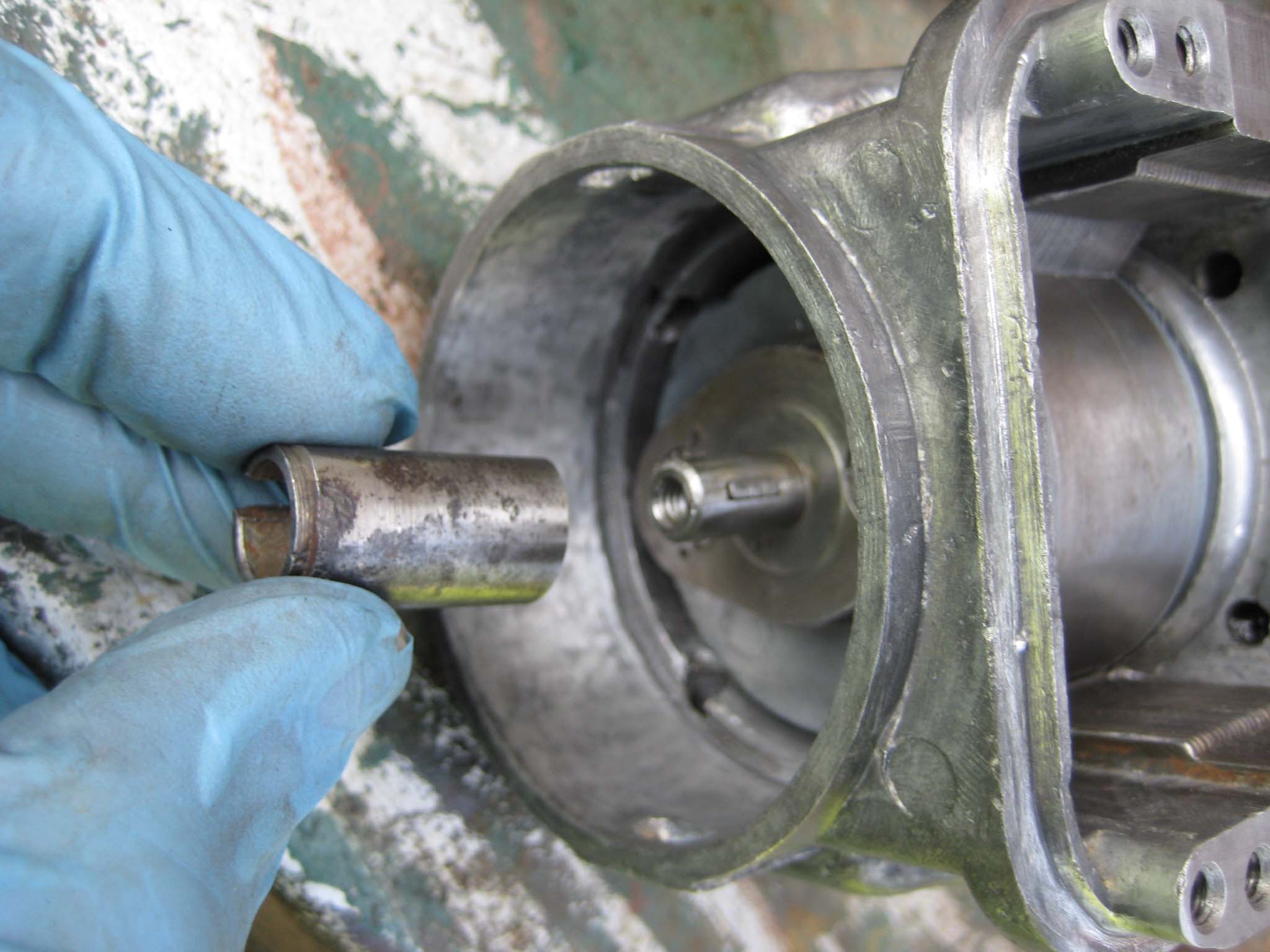
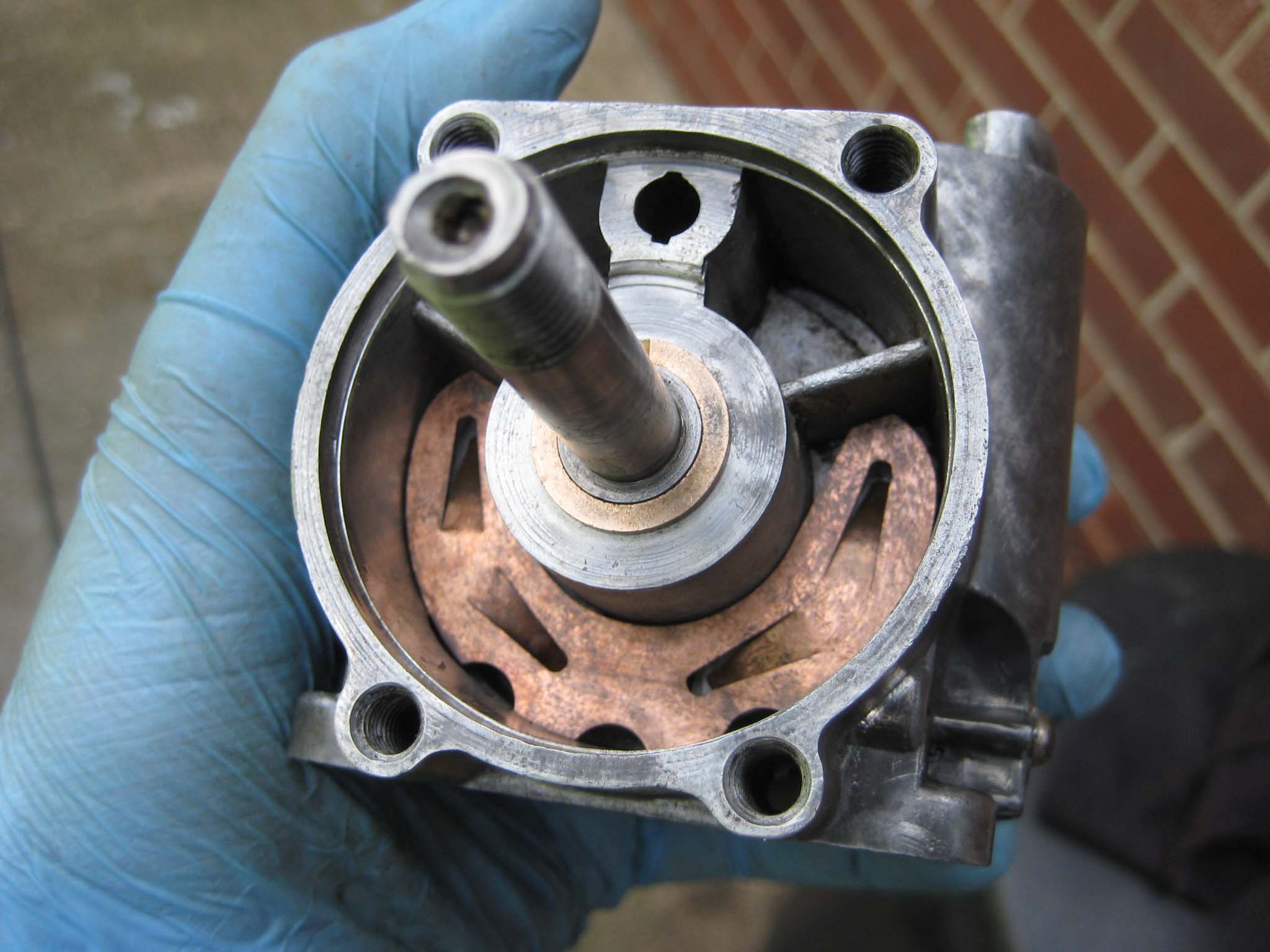
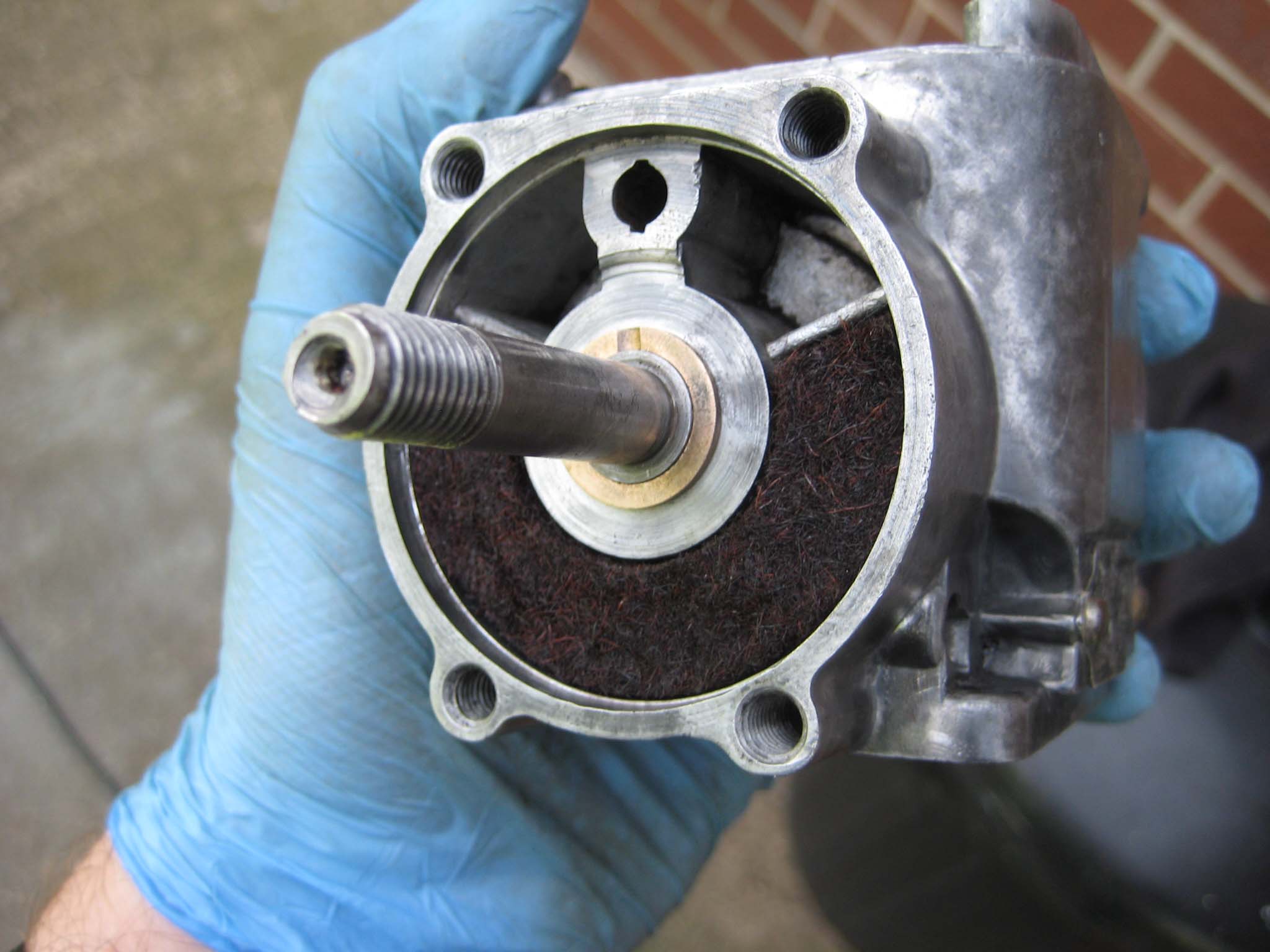
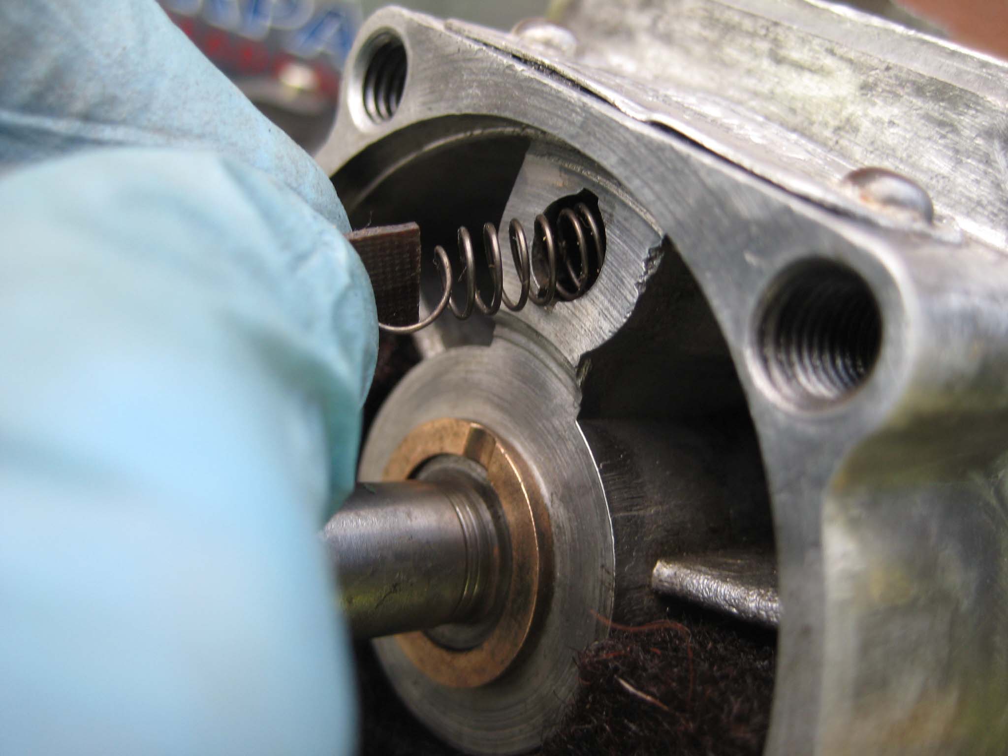
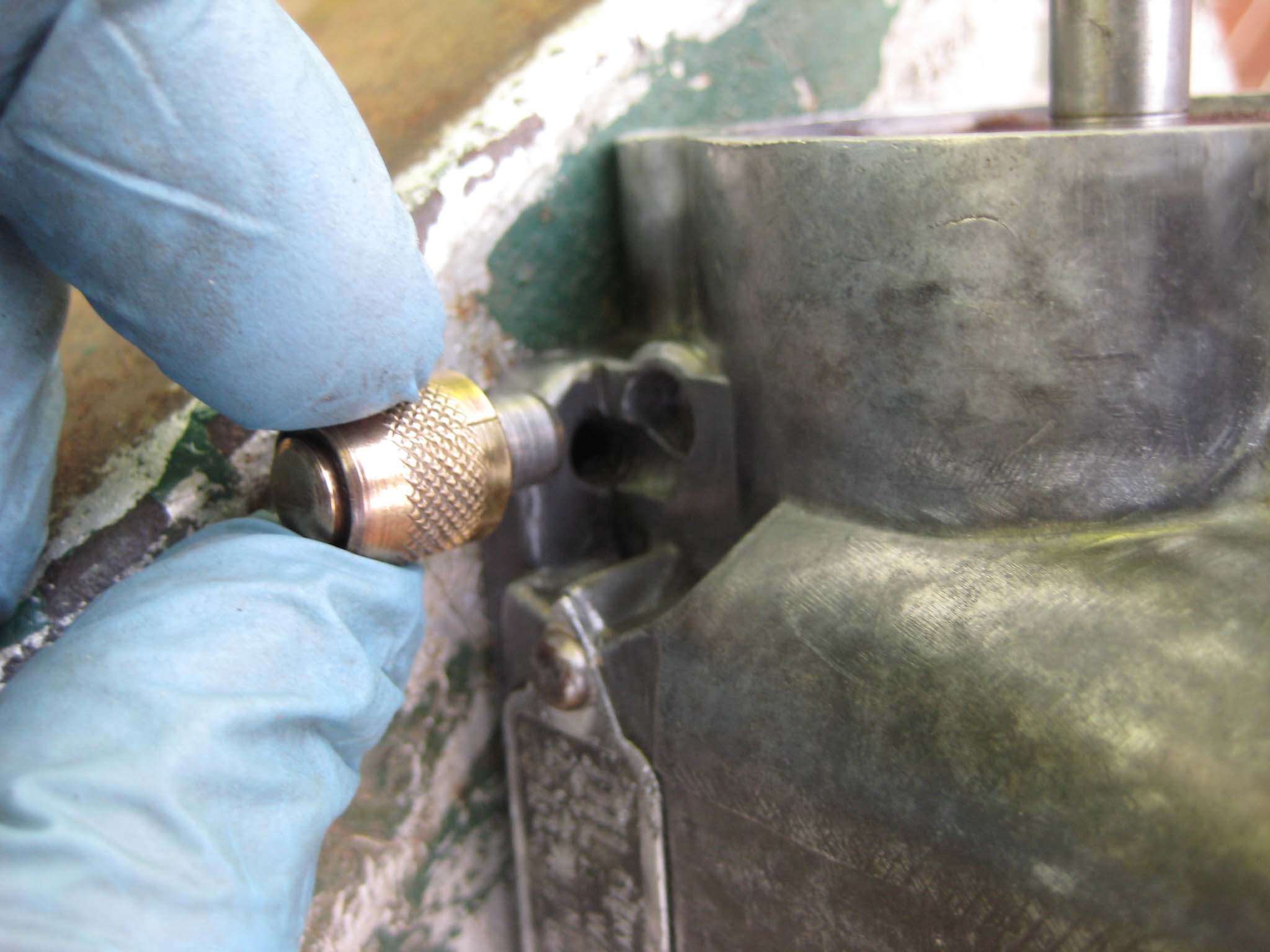
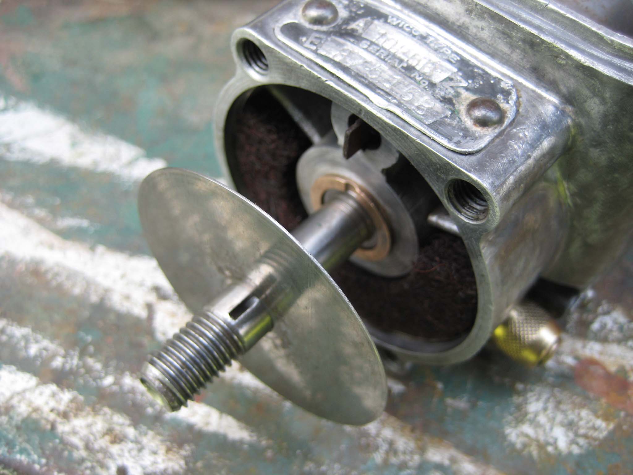
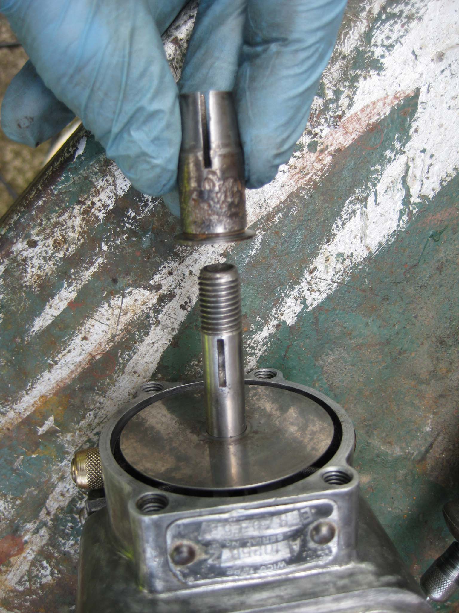
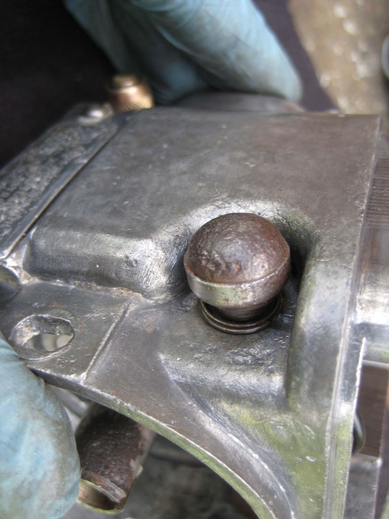
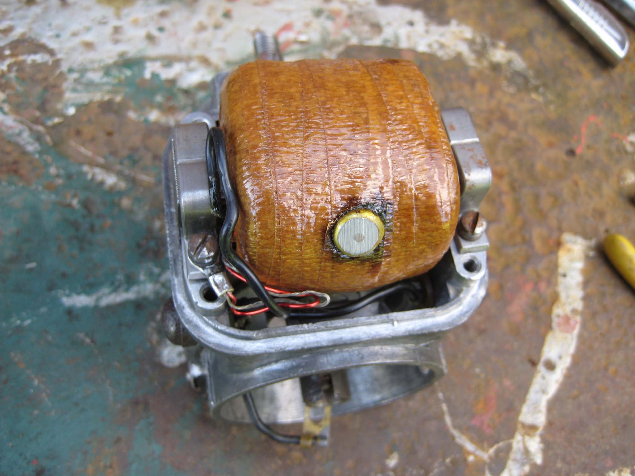
The main housing was cleaned (Mag 0001) in preparation for the rotor (Mag 0002). With the rotor back in the main housing (Mag 0003), the cam which operates the points was attached to the rotor via a half moon key (Mag 0004). The oil pad spring (Mag 0005), oil pad (Mag 0006) and sprung oil scraper assembly (Mag 0007) were fitted. The Brass oilers are a push fit into holes in the main housing (Mag 0008). To complete the lubrication system, the oiling disc was slid over the rotor shaft (Mag 0009). The Simar does not have an impulse coupling on the magneto to aid starting, instead having a tapered collar which is keyed to the rotor shaft (Mag 0010) onto which the drive gear will be installed later. The stop buttons (Mag 0011) were attached to the main housing, making sure not to forget the insulating washers that fit on the inside of the housing (Mag 0012). A new coil was fitted (Mag 0013) before moving on to the points.
Attachments:
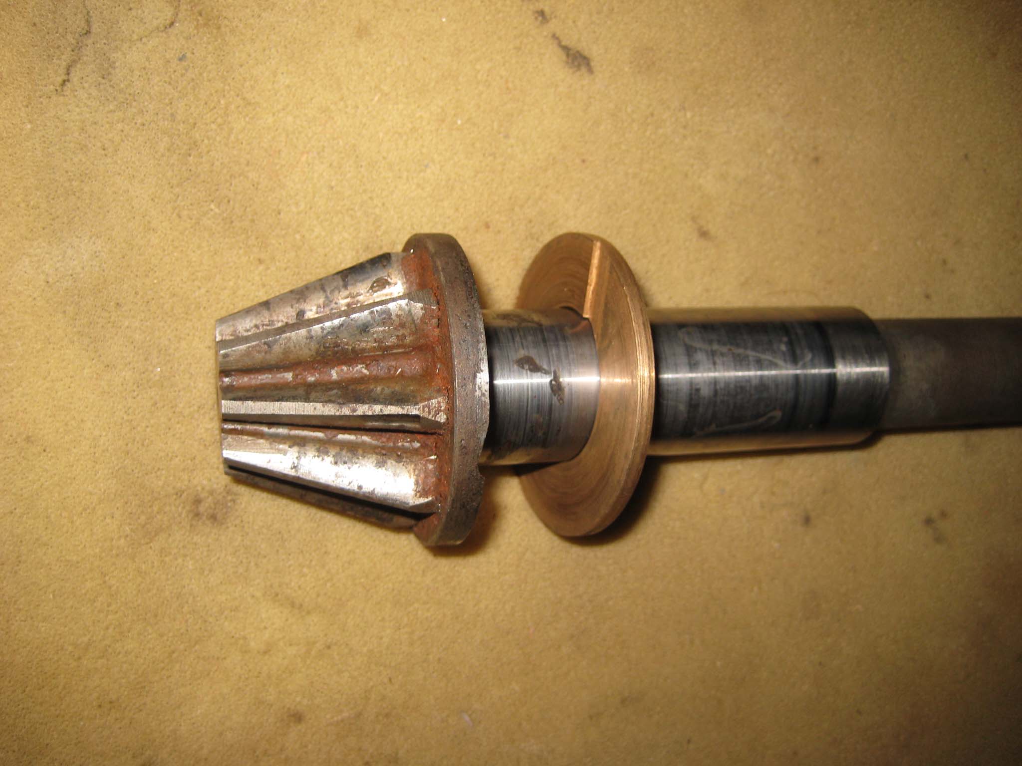
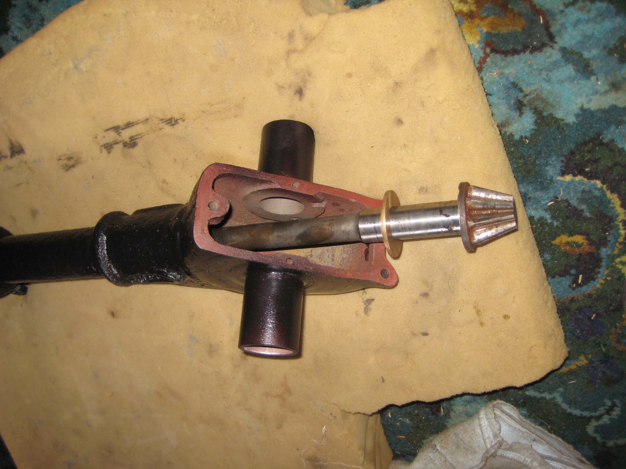
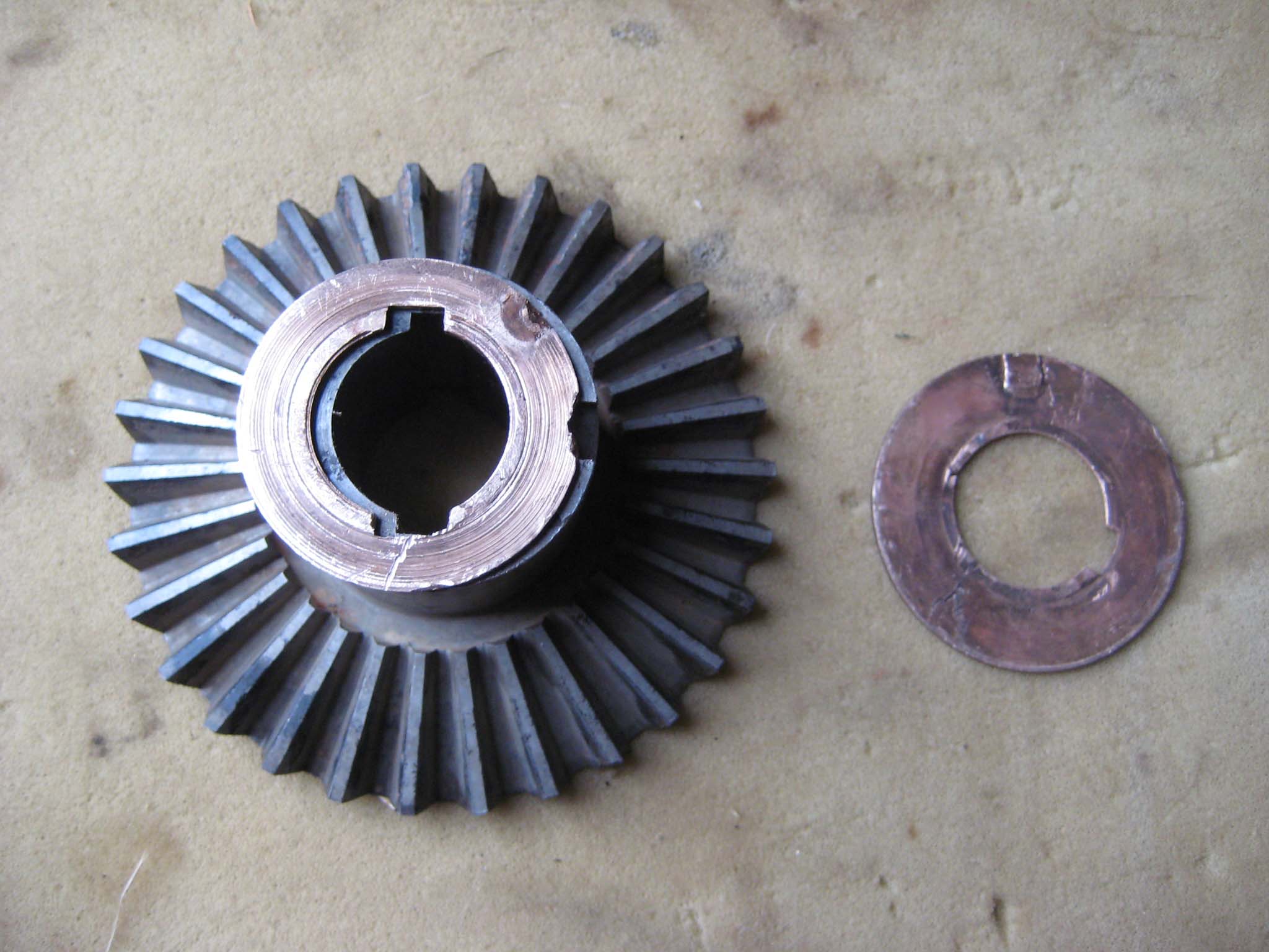
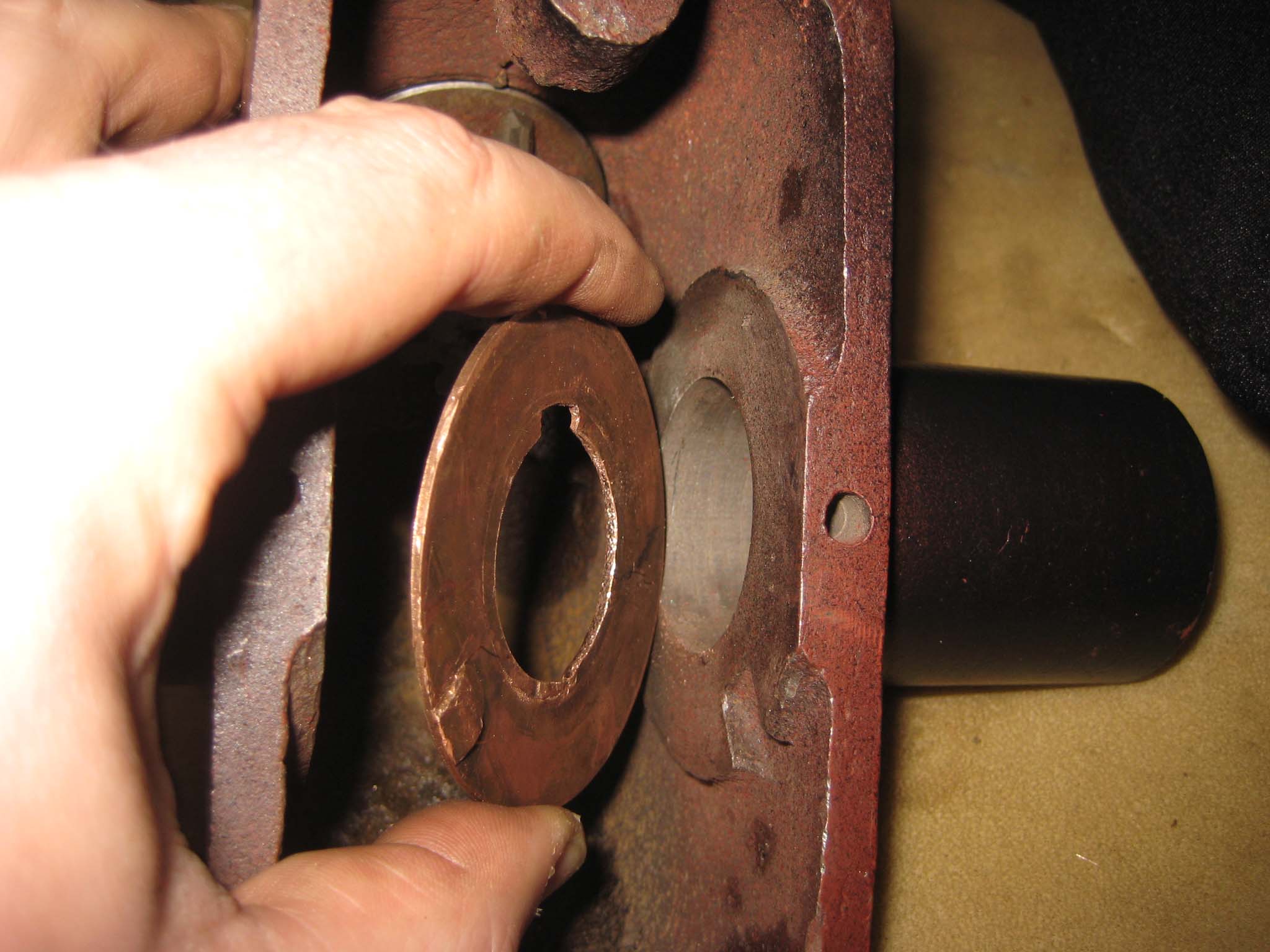
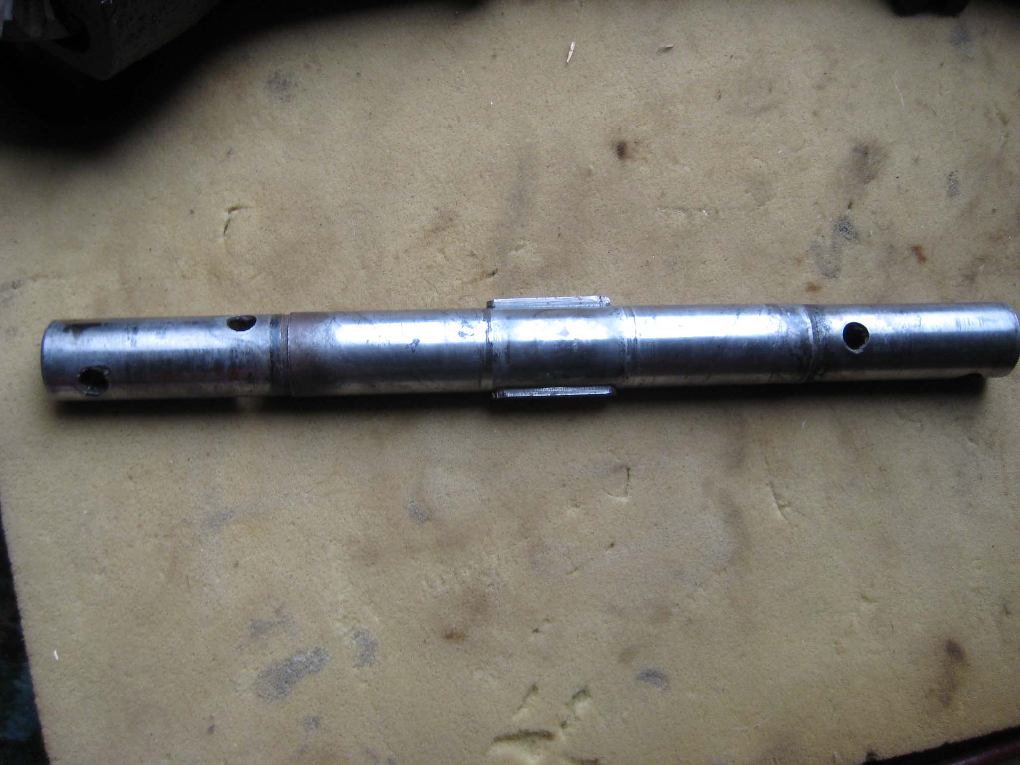
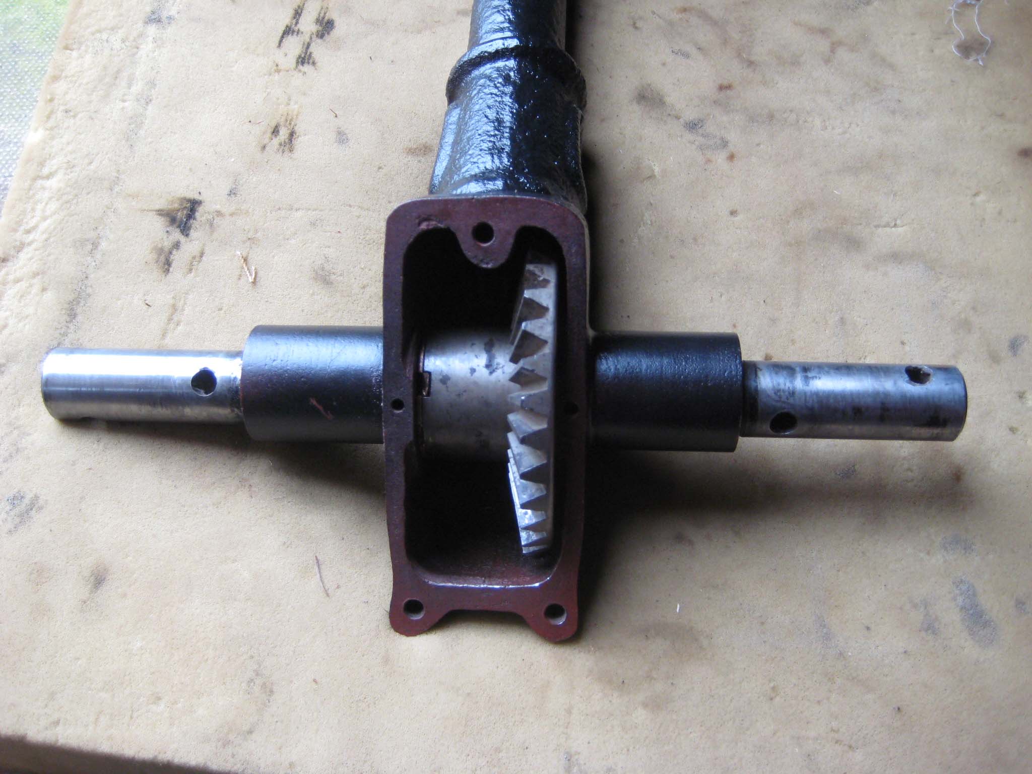
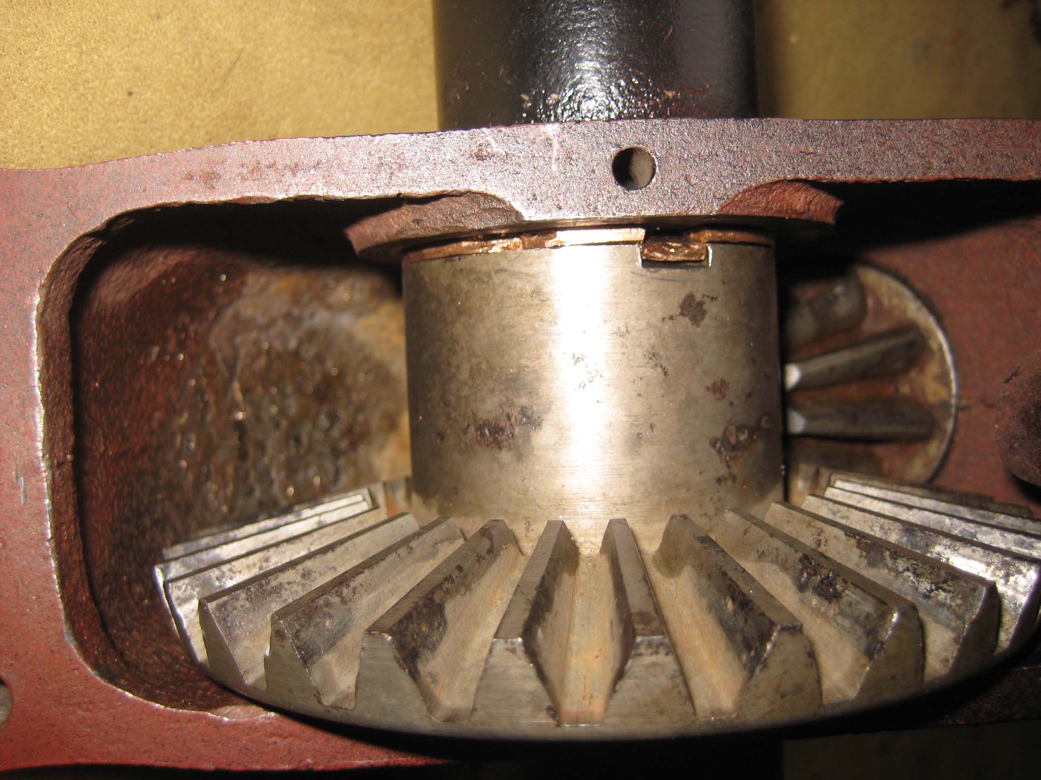
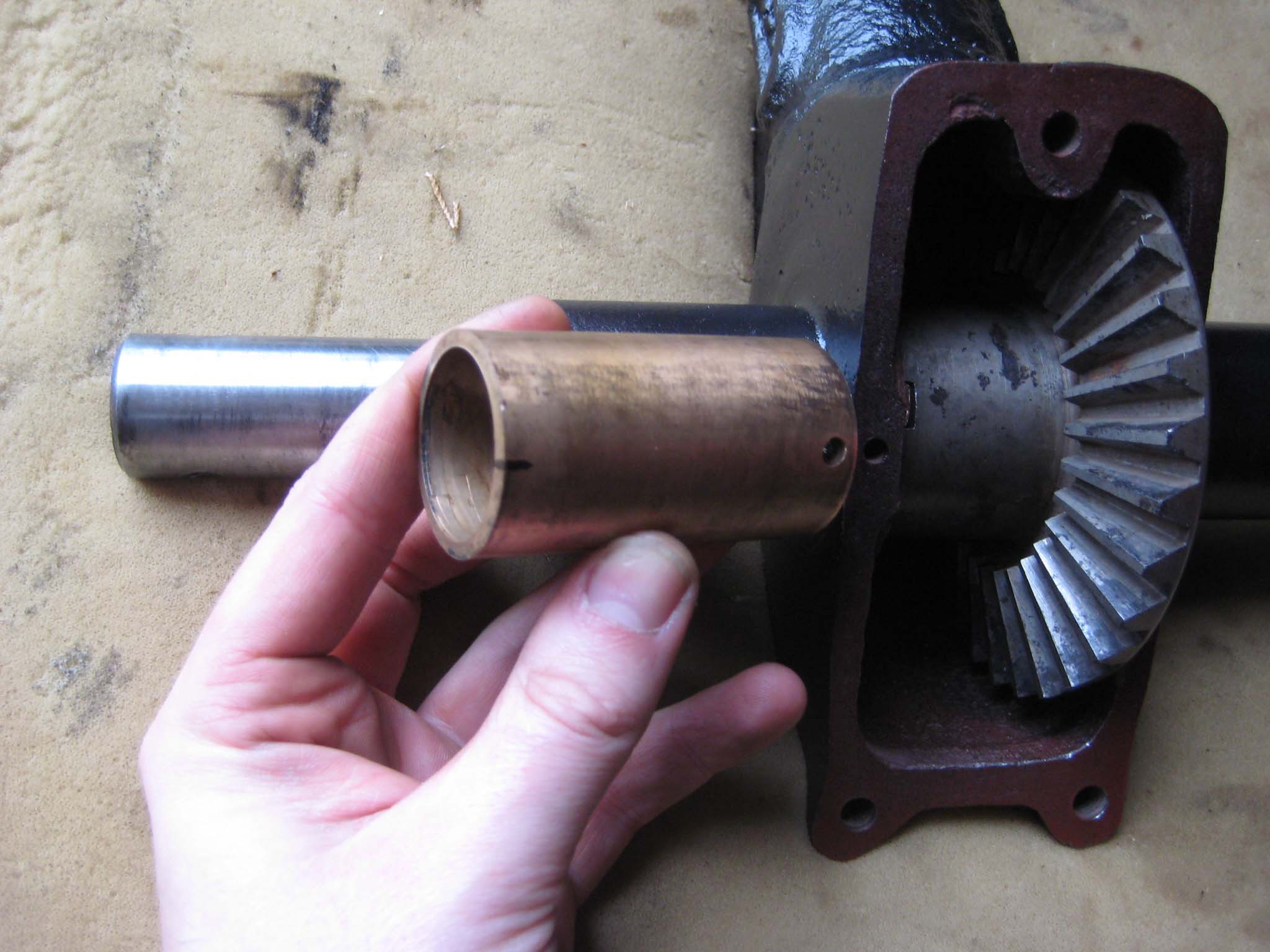
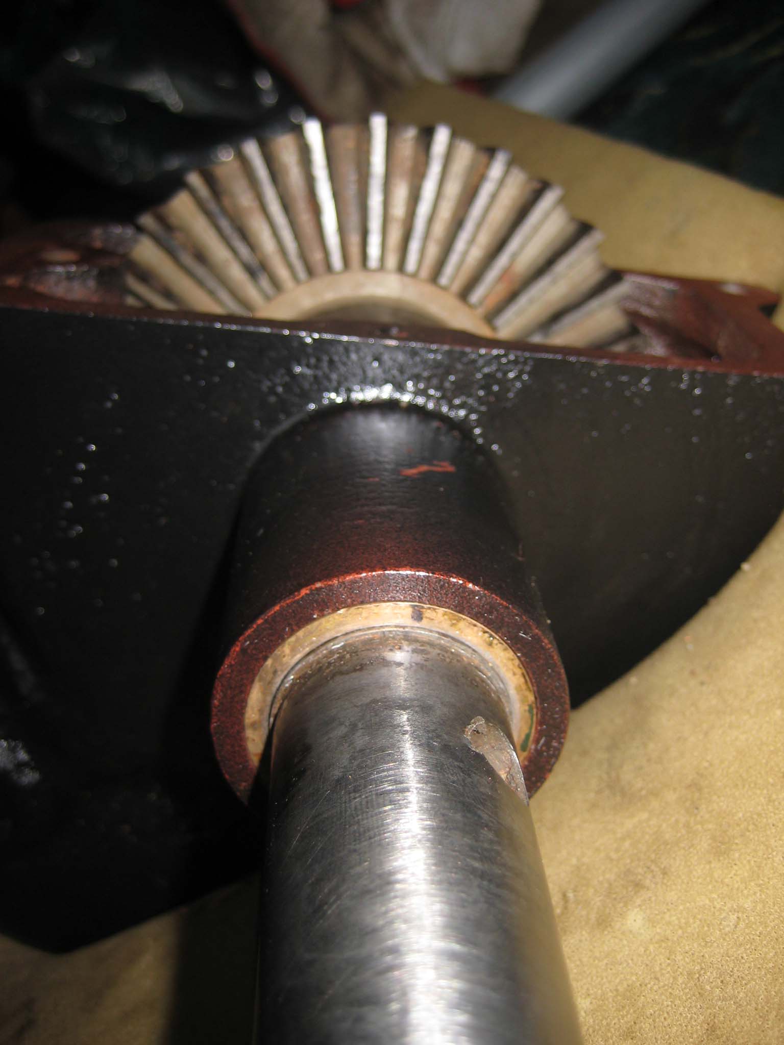
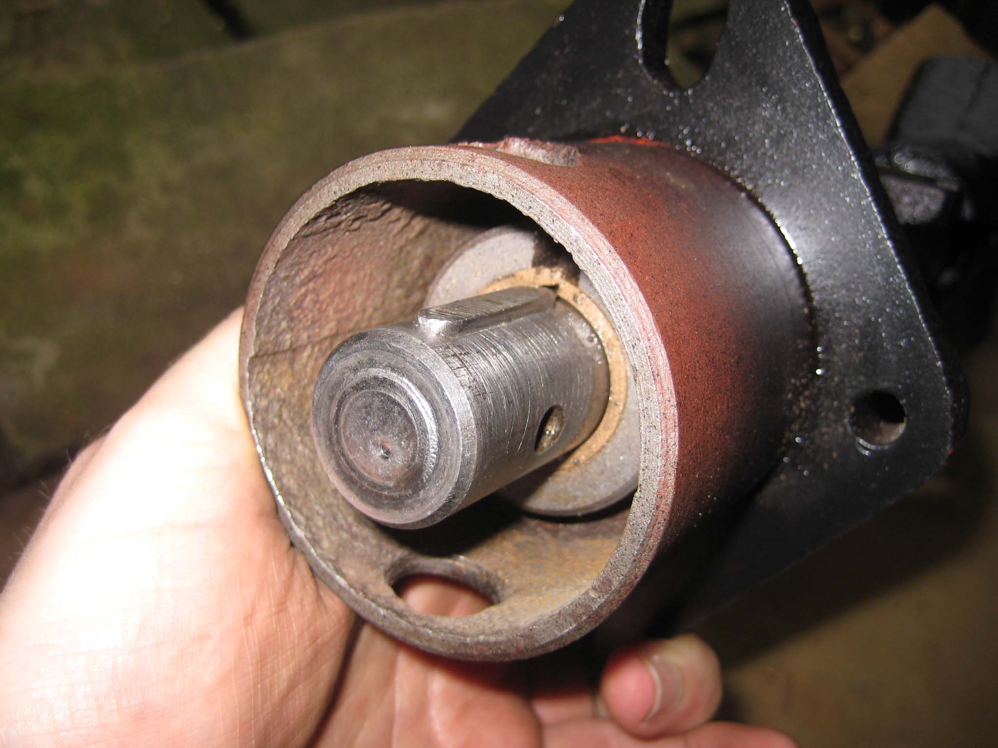
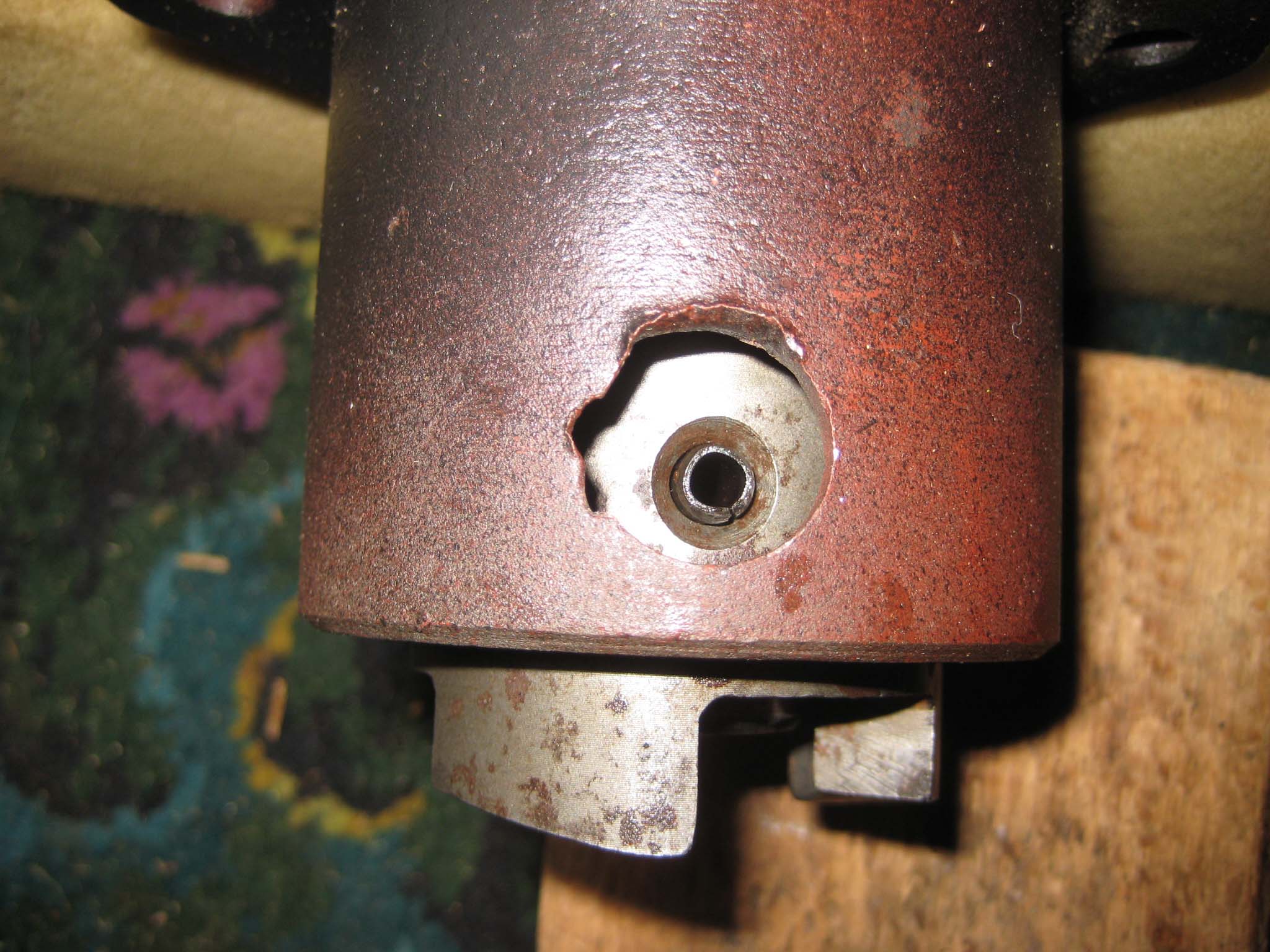
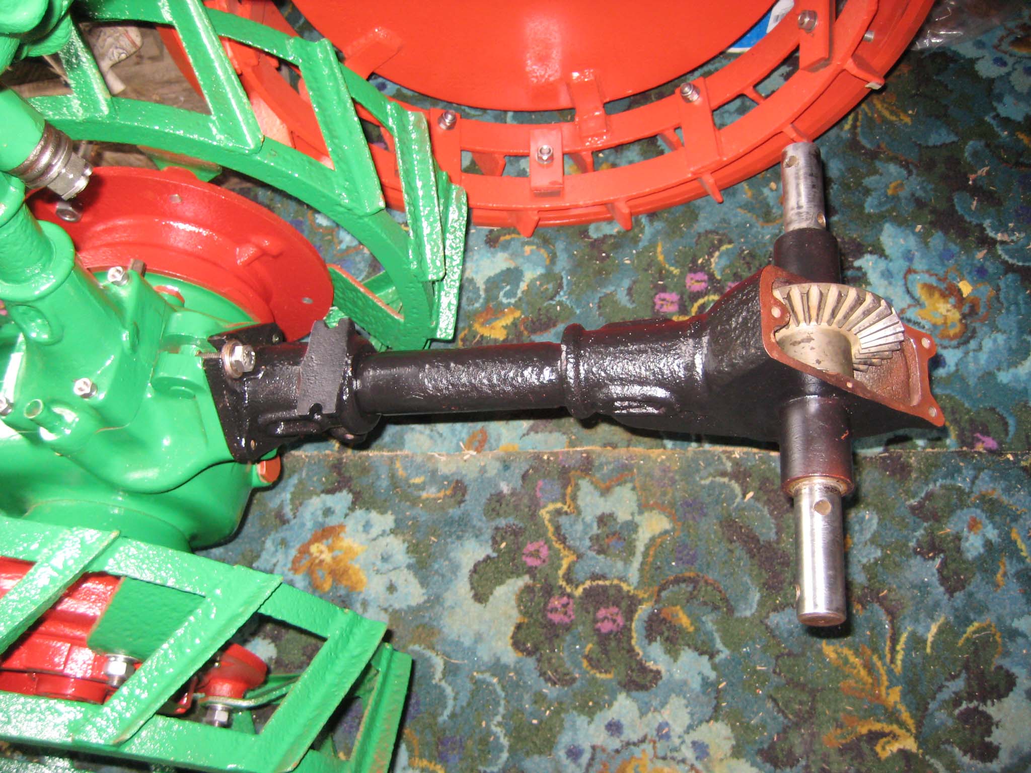
October 24, 2015 at 11:32 am #14942vhgmcbuddyKeymasterI next moved on to preparing the miller PTO assembly. The main drive shaft was fitted with a Steel thrust washer immediately behind the bevel pinion, followed by a Bronze thrust washer (Simar 0080). This was then fed through the Bronze bushes in the miller casing (Simar 0081). The crown wheel has thrust washers on either side. The left hand washer has cut outs in it to allow the keys on the miller cross shaft to pass through when the shaft is removed/installed. These are not visible when the unit is assembled, but there is a ‘V’ notch cut in the circumference of the washer which once lined up with a notch on the crown wheel indicates that the washer is correctly aligned for removal/installation of the cross shaft (Simar 0082). The right hand thrust washer includes a tab which sits in a notch on the inside of the miller casing, to ensure the washer does not spin against the casing wall (Simar 0083). Keys were fitted to the cross shaft (Simar 0084) and the shaft driven through the crown wheel from the left (Simar 0085). With the cross shaft in place, the left hand crown wheel thrust washer needs to be rotated by inserting a flat bladed screwdriver into the ‘V’ notch and gently tapping it around until the locking tab on the washer lines up with the notch in the crown wheel. Bend the tab over into the notch, so the washer will spin with the crown wheel (Simar 0086). The miller cross shaft bushes where then pressed into the casing. The bushes have a hole at one end which needs to align with a corresponding hole in the casing (Simar 0087 & 88). A pin will be installed later. The key was fitted to the driven end of the PTO shaft (Simar 0089) followed by the miller dog. The dog is held in place by a 6 x 50mm roll pin (Simar 0090). The miller PTO assembly was then bolted to the rear of the machine (Simar 0091).
Attachments:
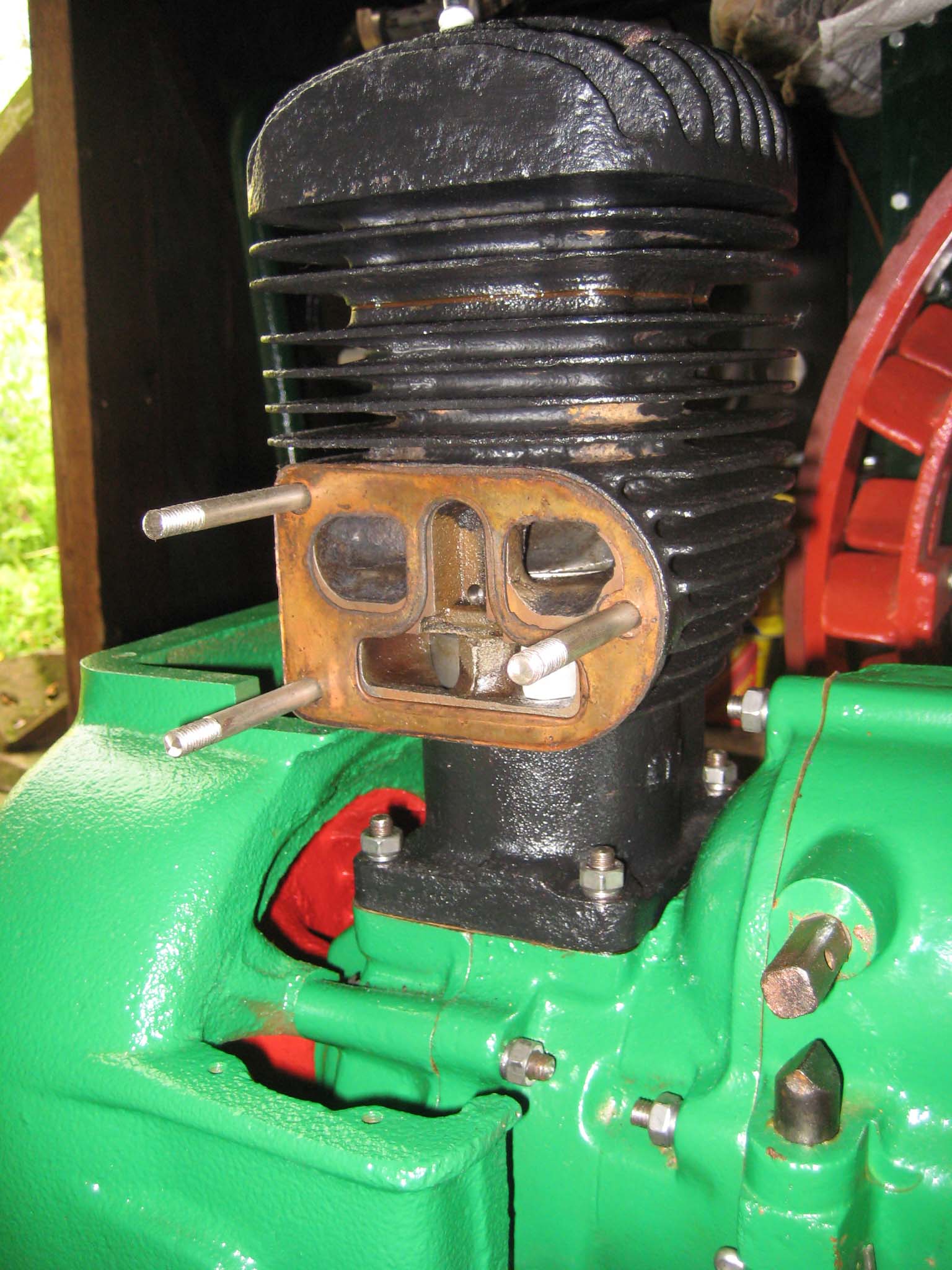
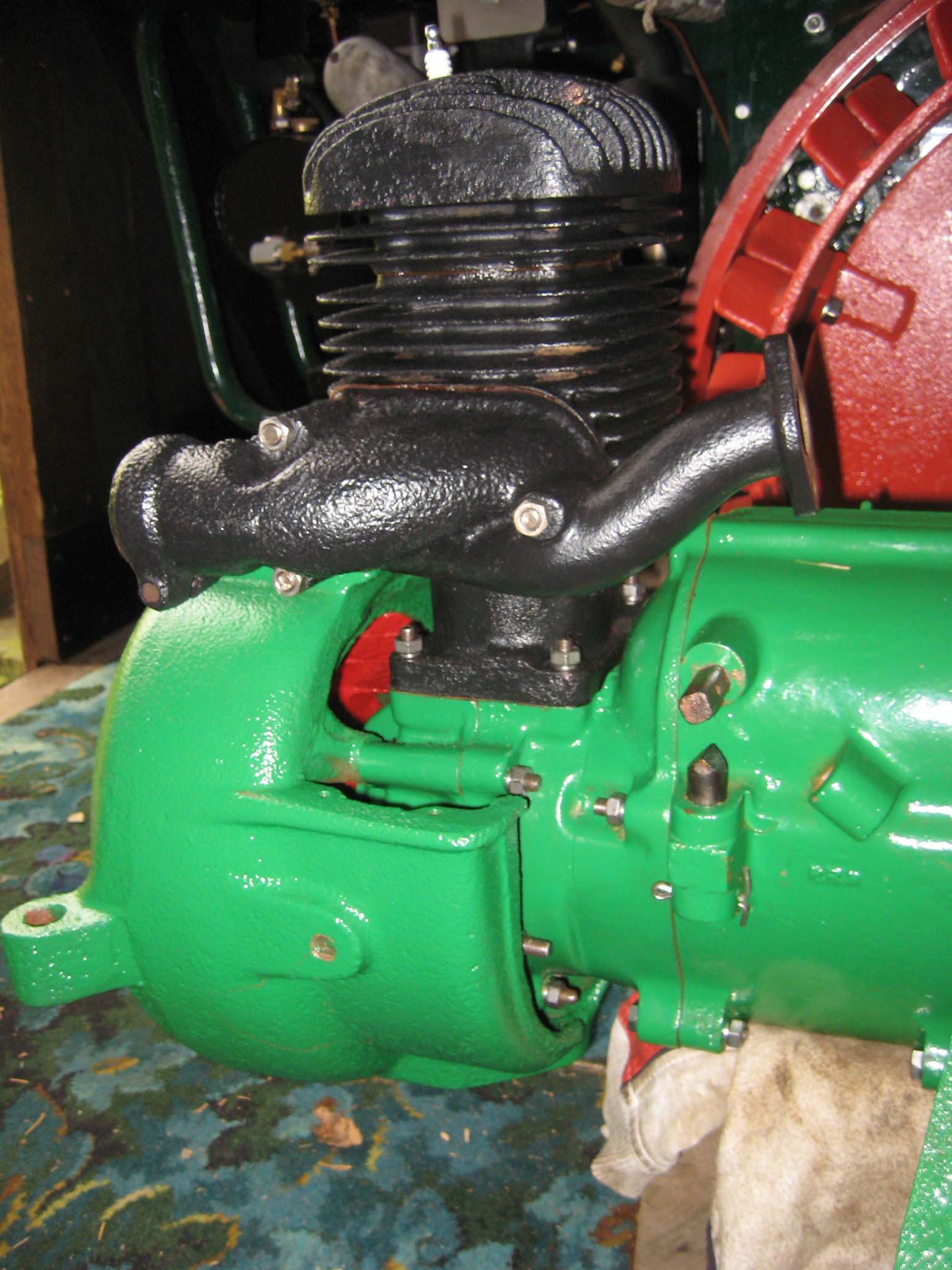
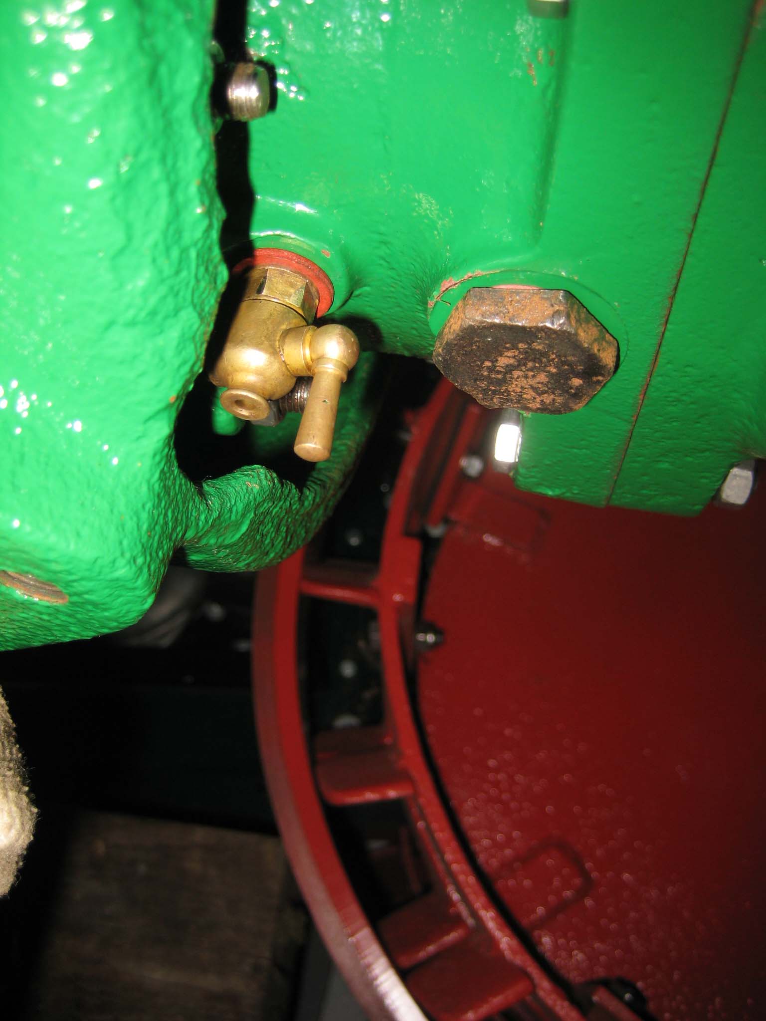
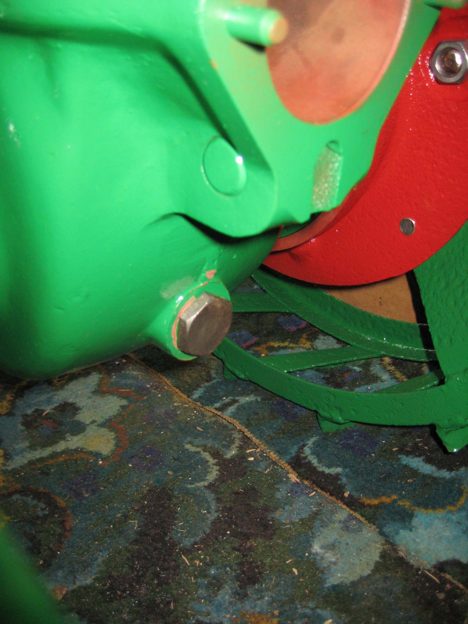
October 24, 2015 at 11:26 am #14937vhgmcbuddyKeymasterThree M8 studs were fitted into the cylinder barrel, along with the copper exhaust/air intake manifold gasket (Simar 0076), followed by the manifold (Simar 0077). The crankcase drain tap was re-fitted, along with the gearbox oil drain plug (Simar 0078). The tap would have been much easier to fit before the fan casing had been installed. There is another drain plug at the rear of the main gearbox (Simar 0079).
Attachments:
October 23, 2015 at 12:41 pm #14920vhgmcbuddyKeymasterHi Joe
Thanks for the information very much appreciated
Richard
October 22, 2015 at 6:17 pm #14907vhgmcbuddyKeymasterTractor looking great Alan !!
October 22, 2015 at 6:15 pm #14906vhgmcbuddyKeymasterJust emailed you short articles and photos on a couple of events for the December Cultivator Mr Editor sir !!
October 21, 2015 at 12:51 pm #14892vhgmcbuddyKeymasterTry again
Attachments:
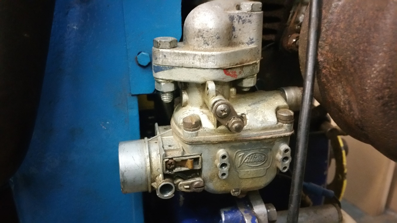
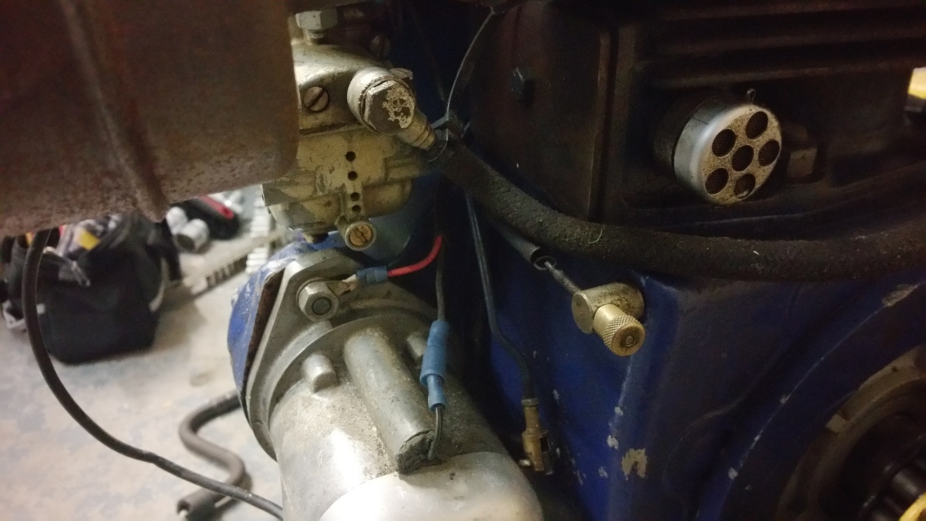
October 21, 2015 at 12:39 pm #14891vhgmcbuddyKeymasterHere are a couple of pics of the carb, I have checked the jets are clear on the carb but it looks like something is missing from the front of it.
So my question is can the missing bits be obtained or would it be easier to replace the carb?
October 19, 2015 at 10:42 pm #14888vhgmcbuddyKeymasterStrange no offers of help? All lawn mower collectors must be off line!
Your machine would be made by Atco between 1936 and 1938
If you are going to strip that clutch watch out for the springs, don’t loose them!October 19, 2015 at 4:32 pm #14882vhgmcbuddyKeymasterTry eBay, you can buy A4 size sheets.
-
AuthorPosts