
Forum Replies Created
-
AuthorPosts
-
November 10, 2016 at 8:55 pm #22988vhgmcbuddyKeymaster
I’m away from home till next week but I will check out the engine number and post a couple of pictures then
November 9, 2016 at 11:38 pm #22974vhgmcbuddyKeymasterI would kill for a shed like that Charlie
I could get all my Bolens in there!
November 9, 2016 at 11:31 pm #22972vhgmcbuddyKeymasterSounds like she needs an over haul 😉
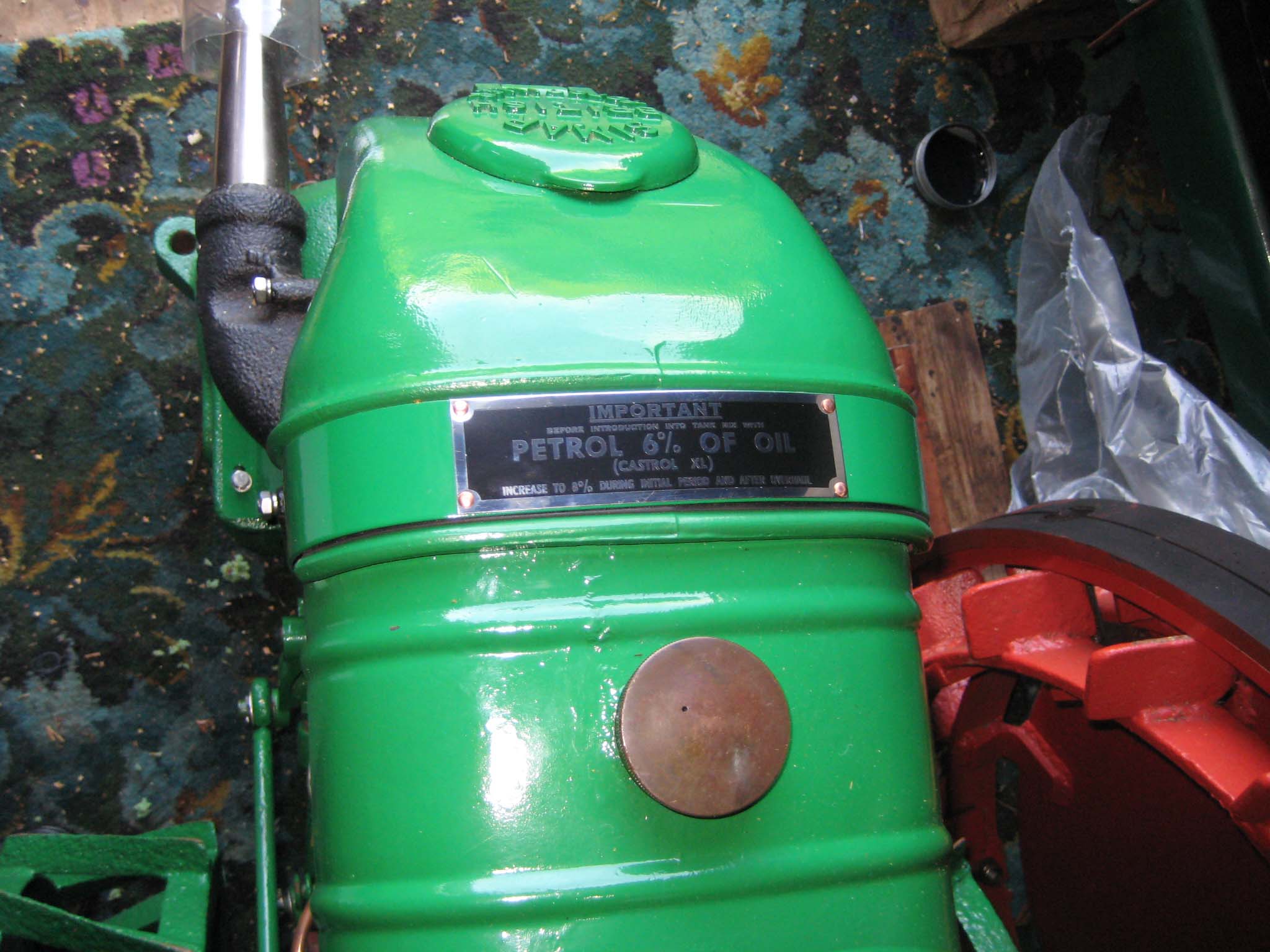
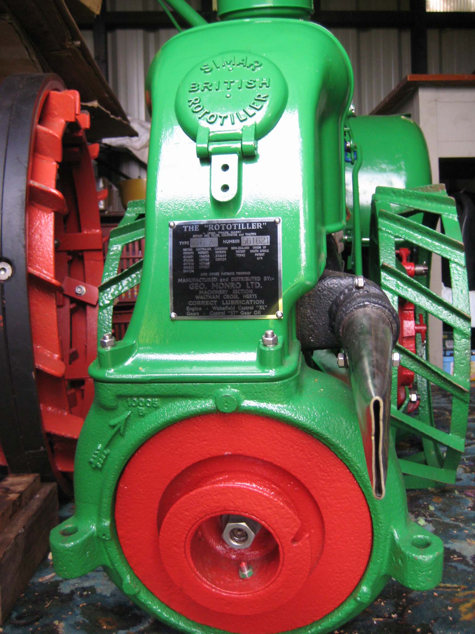
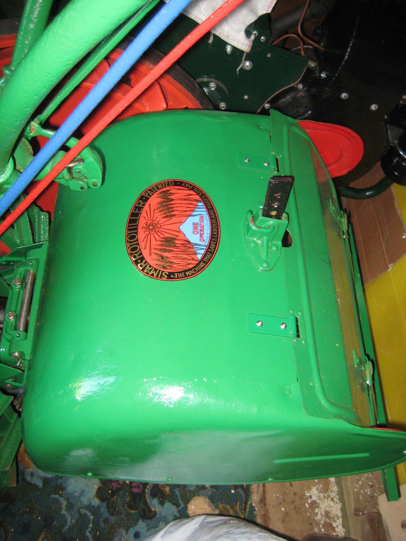
November 9, 2016 at 7:53 pm #22964vhgmcbuddyKeymasterThe original identification plates were damaged, so they were used as templates by Vintage Brass Plates to produce replacements. The fuel mixture plate is riveted to the front fuel tank strap (Simar 0147). I used 2mm diameter copper rivets intended for model steam locomotives, which were peened over with a hammer on the back face of the strap. The main identification plate is fixed to the engine cowl by No. 6 x 1/4″ long pan head hammer drive screws (Simar 0148). A decal for the miller cover was supplied by Charlie Moore (Simar 0149). The only outstanding parts left to fit are the wooden balls which fit into the ends of the handlebar tubes.
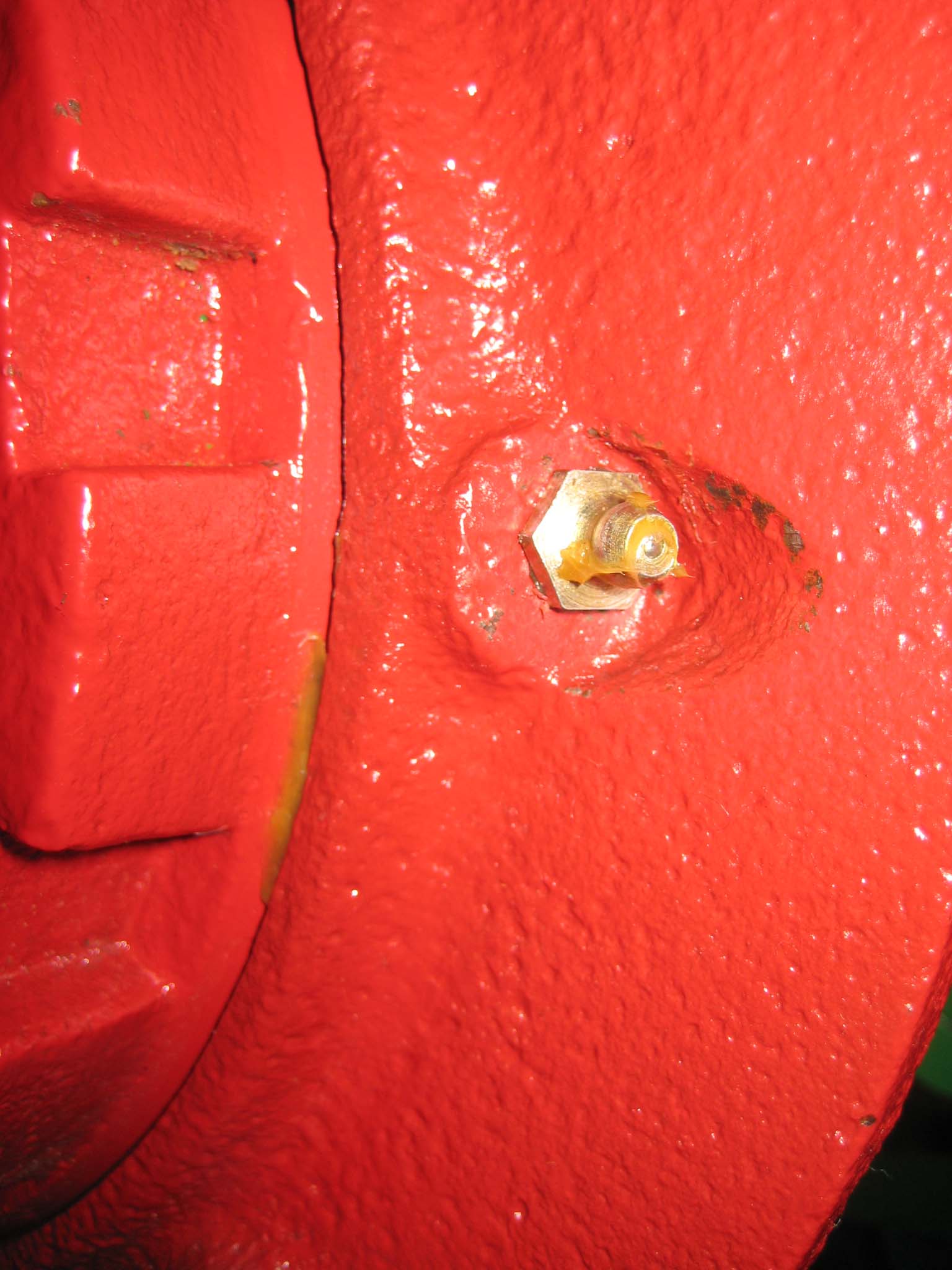
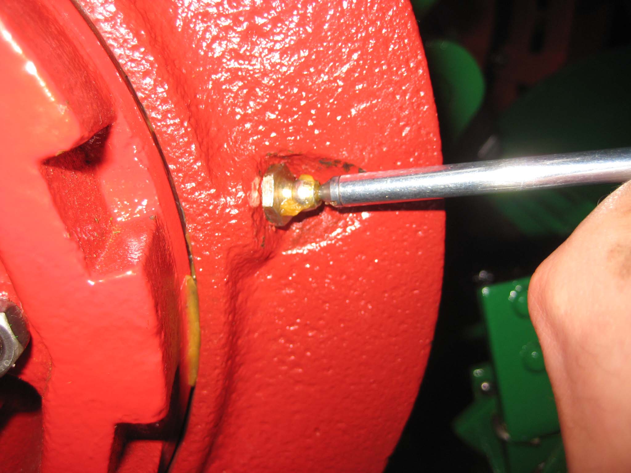
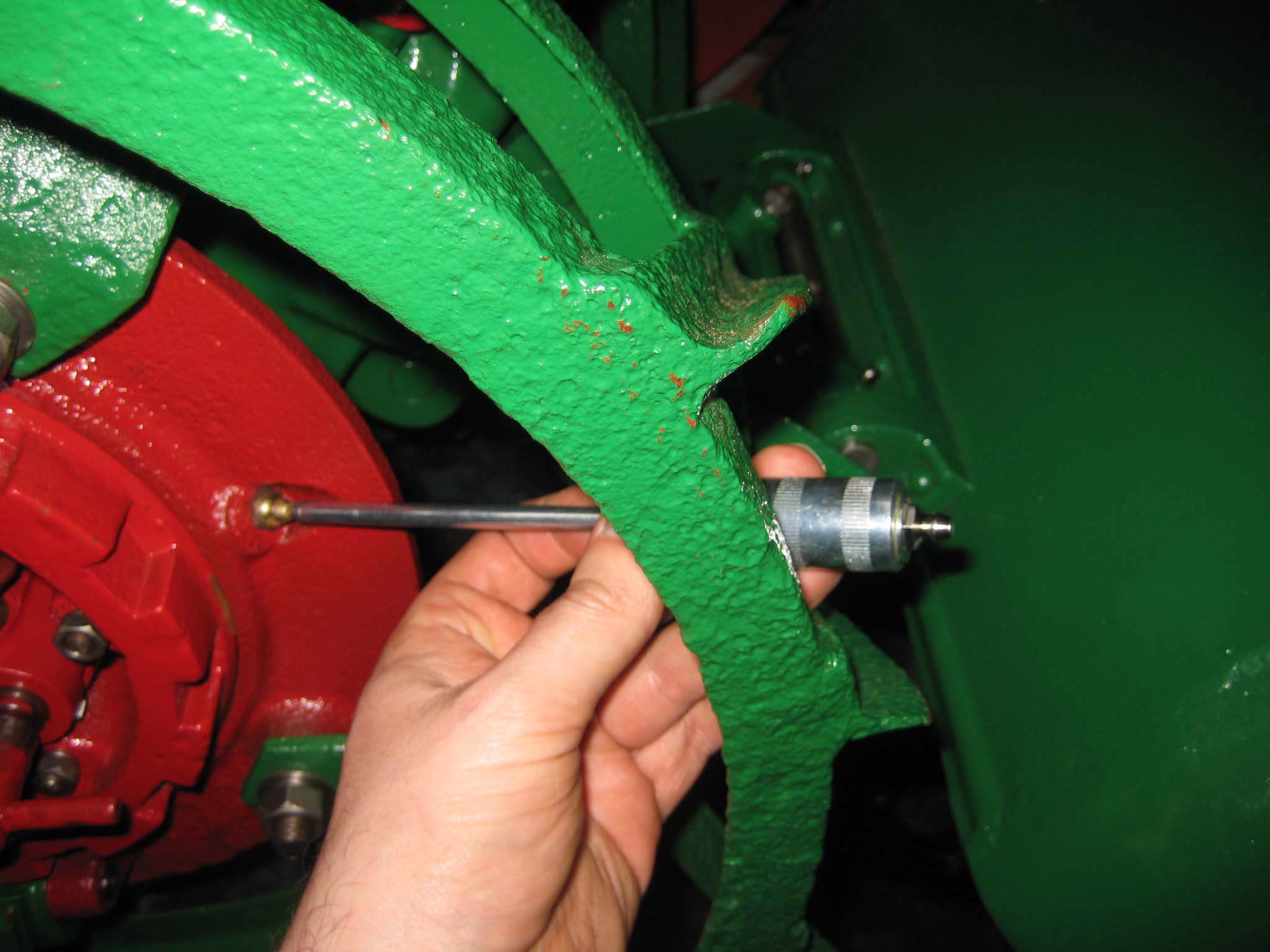
While greasing the various lubrication points on the machine in preparation for it’s maiden voyage, I discovered that whoever drilled the hole for the grease nipple on the left hand wheel hub must have been having a bad day, as it does not sit concentric with the recess in the casting (Simar 0150), which means that a standard grease gun will not fit on to it. Fortunately, I have a needle adaptor which is very handy for awkward to reach grease nipples (Simar 0151 & 152).
Much to my surprise, the Simar fired up at the first attempt, and burbled away smoothly once warmed up a bit. Unfortunately, rain then stopped play, so wasn’t able to film it’s first outing into the veg patch, so watch this space for the grand finale!!Attachments:
November 9, 2016 at 5:41 pm #22962vhgmcbuddyKeymasterWhy do you think you need a donor? What is worn? Some of the gears are available individually, as are bearing, seals ect.
November 9, 2016 at 12:24 pm #22960vhgmcbuddyKeymasterThank’s Charlie.
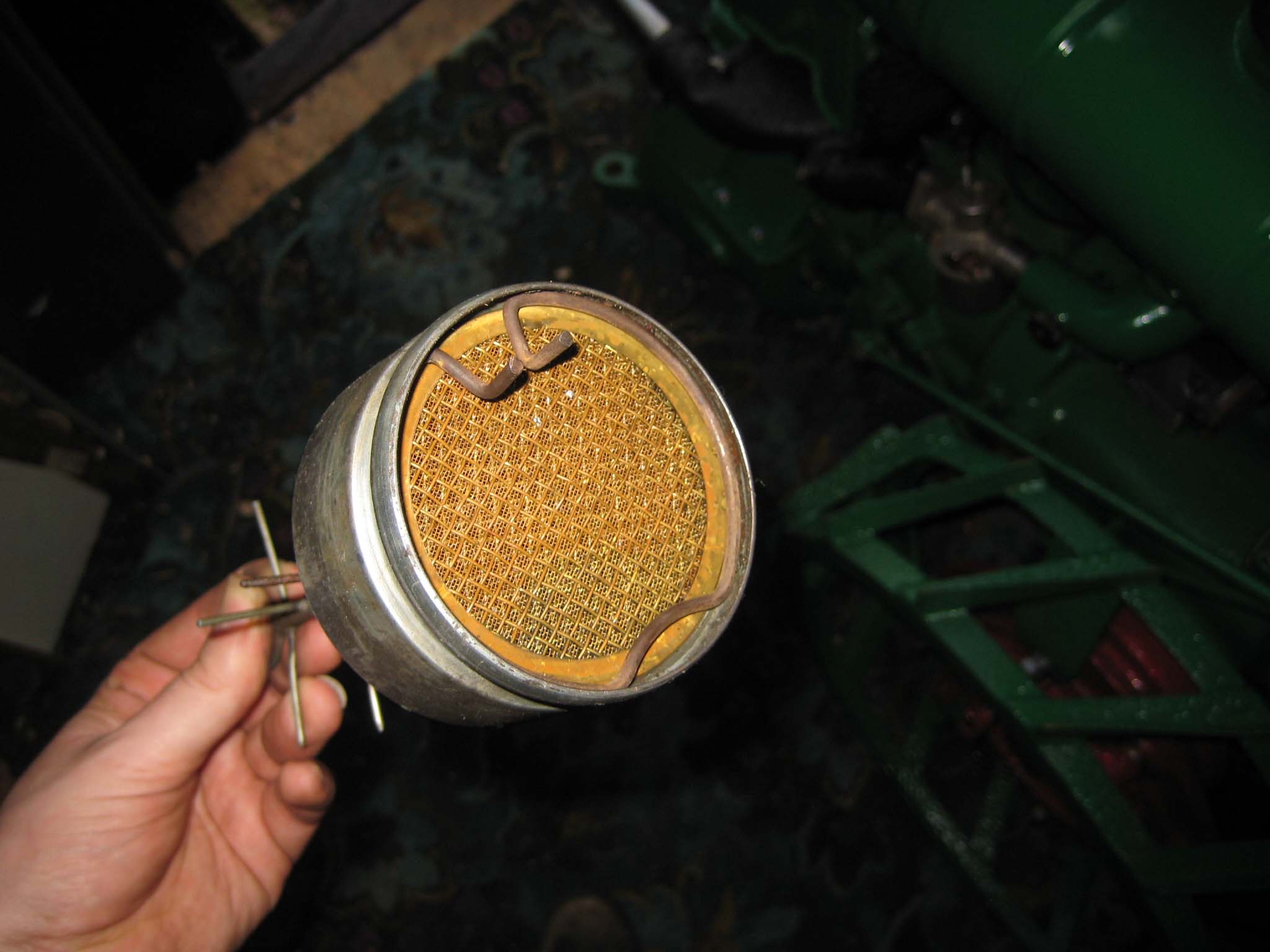
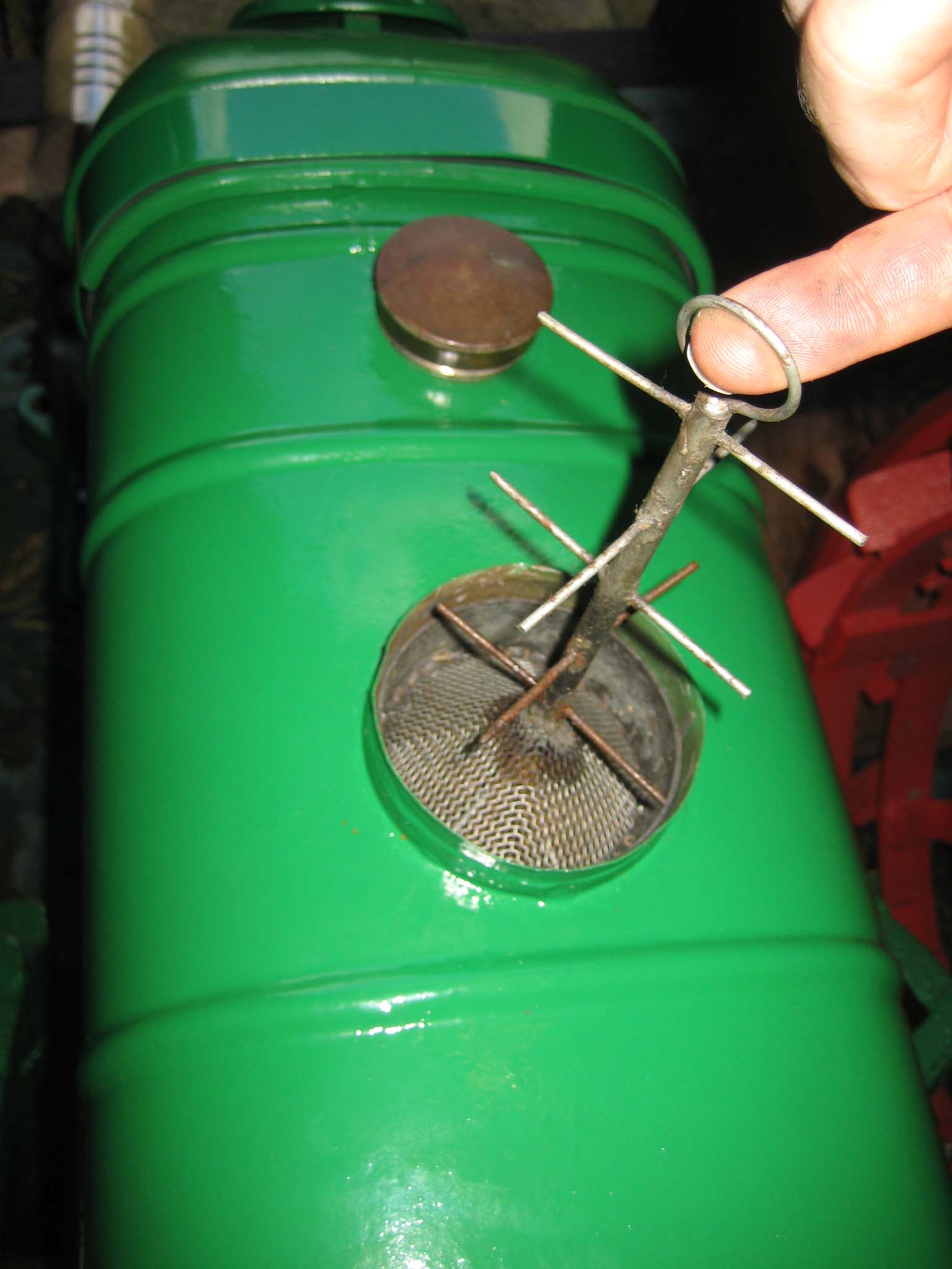
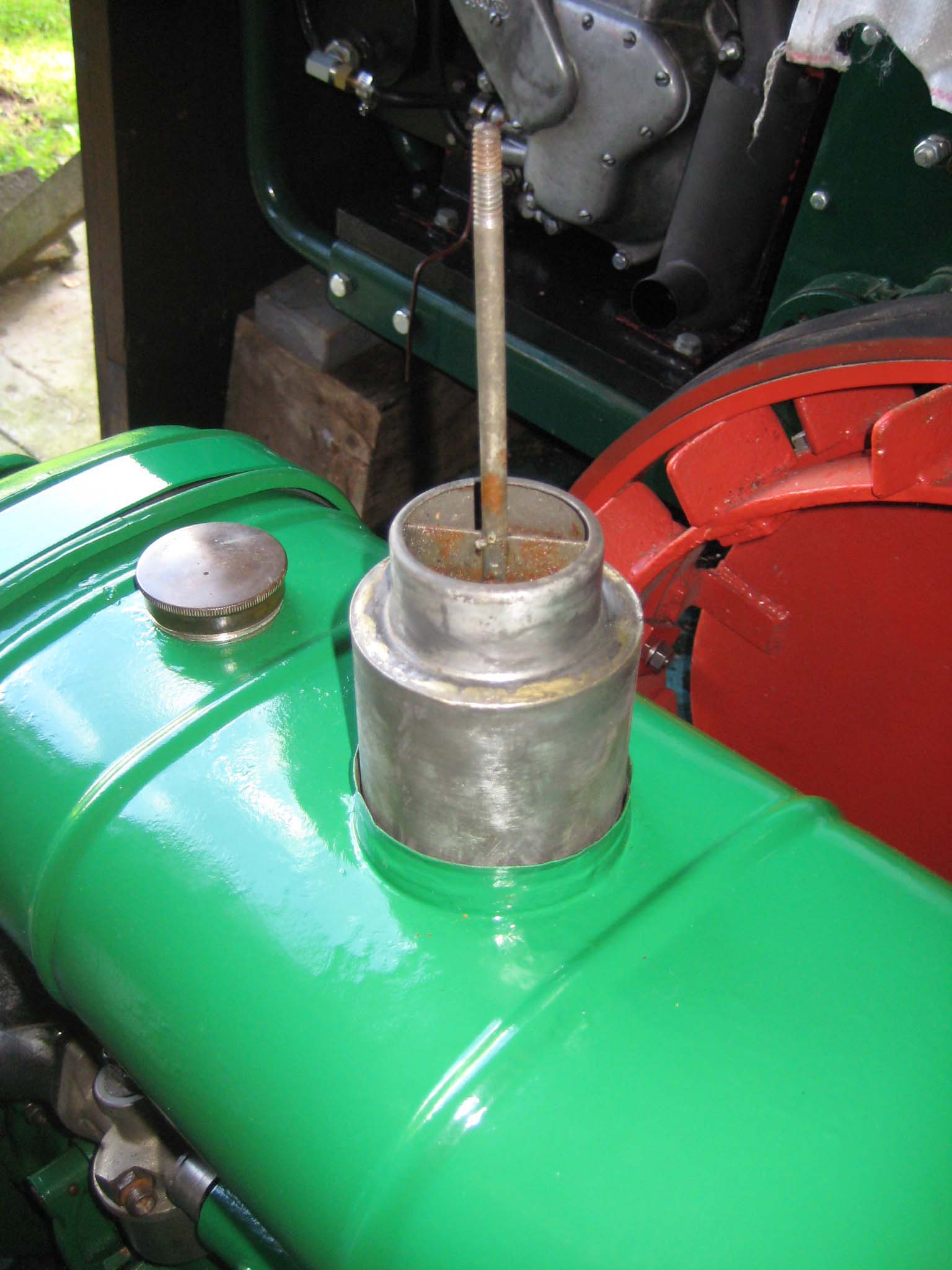
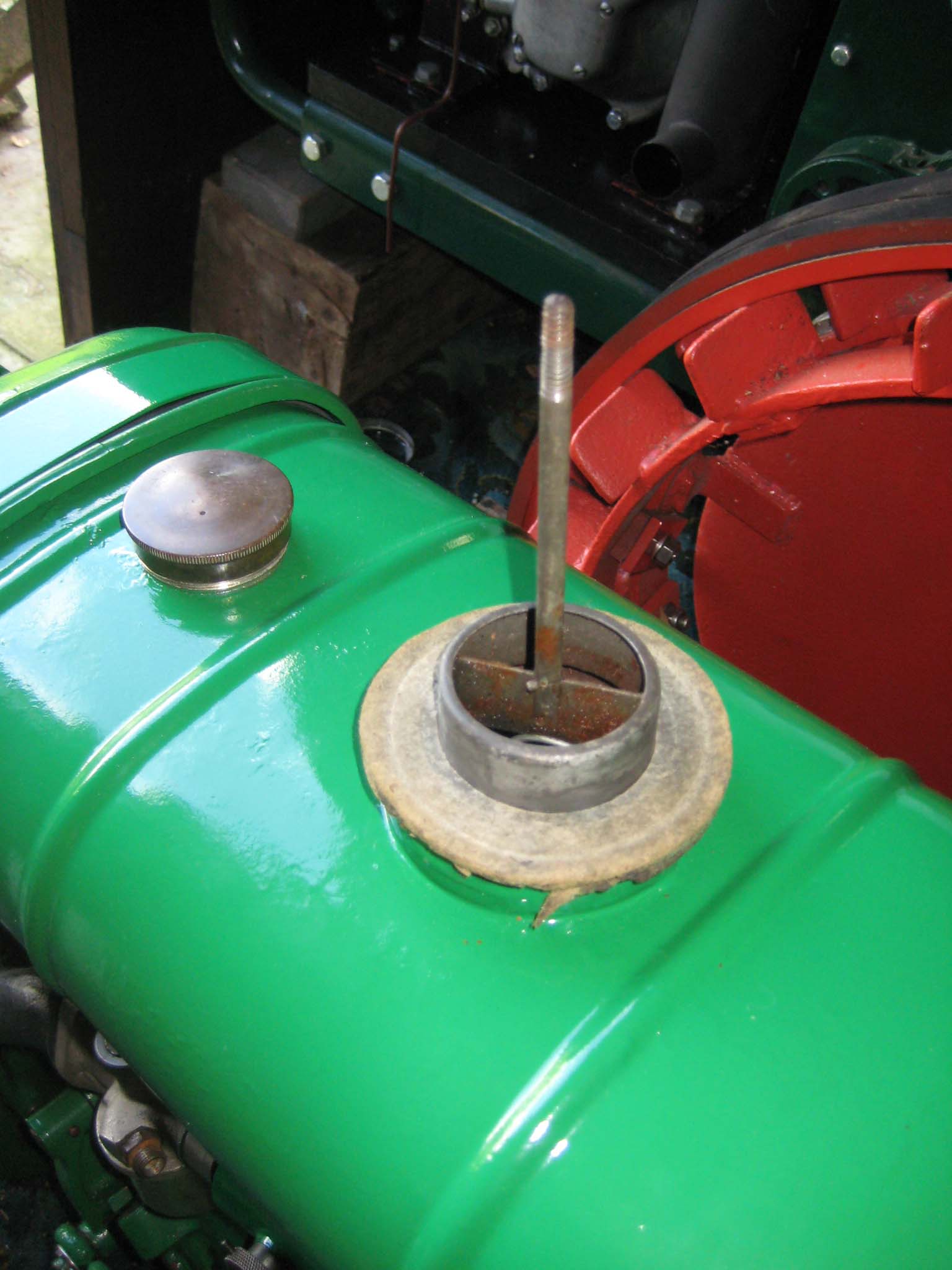
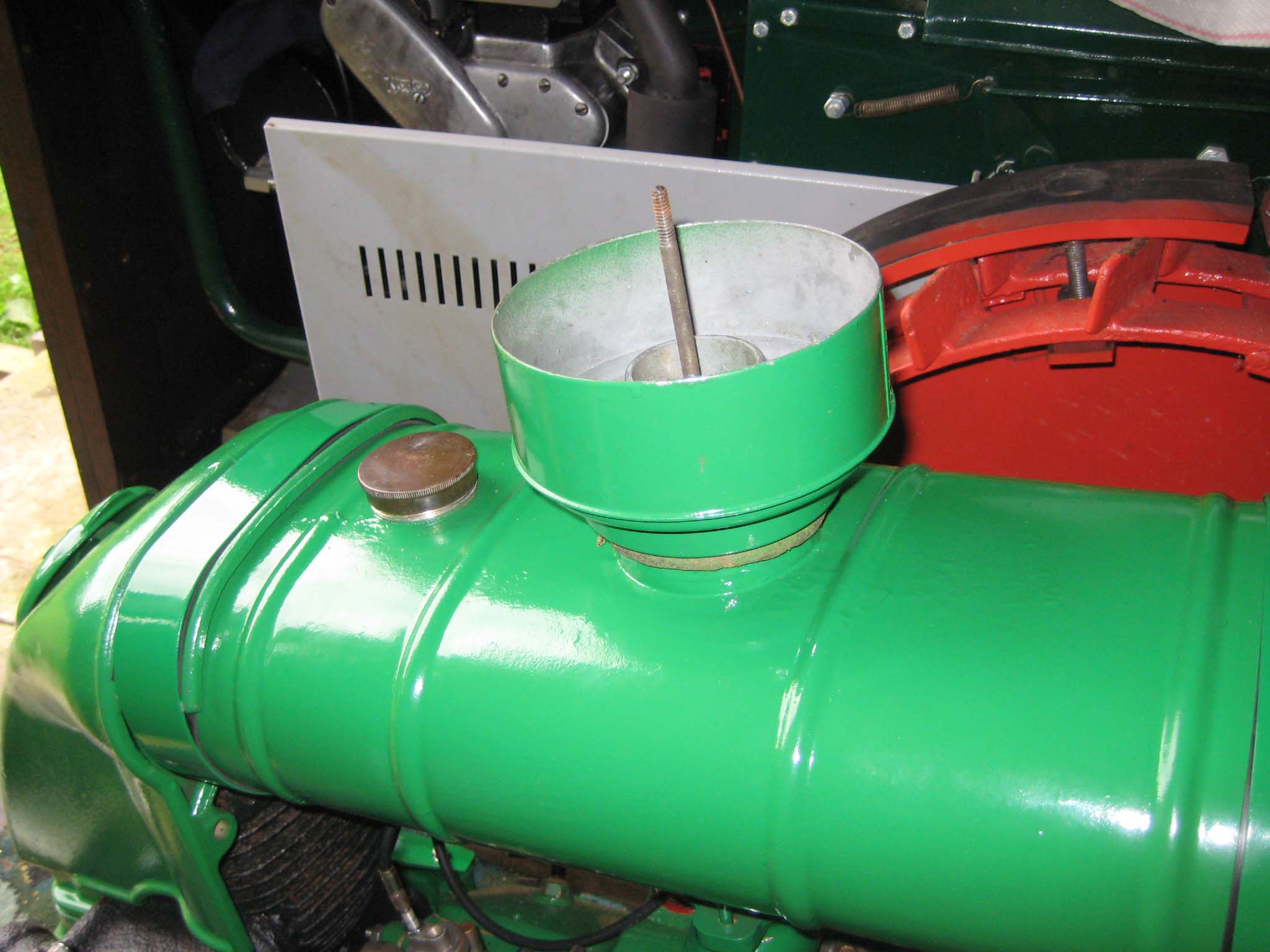
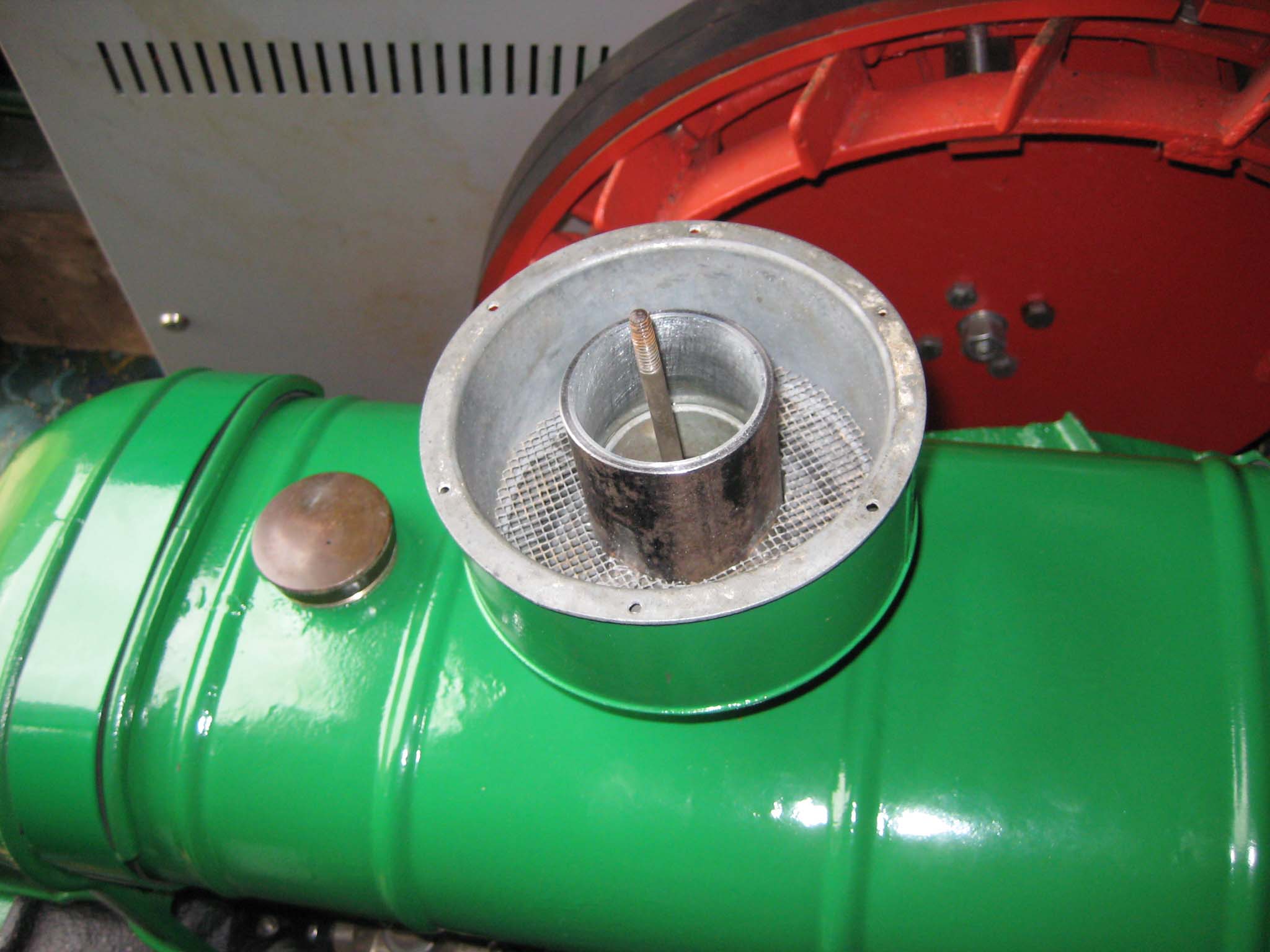
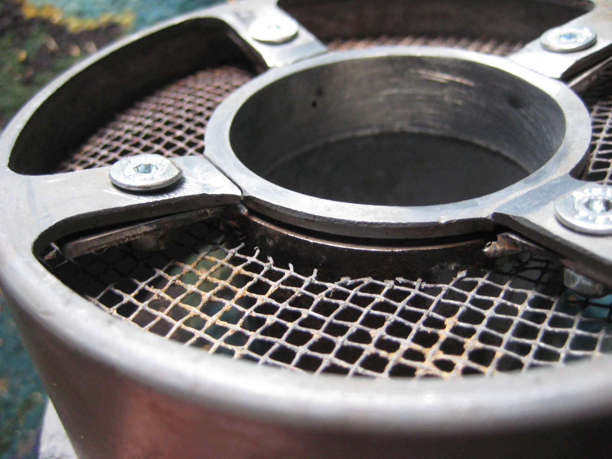
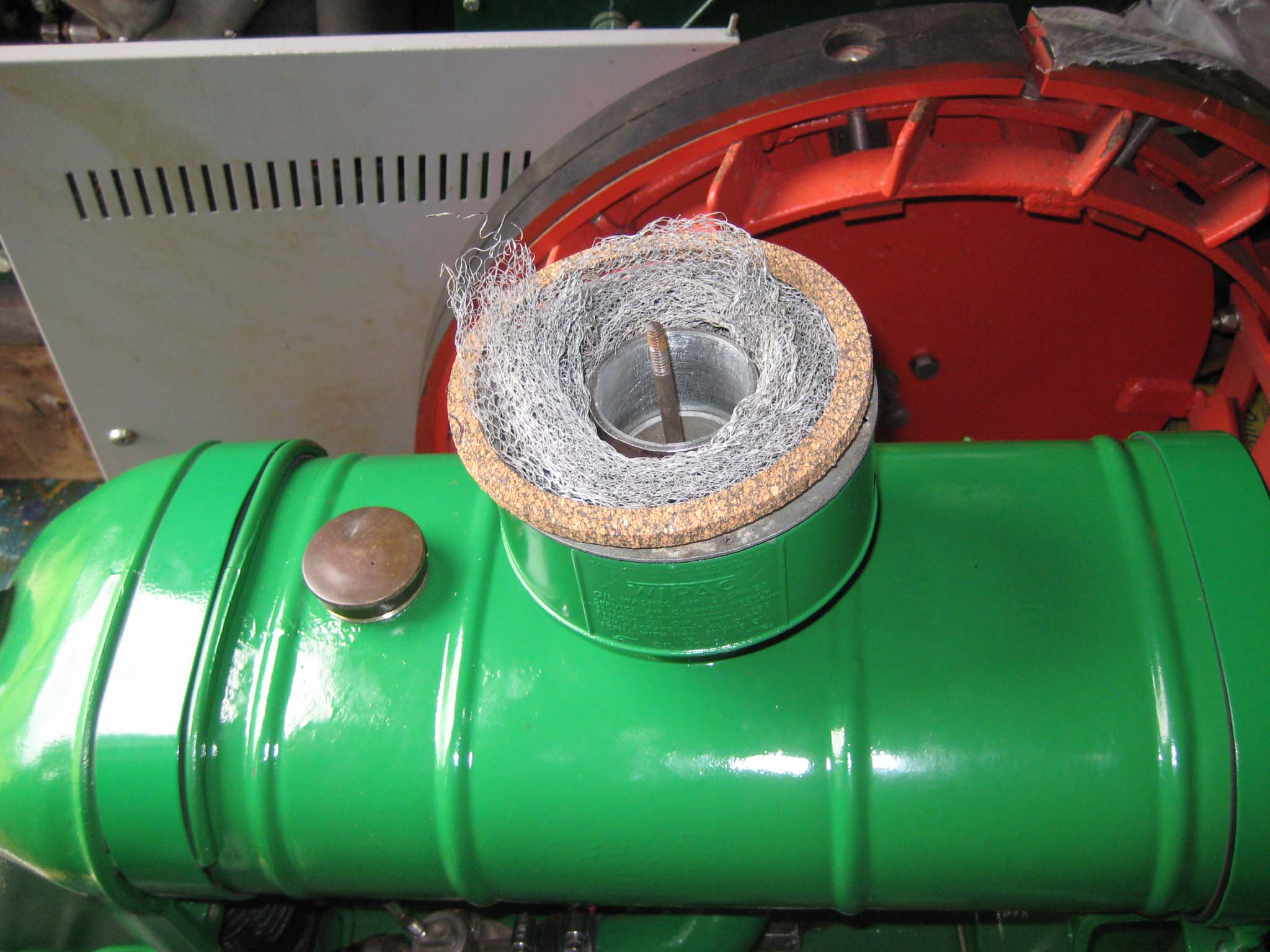
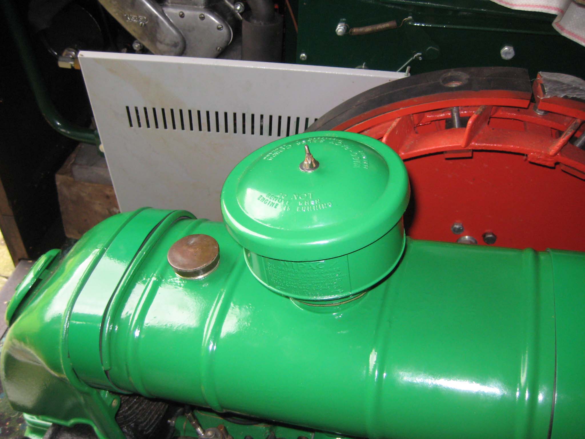
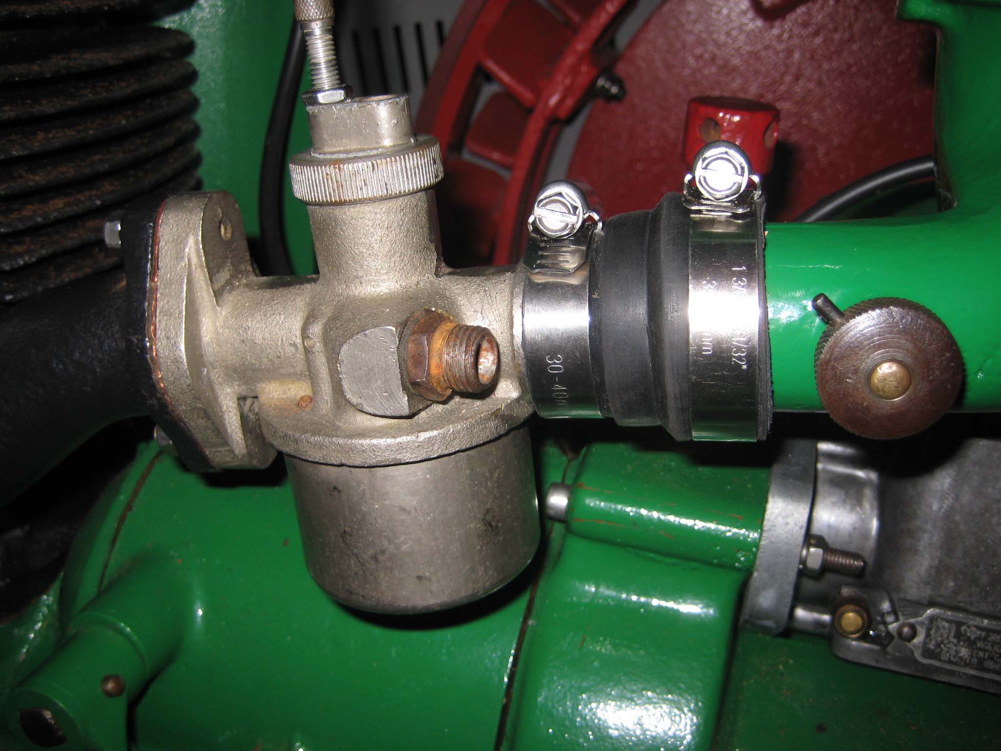
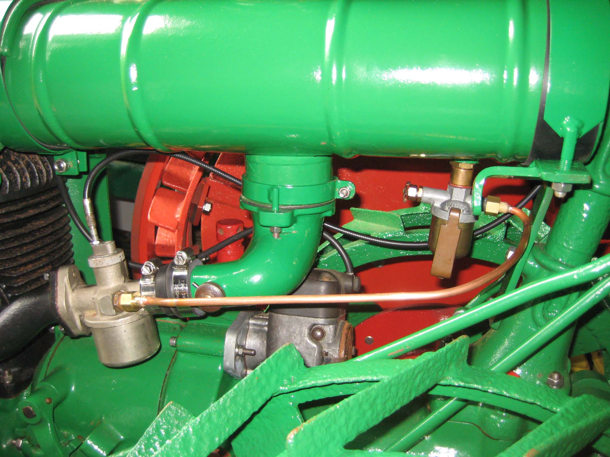
November 8, 2016 at 7:51 pm #22942vhgmcbuddyKeymasterThe air cleaner is made up of several parts. First is a holder for oil soaked wood shavings, which has a gauze on the base held in place by a large retaining clip (Simar 0136). This is lowered through the tube in the centre of the fuel tank so it sits on top of the elbow casting (Simar 0137). The wood shavings will be added when required. Next in goes the air cleaner tube (Simar 0138) onto which is fitted a felt washer (Simar 0139). The oil bath outer body then sits on top of the felt washer (Simar 0140). The oil bath has a removable inner section (Simar 0141). The four webs at the base of this item had broken where they join the inner tubular support. The oil bath seems to be made out of a Zinc alloy (appears to be the same as what carburettors are normally made from), so welding/brazing is not an option. Considered adhesives, but the contact area is very small. My local Blacksmith suggested making a Steel tube to fit over the outside of the central alloy tube, onto which were welded four webs. The whole lot was then bolted together through the new and original webs (Simar 0142). The inner oil bath is filled with a woven mesh filter and has a cork gasket which fits around the top edge (Simar 0143). The whole lot is topped off with a cover held in place by a 1/4″ UNC wing nut (Simar 0144). The air intake elbow is joined to the carburettor by a 40 to 30mm diameter straight rubber reducer (Simar 0145). A new copper fuel pipe was made with 1/4″ BSP ends and fitted between the fuel sediment trap and carburettor (Simar 0146).
Attachments:
November 8, 2016 at 8:41 am #22921vhgmcbuddyKeymasterPlonker. Im having trouble accessing my profile too. I opened a topic in Help and information. Owen.
November 8, 2016 at 2:17 am #22919vhgmcbuddyKeymasterOwen, you are a star, I am having trouble opening the message service so I can send you my email address private, so I will try again tomorrow, thanks for your help. Plonker
November 8, 2016 at 12:05 am #22918vhgmcbuddyKeymasterThanks for that – I will have to be careful tapping the bolts out as there is a slight crack in the clutch carrier around the area where the cone-shaped head of the bolt sits!
(I have had the carrier off several times whilst sorting out the clutch problem and the bolts to which you refer have not dropped out, so I assume they need tapping out gently)November 7, 2016 at 3:25 pm #22914vhgmcbuddyKeymasterHere is an extra photo with notation. I see that the Clutch base plate has 2 holes for a pin spanner? 65mm apart, 5mm diameter (I would have to make a tool). The centre spindle has shoulders to take a spanner.
Am I right in thinking using an open spanner on the spindle and a pin spanner for the holes I can remove this clutch? I show the direction of engine spindle rotation….presume you would expect opposite thread direction therefore to undo you must rotate clockwise?
Question is……rotate clockwise the plate OR the shouldered spindle (while the other is held still)?Help please!
Attachments:
November 7, 2016 at 12:23 am #22895vhgmcbuddyKeymasterSorry, can’t seem to get the hang of posting pictures – Here they are (hopefully)
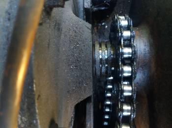
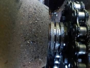
Pictures taken before I cleaned it up.Attachments:
November 7, 2016 at 12:12 am #22894vhgmcbuddyKeymasterThanks for the comments, that all makes sense. Mine does not have the washer, so I will try and locate one of those.
I took the top of the clutch housing off today so I could get to the other side of the clutch drum. There were 3 spacers (see pic) which i cleaned up with petrol and re-greased. I also added more grease to the bush via the grease nipple, this had the effect of pushing out some dirty grease. I then re-located the clutch driver and key just a fraction away from the drum. End result of all this is that the clutch now works perfectly! So thank you.
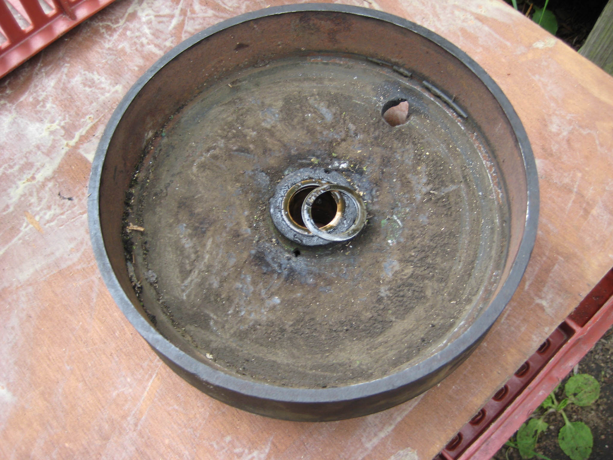
Next question – How do I remove the clutch shows from the driver, as I need to get them re-lined. BenNovember 6, 2016 at 7:41 pm #22892vhgmcbuddyKeymasterHere’s a photo of the copper washers on my Trusty. They are the same inside/outside diameter as the bronze bush in the drum.
Attachments:
November 5, 2016 at 11:38 pm #22854vhgmcbuddyKeymasterWith the knowledge you all have, I know we will get to the bottom of this problem. (interesting to know trusty220 that this is a modified crankshaft). The gap you referred to I believe to be an optical illusion as there appears to be no gap when seen in the flesh, indeed the drum seems to sit perfectly on the crankshaft.
I will try pulling the key out slightly to see what that does and maybe position the clutch driver slightly away from the back of the drum.
One other thought – Busman, in his restoration (which I have studied on this site) mentioned this: “Don’t forget to fit the copper washer that sits between the clutch drum and clutch driver, otherwise the clutch assembly can rub against the vertical face of the drum.” Well, I don’t appear to have such a washer – do I assume there should be one and if so, wouldn’t it be an unusual shape to fit over the key which sits proud of the crankshaft?Sorry for all the questions and I really appreciate the answers.
Ben.
-
AuthorPosts