Forum Replies Created
-
AuthorPosts
-
June 12, 2015 at 2:10 pm #13417
 trusty220Keymaster
What did he have to say for himself by way of an excuse??
Great result, Alan. It gives you a bit more confidence in the Boys in Blue. Well done to them as well!June 10, 2015 at 12:55 pm #13401trusty220KeymasterOne thing that I can add is that any engine parts should be easily obtainable through Kubota dealers and such items as fuel filters, even though they weren’t attached directly to the engine, were also Kubota sourced.
The hydrostatic drive motors were quite weak on these machines and didn’t have a long service life; it may be a wise precaution to change the hydraulic oil frequently to prevent too much wear.June 9, 2015 at 6:53 pm #13390trusty220KeymasterGlad to have you on board, even if it’s only temporary at present. If you are around the Peterborough area you may want to consider visiting the Holbeach Rally on 20th and 21st June. The club normally has some sort of presence there and you could have a chat with some of us- look out for Steve Woollas, he’s our shopkeeper and his picture is one the news section if you want to know what he looks like.
June 9, 2015 at 6:47 pm #13389trusty220KeymasterIf you are thinking about going to the Vintage Gathering at Astwood Bank at the weekend I will be taking my 3-speed Trusty with the fingerbar mower and riding carriage. It’s a bit of a handful but I will be only too pleased to show you how to drive it. It’s a lot simpler than it sounds! Honest!!!
June 9, 2015 at 6:44 pm #13388trusty220KeymasterYour best bet is to look up your nearest Ransomes Jacobsen dealer using the Dealer Locator on their website.
Beware, though, these were sold by Ransomes before they were combined with Jacobsen; they were not an Ipswich built product but were badged up Steiner products. What you have is the Turf Trac T-16 which was built and marketed by Steiner in the U.S.A., and were painted red when sold under the Steiner banner. They were only sold for a short space of time and came into the country in the late 1980’s whilst I was still a humble mechanic, then as I became a sales rep in 1990 I managed to sell a few before they stopped doing them (I think) around 1994.
They were sold as bank mowers and would stick to the proverbial brick wall, but they had a nasty tendency to lift a rear wheel if you decided to reverse whilst on a side slope. If you kept them going forward they were fine.
One story that I can tell you is of the boss’s son doing a demo with the larger brother, the T-21. He went down a steep hill on a golf course in Hereford with the front mower raised in the transport position. At some point he “chickened out” and slowed the tractor down, but all it did was tilt forward so that the mower was on the ground with the rear wheels in the air. This put the tractor into a very unstable condition, with the front wheels now acting as hydraulic pumps as it free-wheeled down the hill and the back wheels revolving backwards at the same speed; with the back end in the air there was no control over steering or speed and he bailed out pretty quickly, much to the amusement of the customer.
And, no, he didn’t buy one after that!June 8, 2015 at 2:55 pm #13356trusty220KeymasterKnowing what the organisers are like, they won’t turn anything away but I would ‘phone them up just to make sure that you will be welcomed.
Don’t worry about shiny paint (or the lack of it), the more exhibits the better as far as I’m concerned.
See you there on the day.June 4, 2015 at 12:27 pm #13287trusty220KeymasterThe width setting is the one on the top of the headstock. To measure how wide you are ploughing you put the plough in the ground and pull it forward to achieve it’s normal running depth. If you stand at the back of the machine and look at the landslide (or the main beam) it should be vertical- if not, adjust the angle on the two bolts that attach the plough to the drawbar. The holes are slotted so should slide easily around the tapered mandrel in the middle.
Once you know that the plough is vertical, pull it forward until it seems to settle down again then you can take your measurements.
The width is measured from the face of the disc to the vertical face of the previous furrow (the one that the right hand wheel should be in). I usually set mine to between 9″ and 10″ by turning the transverse screw on the top of the headstock. I also try to set the disc about 1/2″ to the left of the plough point by adjusting on the disc mounting slide.
The only other adjustment is the depth which you adjust on the long screw that sticks out of the back; it needs to be about 6″ to 7″ measured from the top of the vertical cut to the bottom of the furrow.
You can then adjust the disc height to suit the conditions, but I usually run with all the spacers under the slide (at very most I take one spacer out and put it above the slide); at this it usually puts the disc bearing just clear of the soil. On no account let the bearing housing for the disc bulldoze the soil because it will pick up sand and wear it out.
I hope that helps!June 4, 2015 at 7:09 am #13284trusty220KeymasterYou are quite right- there is a series of spacers on the bar which normally rust together. The easiest way to free them off is to dismantle as much as you can (take the disc off and it’s arm at least) then put the whole assembly into the middle of a very hot bonfire; I use a 45 gallon drum filled with pallet wood. At the end of the fire you should be able to pull it all apart.
The centre spindle that it all assembles onto is round bar with two flats machined on it- this leaves some large gaps down which soil packs hard, jamming the spacers on and encouraging rust to form. That’s why you have to get it all red hot to dry it out and convert the rust back into powder; it should come apart then, providing you’ve got it hot enough!
When ploughing I tend to find that the critical distance is between the tip of the ploughshare and the bottom of the disc. Normally three fingers is the gap, but so long as the disc bearing isn’t bulldozing the topsoil on the left hand side and there is some sort of gap between the disc and the share for stones to pass through then anything is correct.
Your width should be set to 9″ or 10″ and depth of work about 6″ or 7″; so long as you have the plough set around there you should then be able to set the disc about 1″ to the left of the share.
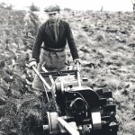
Obviously it all depends on soil type, compaction, etc., which is why different people keep winning the ploughing matches. It is more of an art than a science!June 2, 2015 at 3:20 pm #13275trusty220KeymasterOK, here goes! The definitive guide to driving a Trusty if you’ve never done it before!
1. Make sure that both levers on the handlebars are clipped back securely under their hooks;
2. Start engine and warm up so that it ticks over smoothly;
3. Stand at the back and rotate right-hand twist grip throttle until the engine is ticking over at it’s slowest speed;
4. Look down the left hand side of the transmission casing- look for the end of the countershaft which is about 3″ diameter and has four holes drilled and tapped in it- this needs to have stopped spinning before you do anything else;
5. Once it has stopped spinning you can engage drive to one or both wheels by moving the large handlebar levers from under the clips to a position towards the middle of the machine. The left hand lever controls drive to the left hand wheel, the right hand to the right wheel so that you can turn it under power. If you engage both together it will drive in a straight line;
6. Increase revs on the engine slowly by turning the twist grip on the right hand handlebar and you will find that the drive engages gradually and the machine moves off;
7. To stop just close down the twist grip throttle to allow the engine to tick over again;
8. On no account must you move the levers unless the end of the countershaft has stopped spinning.
9. To turn the tractor after driving in a straight line you must come to a stop, disengage the wheel on the inside of the turn you wish to make, then increase the revs so that the drive is taken to the one remaining wheel only. Once the tractor is pointing in the direction that you want it to, come to a stop again, re-engage the wheel and increase the revs to drive in a straight line again.
It sounds awfully complicated but it is simplicity itself once you’ve had a go. Let me know the serial number and I’ll put you on the Trusty Register with it.
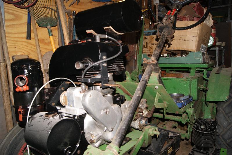
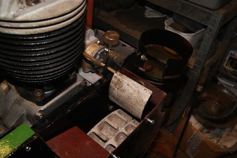
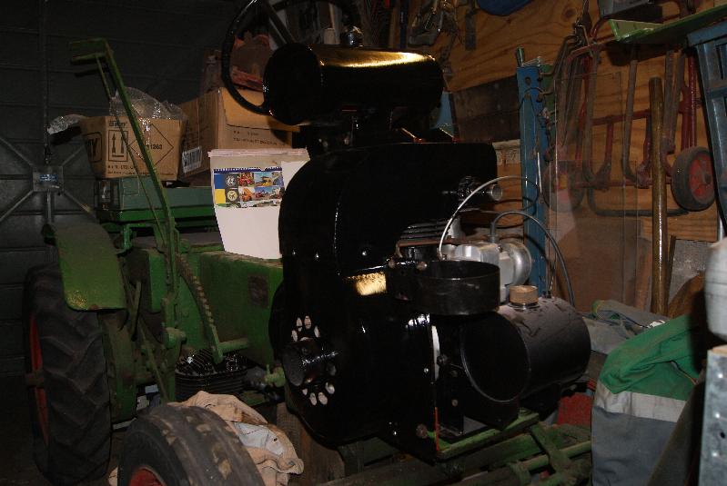
Above all have lots of fun with it!June 1, 2015 at 7:22 pm #13263trusty220KeymasterI seem to have finished the one side of the engine now, so it made sense to turn the tractor around to work on the other side.
First on was the support for the governor rod which I had already put on once; it didn’t look right, so I went back to the photo’s that I took before I took it all apart and it proved my hunch was correct. In a moment I took it off and changed it around and so now it fits as it did originally. I still need to clean the mechanism up so I haven’t put that back on the spindle yet, but turning the whole lot around will make it easier.
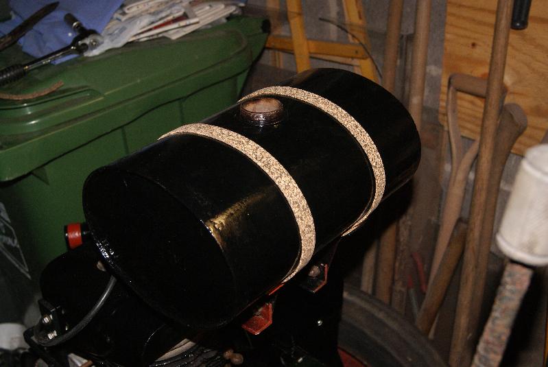
The fuel tank was crying out for attention next and so I made up some cork pads for it to sit on. It sound easy, but it took me hours to position the brackets so that the tank sat level and at right angles to everything else. I can only assume that it never has fitted properly because I had to open some of the holes into slots to make it all work. Anyway, back to the cork pads! While I was at it I also made up some cork strips to sit under the new tank straps so that the paint didn’t get scratched once it was all together.
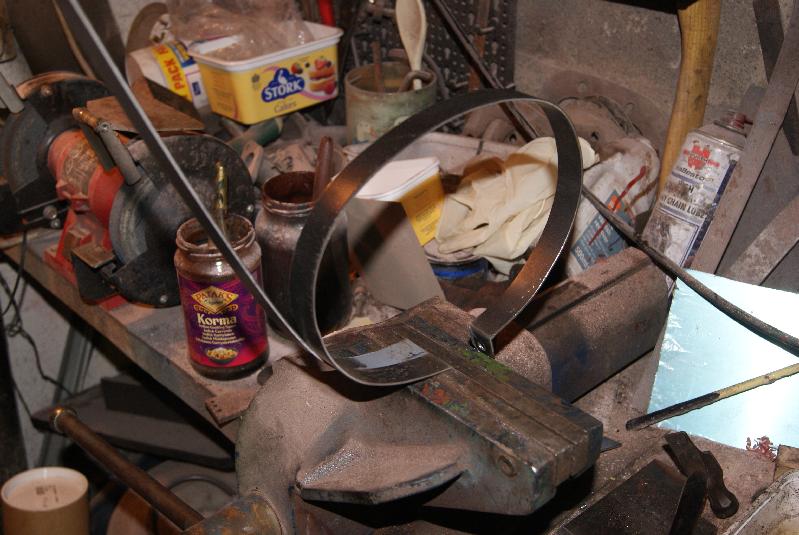
Because the tractor originally came with some Jubilee Clips instead of tank straps, I decided that it needed some proper ones that looked like the originals. The straps were made out of strip steel, 3/4″ wide and 2mm thick. Unfortunately the steel supplier couldn’t do the original thickness which was 1.75mm and my choice was either 1.5mm or 2mm; seeing as the strip has to be strong enough to take a 90 degree bend in each end for the tensioning screw I went for the thicker metal.
The hardest part was getting the profile correct because the tank is an oval one. The only way that I found to do it was to bend a little at a time and try it against the end of the tank, then do a little more and keep going until I had gone all the way around, then make the bend at the end. Once I had made one strap I put the second strip in the vice alongside it and copied the shape; from the photo’s you can see that I took a great deal of care in setting up the strap in the vice, making sure that it was perfectly square to the jaws otherwise it would end up as a giant corkscrew.
I haven’t quite finished the straps yet as I still have to paint them, but I thought that I’d do them silver instead of black so they stand out a bit.
Putting the side plate back on presented a few problems in that it wouldn’t go past the bracket for the weeder bar, so I had to undo that and drop it down out of the way. Eventually I ended up taking off the footplate to gain access because it had been put on with an odd assortment of bolts and nuts. Some were too small in diameter and had UNF threads as well; this does sound a bit daft, but when you come to undo something and find that the heads are AF instead of Whitworth (or even worse, METRIC!) then it does make sense to keep them all the same type. After all, it was built in Whitworth sizes so it should fit together better using them.Attachments:
May 29, 2015 at 5:20 pm #13195trusty220KeymasterAGM’s are always a tricky subject because club members generally aren’t interested in attending; whether it’s the fear of being voted onto committee or just being bored to tears, the reasons are many and varied.
This is true of most clubs (note I say most, not all!) and it sounds like Andrew has had a poor experience with the OLC. I would be lying if I said that our AGM is well attended, but it really is the only place that members can air their views and I would like to see more members at our AGM in future.
Does anyone have any bright ideas as to how to remedy the situation? We have held it in the Midlands over the last few years to make it fairer for all with a central location; we have tried to provide something interesting to visit at the same time.
We are open to suggestions for next year.May 27, 2015 at 5:42 pm #13175trusty220KeymasterI’ll blame it on the neighbour’s motorbike! Forewarned is forearmed, so they say!
May 27, 2015 at 2:58 pm #13172trusty220KeymasterI’ve consulted Tony Cooper (the bloke who rebuilt the magneto) and he says that whilst it won’t hurt the mag to use a resistor plug you get a far better spark by removing all of the resistance out of the line.
I will now look for a straight B6ES plug or equivalent and replace the suppressor cap with a brass connector that joins straight onto the plug.
Thanks for spotting that potential problem!May 27, 2015 at 7:16 am #13167trusty220KeymasterI had a feeling that there was something about it as well but couldn’t find the topic on the forum. I asked as many people as I could and the answers that I got were generally of the sort that it didn’t matter.
Now that you have put an element of doubt in my mind again I will give the Magneto Man a call for a definitive answer once and for all.
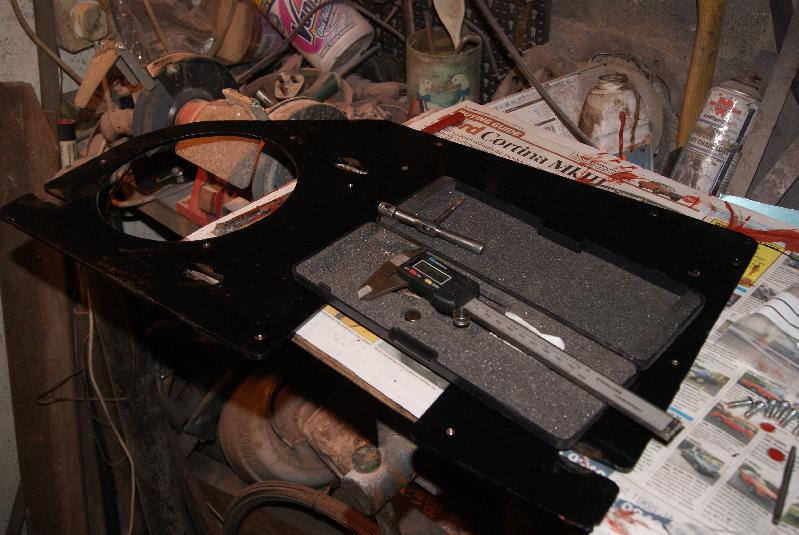
Watch this space.May 25, 2015 at 6:24 pm #13146trusty220KeymasterBoring is not the word, it seems like three steps forward and two back. After endless layers of filler, flatting down and ghosting over with paint, then flatting and repeating over and over again, I’ve finally got the lower cowling into a reasonable shape and finish. I then found that I had to take off the top cowling to fit it- fine, just four bolts to undo. Until the fourth one stuck in the head nut, that is, and brought the nut and stud out with it!
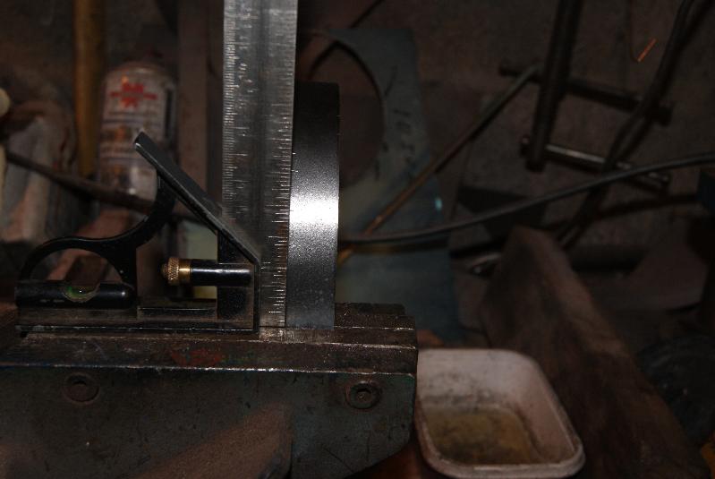
Cylinder head off again so that I could screw the stud back in without bruising the threads. Whilst it was off I checked the alignment of the starting pulley and the locating screw for the strap- if you remember it should be at 12 o’clock when the piston is on TDC- and this gave me some satisfaction as it was spot on.
Head back on again, but this time I thought that I’d check the screw holes that hold the cowling onto the side plate. These screws are 3/16 Whitworth and so are tiny, and I remembered that when they came out they were quite an assortment of odds and ends. A quick trip to the nut & bolt suppliers had 2 dozen bright shiny screws for £2! Being Whitworth I think they’d been on the shelf for a long time and I was really contributing to the storeman’s Christmas Beer Fund.
For the sake of taking four bolts out I thought it best to run the tap through them whilst it was on the bench, so that’s what I did and I’m sure they went in better for taking the time to do it.
Re-fit the side plate to the tractor, fit the clutch cover with it’s three screws and then fit the lower cowling with it’s seven screws; the two at the top on the front are bolts that hold the bracket for the governer vane, so don’t go putting screws into those!
Next was the governer vane that fits close in to the fan, followed by the bracket that fits diagonally behind the top holes of the lower cowling. Then I could re-fit the top cowling and the tank brackets.
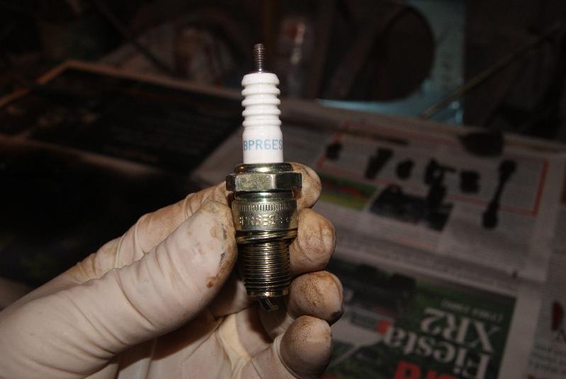
A few weeks ago I mentioned that the spark plug for these engines should be a KLG M80. This is an 18mm plug and somebody has modified this cylinder head to take a 14mm plug- good idea because it is difficult to buy 18mm plugs these days, but what plug do I use now?
At work we sell NGK plugs and so I went through the cross-reference book to find the answer; the direct equivalent is the NGK A8, but as this is still an 18mm thread this was only halfway.
The “A” signifies the 18mm diameter thread, and “B” signifies the 14mm diameter thread so it had to start with a “B”. The “8” is the heat range of the plug and so I had to try to find one with a similar number, but talking to a kind man at NGK he suggested going to a “6” to compensate for the modern fuels.
Next came the length of thread, which in the case is 19mm, and the letter that denotes this is “E”, so I was looking for something along the lines of B6E as a basis. Nearest that I could find from stock at work is the BPR6ES- the “P” means that the centre electrode protrudes a little from the shroud, the “R” means that there is a resistor in the plug and the “S” on the end just means that it is a standard copper core electrode.
Problem solved!Attachments:
-
AuthorPosts