Forum Replies Created
-
AuthorPosts
-
May 20, 2015 at 3:27 pm #13131
 trusty220Keymaster
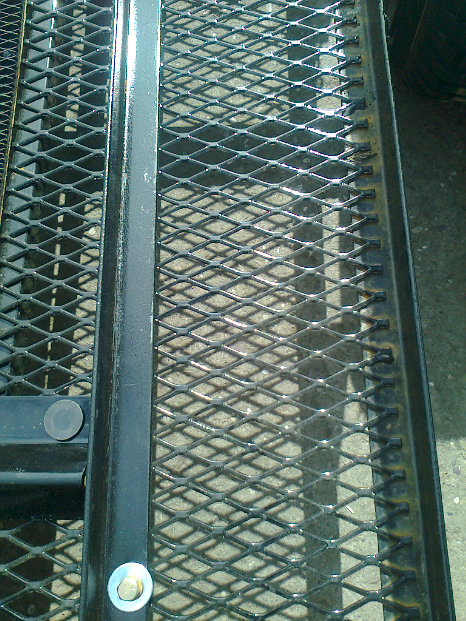
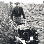
I’ve just seen something that may help- it’s an expanded mesh on a small trailer that we do. When I say expanded mesh, it’s not like the sort that we get over here; this stuff actually lies flat and would weld to a flat plate to reproduce what you’re looking for. The trailer is made by a company in the USA called Smithco and I’ve included a photo of the mesh.
Before you ask- no, I can’t get the mesh! The Smithco products are brought into this country by Ransomes Jacobsen and they won’t supply raw materials like this. The reason that I included it is because it is obviously freely available in the US.Attachments:
May 19, 2015 at 8:58 am #13121trusty220KeymasterThe reason that the Newark Show was in question is because Morton’s Media ( and Tractor and Farming Heritage Magazine in particular) has always sponsored this show in November.
Being a far larger show than Malvern it obviously has much greater costs associated with it, and with no sponsorship forthcoming from the usual place then it’s not unreasonable to ask if it will continue in the same format.
I fear only time will tell….May 17, 2015 at 6:00 pm #13106trusty220KeymasterNot a good week, this week! Nothing wrong with the Trusty, but “She who must be obeyed” lost her car keys in a 6 acre hay field on Tuesday and it cost nearly £200 to sort it all out! Needless to say, I’ve spent an awful lot of time walking around looking at grass this week before finally admitting defeat and calling in the locksmith.
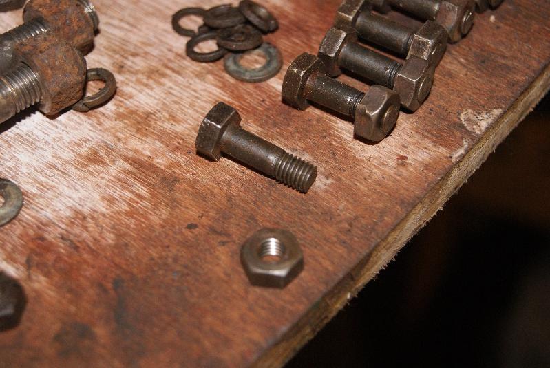
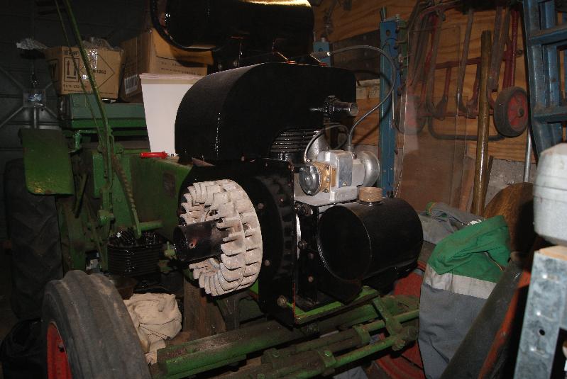
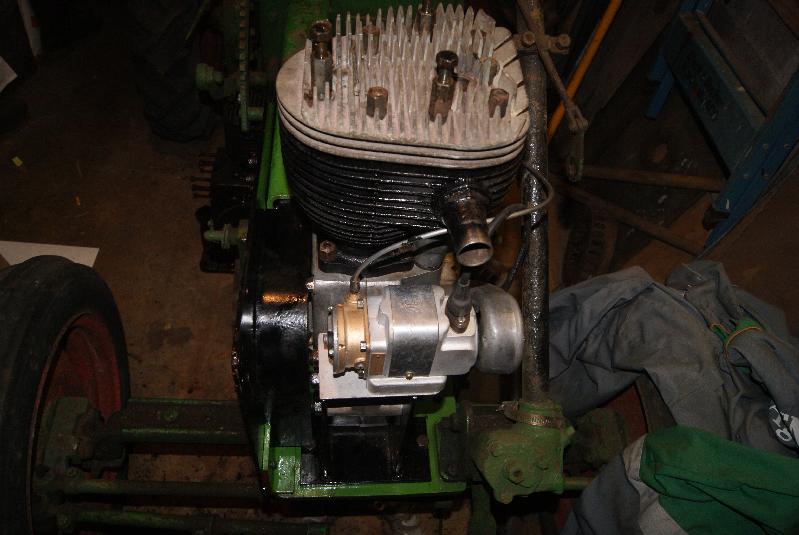
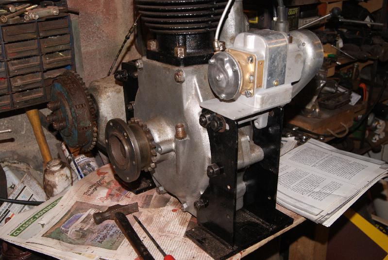
The engine is coming along well at the moment and I’ve mounted the starting hub/cooling fin carrier onto the crankshaft. There is a right way and a wrong way to do this, and I think it had been fitted wrongly previously. On the casting is a hole with a small cheesehead screw threaded through and a nut on the back; the main use for this is to provide a firm location for the starting strap so that it doesn’t slip, but it also has another use- when it points to the 12 o’clock position it indicates that the piston is at TDC. This is invaluable when you come to time it up with a replacement magneto. There are six bolts that hold the carrier on to the crankshaft sprocket carrier and so there are a potential six different positions that it can be mounted in, so beware.
Whilst we are talking about these bolts, you can see from the one photo that these are originally quite long bolts that have been shortened. Another indication that these tractors were largely hand-built.
The oil tank has also been mounted on the front engine mounting; a word of caution here because the holes in the engine mount are tapped as well, so don’t go thumping them with a big hammer to get them out after you’ve taken the nut off because you won’t do any good!
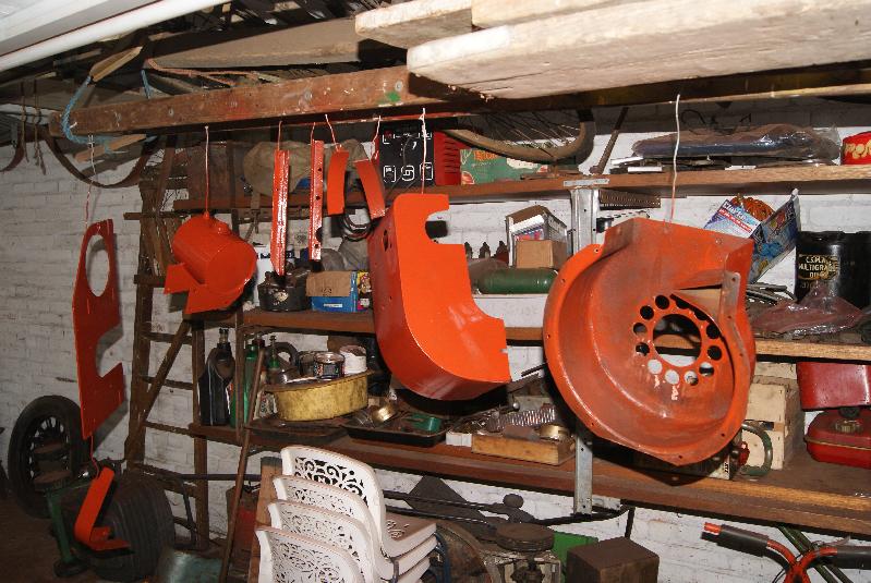
Back to metal bashing again for this week and the final batch of cowlings that have to be finished off. There is the large fan casing that has to be repaired and flattened as well as the Burgess air filter and the clutch cover; looks like another boring week ahead!Attachments:
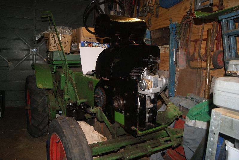
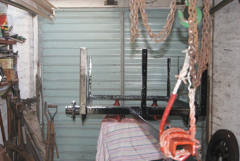
May 10, 2015 at 5:38 pm #13006trusty220KeymasterI’ve had a good weekend so far with the Steed. You can judge for yourself from the pictures and I think you will agree that it is definitely “coming on”.
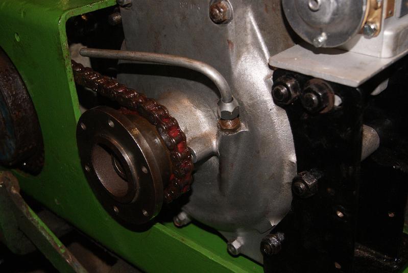
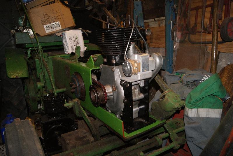
First up this week was the fitting of the main drive chain from the gearbox to the rear countershaft. If you’ve ever done this for yourself you’ll not be surprised to hear that it took me a couple of hours; running the chain through the backbone chassis was easy, it was the joining of it that was the awkward part. You can see from the picture that the grease was very well smothered all over the chain before I started and after I’d finished it was all over me! Never mind, the important thing is that the grease is inside the chain as well where it needs to be and I’ve now broadened my vocabulary of swear words. Needless to say, Ruth kept well away!
Once the chain was on it was tensioned up by levering the engine/gearbox assembly forwards. It is quite noticeable on this Steed that the engine mountings have “T” nuts in the slots to help with adjustments and to keep the engine in line; the Steed that I have does not have these nuts and so I presume they were found to be unnecessary. You can see one in the photo’s.
With the engine firmly bolted down the right hand side plate can be fitted. The correct position for this is centrally around the crankshaft (it is on slots for adjustment backwards and forwards) and you can see now why I opted to paint the front of the chassis when I did. Don’t forget to fit the crankcase breather pipe at the same time and position it so that it drips onto the primary chain. The chain cover can now be fitted.
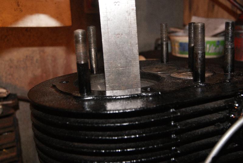
I went to the top of the engine next and fitted the cylinder head. You can see from the pictures that I tried a couple of plugs in first to see what reach I needed. These engines originally had an 18mm plug fitted (KLG M80 is the recommendation) but this one has been modified to a 14mm plug hole, so I’m going to have to do a bit of detective work to find what plug will be best. You can see what happens if you fit a plug that is too short- yes, it works, but you get a coke build-up in the threads that can be difficult to clean out. It’s better to do the job properly in the first place and make sure that all the threads are covered.
Above the piston there is also a tapped hole with a blanking plug in; this is to help in timing the engine so you don’t have to remove the cylinder head to measure the 3/8″ BTDC. On my Steed there is a little flat plate held down with a single screw to give you access to this hole, but this engine doesn’t have that plate.
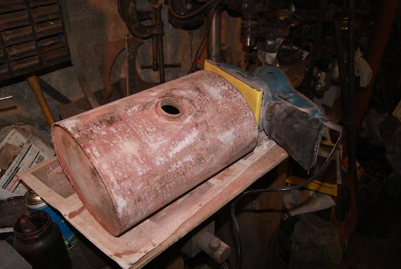
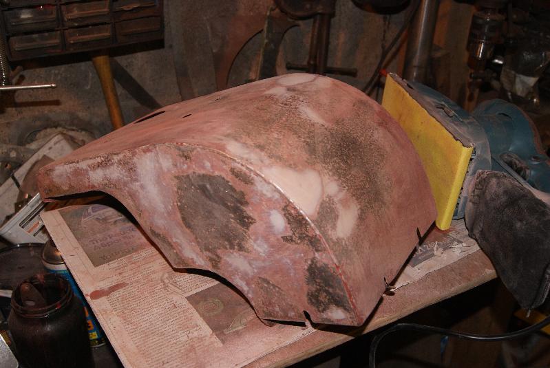
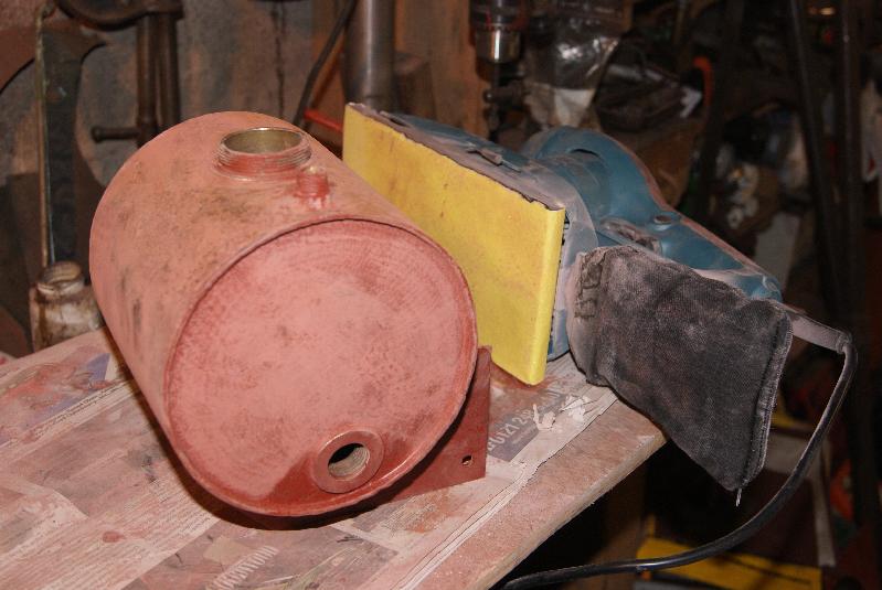
You can see from the pictures that I put the air cowling on, held down by the two petrol tank supports and I even placed the tank on to it’s mountings to take the picture. I have got to make some straps to hold the tank on with (it was held on with large Jubilee clips) and find some felt for it to sit on; one of the original problems with the engine was that rust kept blocking the carburettor and so I have steam-cleaned the tank out with some fine gravel in it to knock the rust off and then I will treat it with a tank sealer (Philip Plotkin has recommended “Slosh” so I’ll try it out) to completely cure the problem.Attachments:
May 8, 2015 at 7:04 pm #12967trusty220KeymasterYours hasn’t gone walkies, it’s just that certain events have conspired against Alan (Will Haggle)recently. For a wider explanation have a look at “The Cultivator” thread in the General section.
It is at the printers at the moment and will be posted out very shortly.
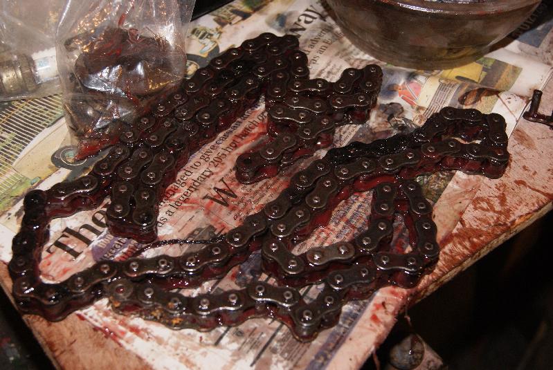
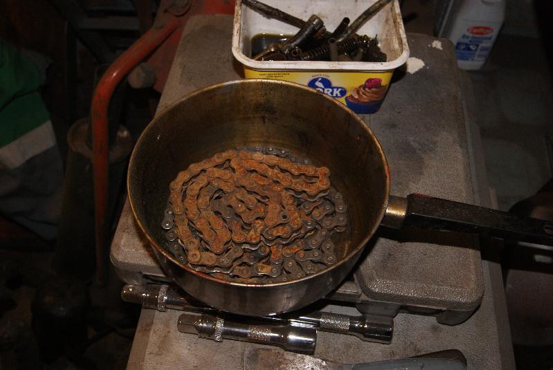
I’m sure that Mr. Haggle will be looking forward to your rally reports to put in the next issue.May 6, 2015 at 7:28 pm #12946trusty220KeymasterThe primary drive chain is next to go on, but first it had to be treated. I already cleaned it in de-greaser then steam-cleaned it to get rid of all the dirt, but the one thing that I forgot was to protect the bare surface after I did it.
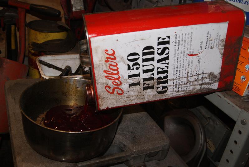
No matter, some of the links were showing a slight film of rust but no more; one thing that I always do with chains is to give them a boil in grease so that they are well lubricated from the start. As the grease heats up it becomes fluid and also heats up the chains. The air in the links in the chain is usually forced out and the grease dragged in as it cools. The only problem is that it’s a bit messy and smelly and so I usually have to do it in the garden.
When our neighbour cooks sausages (or bacon) for her kids she always seems to set her smoke alarm off; when they hear the alarm, her two boys shout, “Dinner’s ready!”
Anyway, I digress. The chains are now cooked so I fitted the primary tonight and tensioned it up using the tensioner provided at the top of the rear engine mount. There was nothing stopping me from putting it back into the chassis, so I struggled and dropped it in as well.
The next stage will be to fit the main drive chain from the gearbox to the rear cross-shaft, then slide the engine forward to tension it up and bolt it down.Attachments:
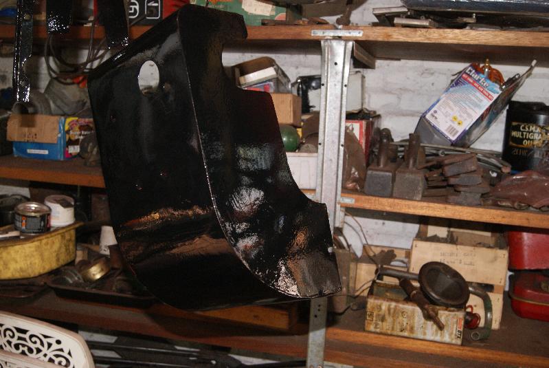
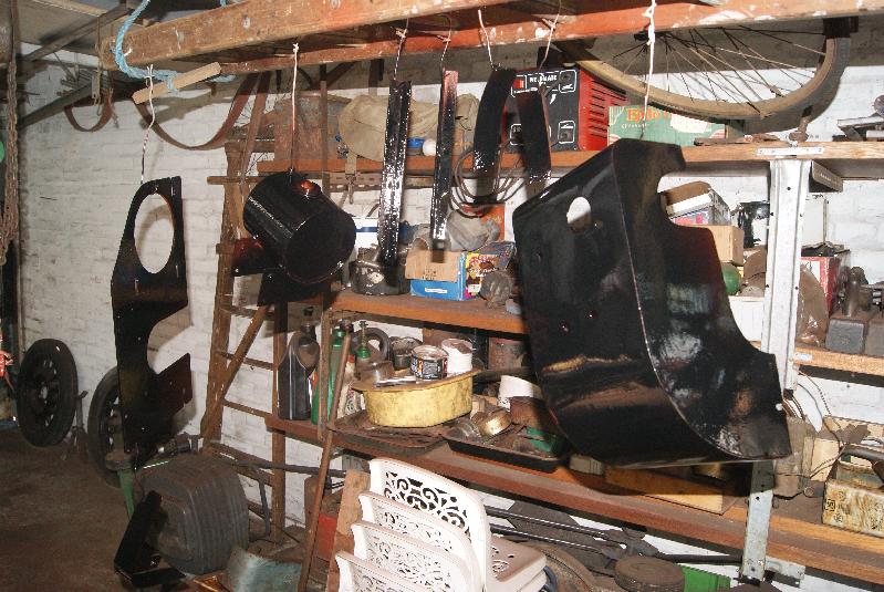
May 4, 2015 at 5:12 pm #12891trusty220KeymasterI’ve been working on various parts of the engine most of this weekend; I must confess that I haven’t taken many pictures of the tinwork in it’s various stages because they all look the same, you just have to keep flatting down and repainting until you’re satisfied with the finish. Needless to say that the pictures showing the panels in gloss black were only halfway there, I had to flat them down again and re-fill some blemishes that I wasn’t happy with.
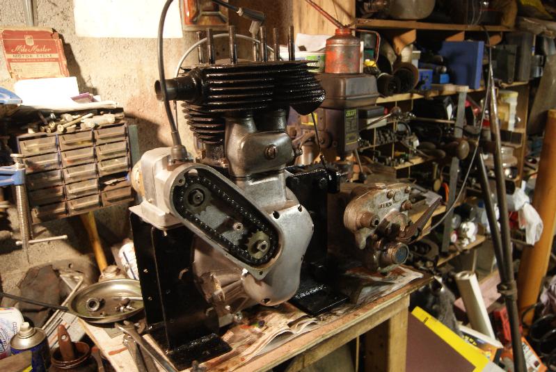
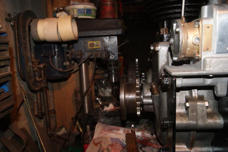
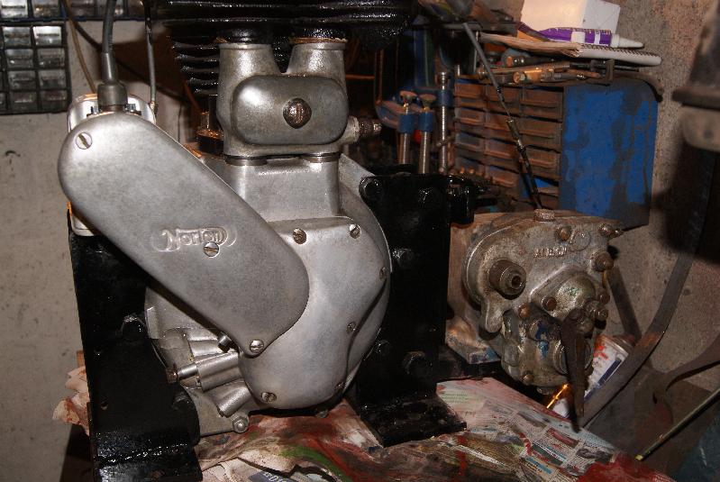
The pictures this week show that the gearbox and clutch are now back together and working so I mounted them on the platform fixed to the rear engine mounting.
At the front of the engine I have added the timing chain and sprocket to the inlet valve cam; don’t be tempted to put the sprocket on first because the chain won’t go on the teeth once the sprocket is bolted down, so you have to do them both together.
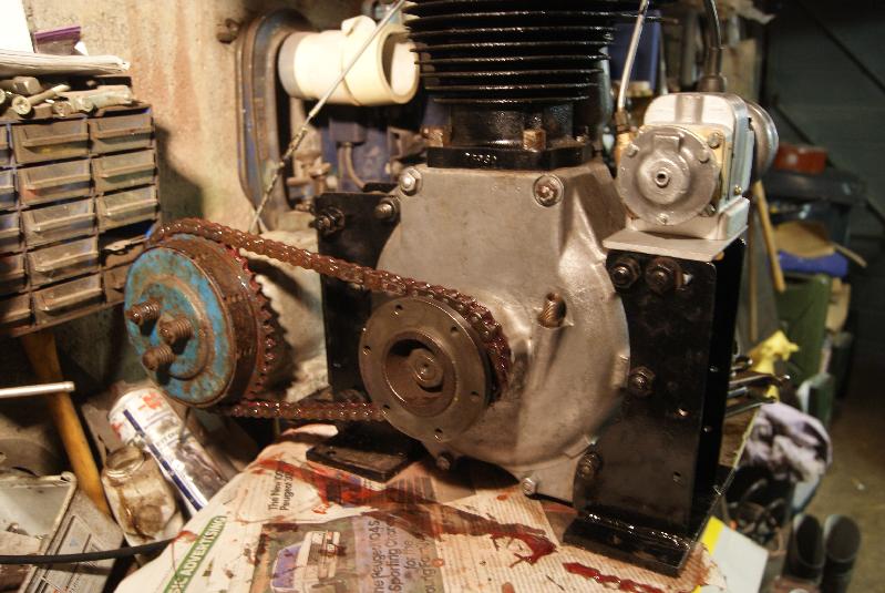
The magneto was added next and the sprocket placed on the tapered drive shaft loosely; the magneto was moved on it’s slides to tension the chain then the mag could be timed up. I’ve been asked quite a few times over the years how this is done, so I’ve included a few detailed photographs to explain the procedure.
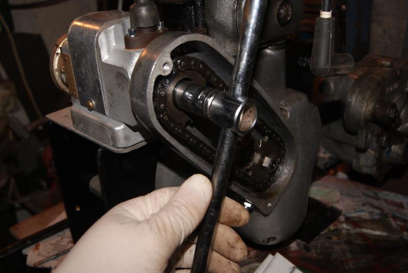
Firstly you need to turn the engine in it’s normal direction (anti-clockwise as you look at the crankshaft drive sprocket) until you reach Top Dead Centre (TDC) on the POWER stroke. This is when the piston can be moved up and down the bore either side of TDC without either of the valves moving. This is where some people go wrong- they put the piston on TDC with both valves “on the rock”, which means that the inlet is just opening and the exhaust just closing.
Assuming that you have found the correct part of the 4-stroke cycle for TDC you then have to move the crankshaft backwards until the piston has descended 3/8″ down the bore- this is known as 3/8″ Before Top Dead Centre (BTDC). When the engine is running this is where the spark should be triggered. The engine is now in the correct place for the set-up, so don’t move it from this position.
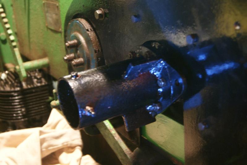
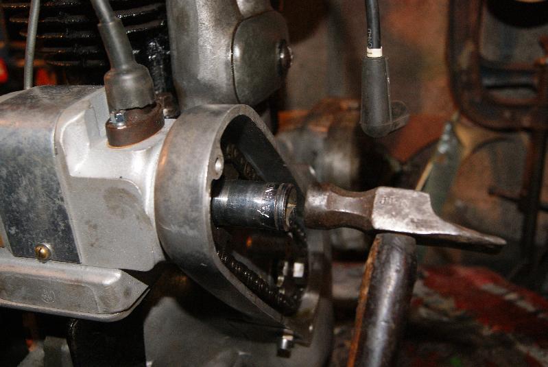
Next you turn to the magneto and remove the points cover (or contact breaker cover depending on how posh you are). If the mag has an advance and retard device set this to normal running, i.e. fully advanced. With a magneto you will find that when the points open the spark is generated, so to find when the points open the easiest way to tell is to put a cigarette paper in between the contact faces, turn the magneto in it’s normal running direction to allow the points to close, then keep turning until they just start to open again- this is where the spark will be triggered, so you stop turning as soon as you feel the paper coming loose, then take a tubular drift and tap the drive sprocket onto it’s tapered shaft to lock the engine and magneto in the correct positions. You can then tighten the nut on the magneto shaft to hold the sprocket onto it’s taper.
Notice I say “tap”; because the tapers are so well matched you don’t need to thump them to get them to stick together. Take a look at the photo’s and you’ll see that I’ve used a small tack hammer to achieve the result. If you use anything bigger you stand a real chance of damaging the bearings in the magneto.
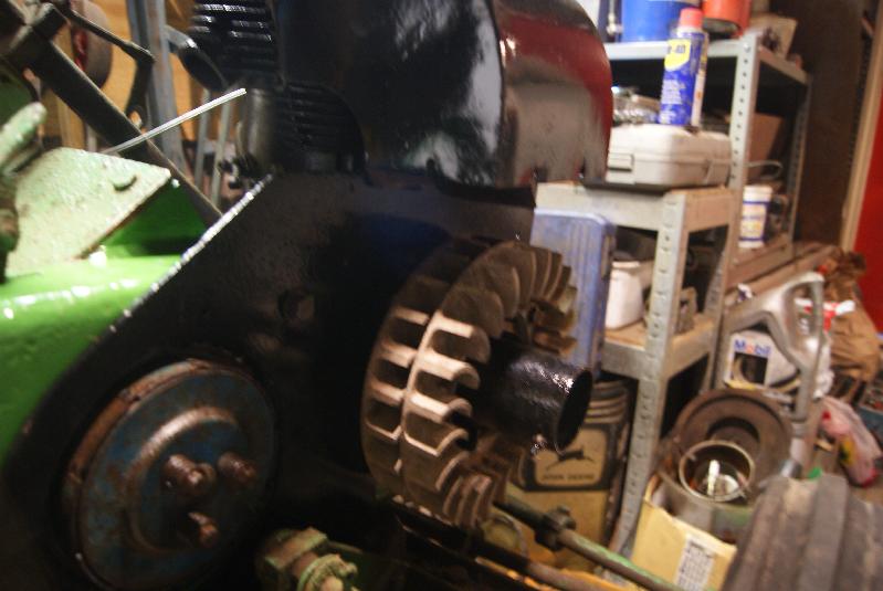
The other photo’s show the completed engine and gearbox assembly with the sprockets lined up ready for the primary drive chain and also the other side of the engine with the timing cover fitted.
Nearly there!Attachments:
May 2, 2015 at 5:12 pm #12843trusty220KeymasterIt’s about time we had a page on the “Survivors” tab for Jalo, isn’t it Ivan? (hint, hint)
We hope you have a good turnout at Navenby on Monday. I know Steve puts quite a bit of work into it.April 29, 2015 at 7:43 pm #12787trusty220KeymasterI had another thought today about how to tackle you difficult cowling repair. Once it is straightened out to your liking you could cut some strengthening strips and bend them to the interior angles of the cowling so that they run along the cracks. You could then spot weld them to the cowling (less heat, no distortion), hiding them inside.
You could then finish off by either brazing together or just filling with body filler.
Best of luck.April 29, 2015 at 7:33 pm #12784trusty220KeymasterNow that that’s done I can get on and sort the gearbox and clutch out. If you recall I had found the clutch seized solid and so I needed to get at the actuating rods that are fitted inside the hollow mainshaft.
To access these rods it is best to dig down into the clutch until you expose the end of the rod, normally with a large round foot on it, then try to pour some sort of lubrication down the rod and work it back and forth until you can withdraw the rods. It is best then to clean them up, re-oil them and re-assemble.
As you can see from the photo the clutch rod is in three parts on this gearbox and I managed to get it out without too much bother.Attachments:
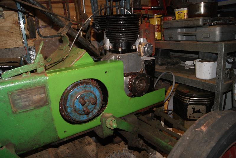
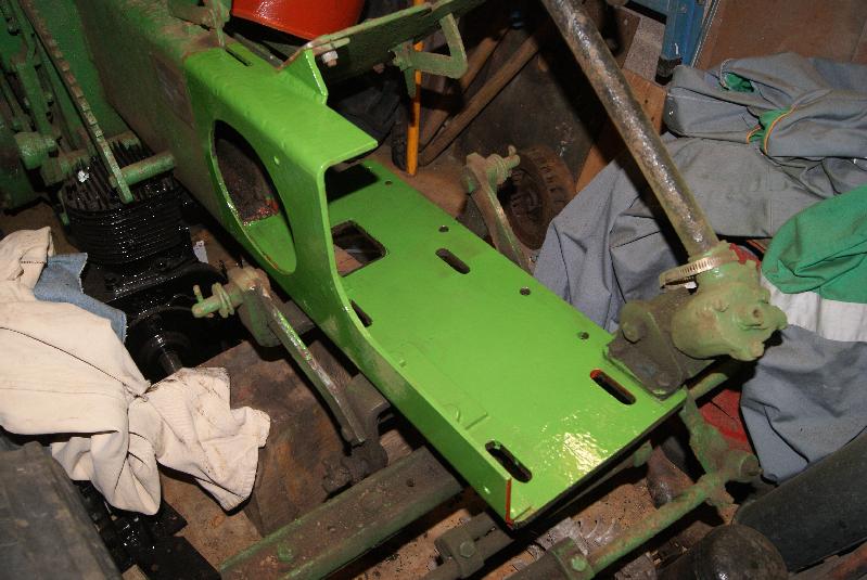
April 29, 2015 at 7:25 pm #12781trusty220KeymasterGetting back to mechanical things, it struck me that the tractor is looking a little scruffy and somebody may want to tidy it up. Because the engine is very much built in to the tractor, anybody wanting to repaint the tractor would have to undo all of the work that I’m doing, so I cleaned up the area around the engine and gearbox and painted it ready to receive the rebuilt engine.
That way it can all stay bolted together without needing to be disturbed.Attachments:
April 29, 2015 at 7:13 pm #12780trusty220KeymasterThey work very well behind the two wheeled Trusty. If you don’t have a set of these they are a real “must have” attachment for working weekends or just messing about.
April 27, 2015 at 6:40 pm #12763trusty220KeymasterThe cover doesn’t look too bad from your photo’s. Once it’s straightened up you should be able to braze the cracks and hide a strengthening strip behind.
Either way you have nothing to lose by trying.
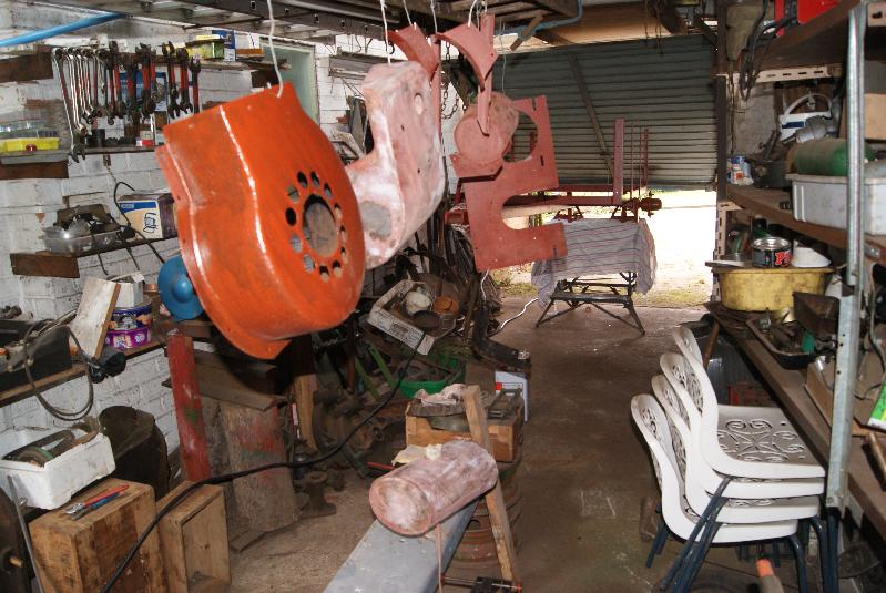
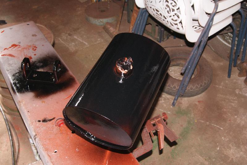
Best of luck with it.April 26, 2015 at 3:10 pm #12749trusty220KeymasterA good day today! Blew all of the loose dust out of dad’s workshop/garage and set it up as a spray booth for the tinwork off the Norton and the chassis off the Trusty trailer.
Two coats of red oxide and two coats of gloss black should be enough, leaving me a little bit in the tin to touch in bolt heads etc. once it’s assembled.Attachments:
April 25, 2015 at 5:34 pm #12732trusty220KeymasterI’ve just had a day filling and priming, filling and priming and now I’m bored! I even wore out my sander and had to buy another, but it’s much better than my old one so I’m quite pleased with it.
Tomorrow will be the day when it all starts to look good (I hope); I will spray the final coats in Dad’s old workshop where I can have a little more room and leave them to dry for a day or two before I move them.
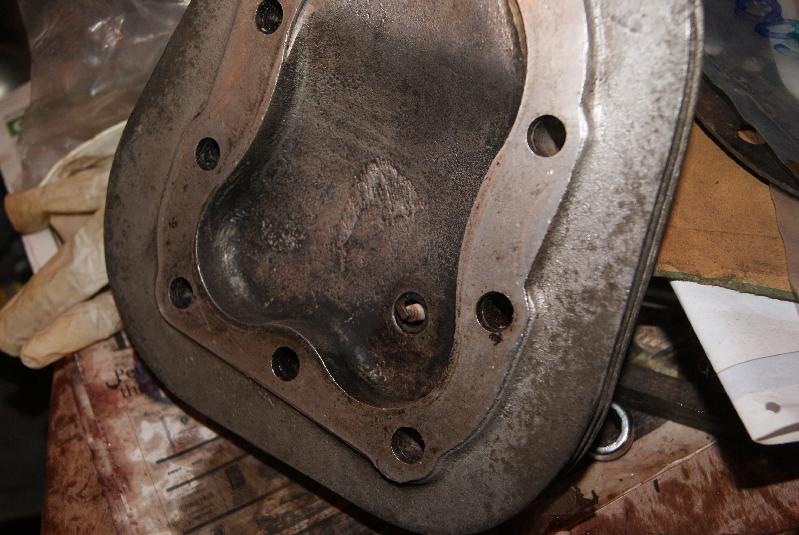
In the meantime I have now cleaned up the gearbox and side plate. It looks like the clutch rod is seized up, so that will be an interesting job one night next week. The clutch fork is situated on the left hand side of the gearbox and works a rod that passes through the centre of the hollow mainshaft to push the clutch plates apart on the right hand side. Very clever and compact but a nightmare when rusted up. Watch this space.
In the meantime here are a few more pics of the panels as they are coming together.Attachments:
-
AuthorPosts