Home › Forums › The Main Forum Area › Projects › Trusty Steed engine rebuild
- This topic has 63 replies, 9 voices, and was last updated 10 years, 11 months ago by
 trusty220.
-
AuthorPosts
-
January 25, 2015 at 1:48 pm #11518
 trusty220Keymaster
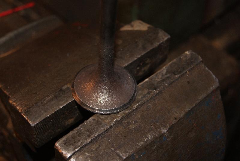
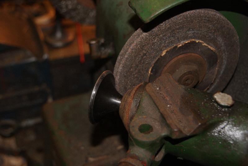
I’ve been after a valve re-facing grinder for some time now, so I used this rebuild as an excuse to bite the bullet and buy one. You can see from the photo’s what it does.
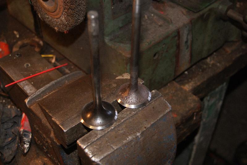
The old valve shown is the exhaust valve and it’s very badly pitted just about everywhere. A few minutes on the grinder and it resembles a usable valve again; don’t get me wrong, if it was going into a high speed engine then it would be scrapped, but as this is such a low-speed application with low power requirements then I thought it justified to re-use the old one. You can see the difference once the two valves have been finished- next job is to cut them into the seats, and I don’t have any re-cutting tools. I will try to use the new face of the valve to cut the seat with coarse paste, so watch this space!Attachments:
January 25, 2015 at 11:28 pm #11523 wristpinParticipant
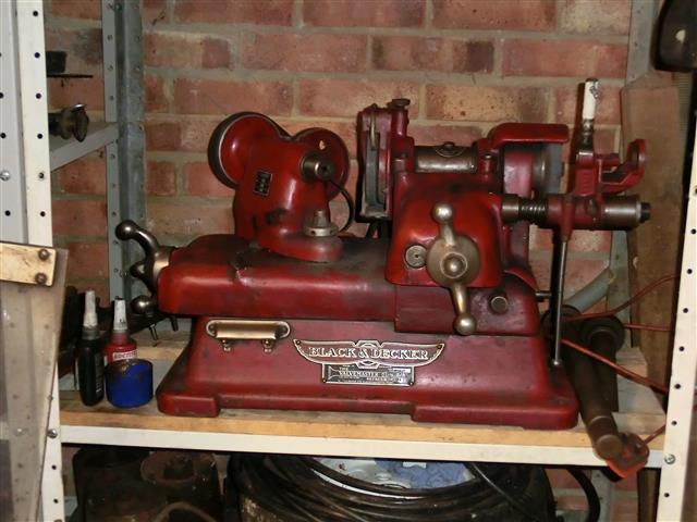
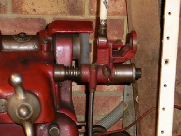
Having the right kit to re-face valves and re-cut seats “in house” is a great asset. My old Black and Decker must be 70 + years old but has repaid its £25 purchase price ,35 years ago, time and time again. It has the optional vernier valve stem grinder for valves adjusted in that way which is great for accurate setting. Fortunately having “been in the business” I have a set of Nu-way cutters for the seats.
I would advise a little caution in using one of your newly refaced valves to attempt to recover a bad seat – tends to make a mess of both. If you can’t beg or borrow a seat cutter at least use a dummy/scrap valve to dress the seat.Attachments:
January 27, 2015 at 7:09 pm #11540trusty220KeymasterThanks for that, Angus, I was of the same mind myself. Luckily one of my friends has a set of Nu-Way cutters that he is willing to lend me, so problem solved.
I’m in the trade myself, but whereas we used to rebuild engines in the 80’s when I was still in the workshop, these days it is more economic to replace an engine rather than repair it; it does go against the grain a bit, but when someone like Kubota can supply a new 4-cylinder diesel engine for a little over £3k (and it comes with a 12 month guarantee) then there is no point in repairing an old one at today’s labour rates because it comes out at about the same price and you are left to stand the warranty.
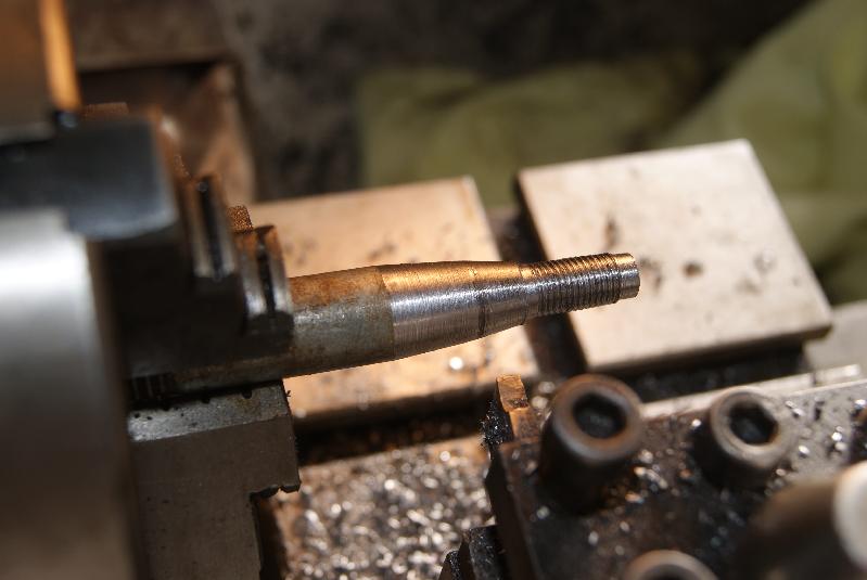
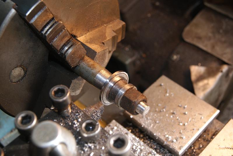
I’ve gone off track a bit, but the reason I mention it is because we don’t have anything like valve seat cutters sitting on the shelf any more. They are regarded as an unnecessary expense these days- have you seen how much they are asking for a set? Over £400 for a simple set! Daylight robbery!February 8, 2015 at 6:06 pm #11622trusty220KeymasterI’ve been having trouble with finding valve caps and springs for this engine. If it were a little newer then it would present no problems, but the design goes back to the 1920’s and apparently the more modern Nortons were two-cylinder. I’ve found a very helpful chap at Norvil Motorcycles in Burntwood who did a bit of spadework and came up with some numbers; apparently the same valves are fitted to a more modern machine so the inner tapered hole for the collets would be the same, but the outer seating where the spring sits was much bigger. I decided to buy two (at £19 each!) because I really didn’t have any choice, then turned up a tapered mandrel on the lathe to hold them with so that I could turn them down to size.
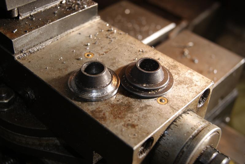
You can see from the pictures how I did it, it’s just a shame that I didn’t have a shiney new nut to put on the mandrel.
I now have two valve spring caps, I have a set of valve seat cutters on loan (that I left at work!) so all I need now is a valve spring and the job’s a good ‘un.Attachments:
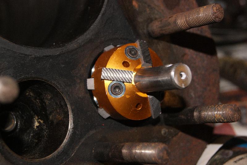
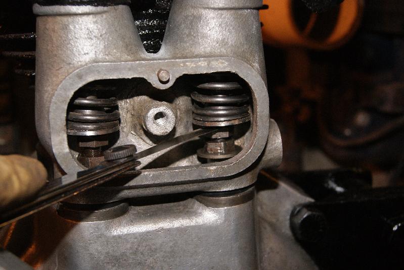
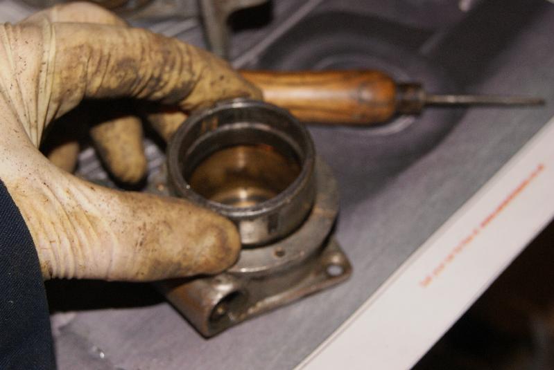
February 11, 2015 at 7:26 pm #11643trusty220KeymasterI’ve just been playing with the valve seat cutters and I’m impressed! It took me less than ten minutes to re-cut the seatings with minimal effort- but then, the set of cutters is priced at over £600 so I should have expected something good, I suppose!
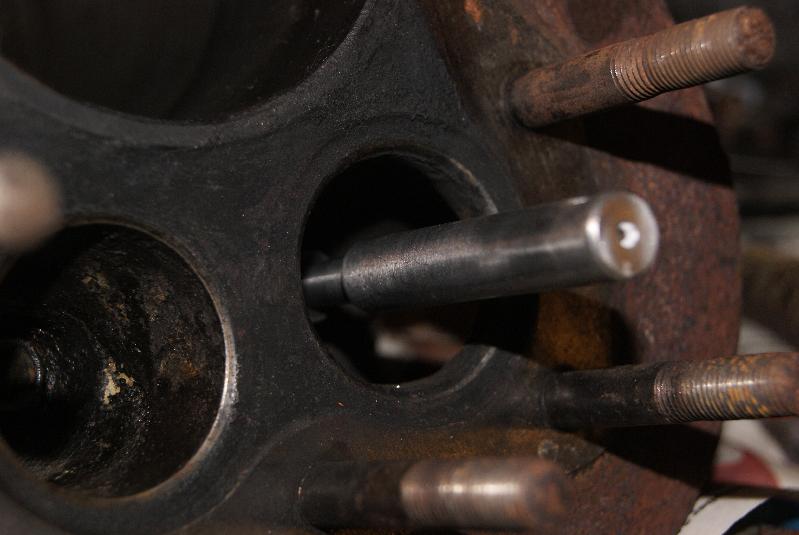
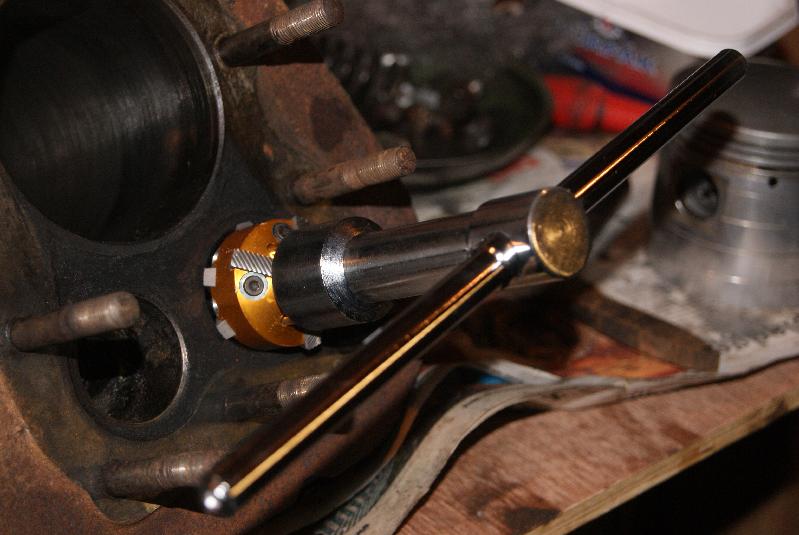
If you follow the pictures you will see that the first step is to insert the valve guide follower; this is tapered with a split plastic sleeve on the outside, so you push it in as far as it will go and it expands to fill the hole. What it does is it provides a perfectly central shaft for the cutter head to rotate on, which you can see in the next picture. All you have to do then is attach the T-bar to turn it with and cut some valve seats- simples!
Well, not quite that simple because I had to cut the seats back quite a way to remove the pits and blemishes, so the seating face was quite wide (about 3mm). This is too wide so I reduced the face to 1mm width by putting a more acute angle in the base; the correct angle for the face is 45 degrees, and I took more out underneath the face using a 60 degree cutter.
Next stage is to lap them in using valve paste.Attachments:
March 1, 2015 at 5:50 pm #11922trusty220KeymasterIt’s been a long two weeks- I’ve mainly been occupied repairing the wife’s Mondeo. First it was the dual mass flywheel so we fitted it with a single mass flywheel conversion kit and new clutch, found a hole in the gearbox where the planet gears from the diff were trying to escape, so that meant a new gearbox. Whilst doing that we found a broken front spring, so changed that but in the process found that the top bearing had disintegrated. Because it was a Sunday afternoon I had to do a temporary fix and buy a new one in the week, then do the whole spring job again to replace the bearing. I’m just waiting for the next thing to go wrong now!
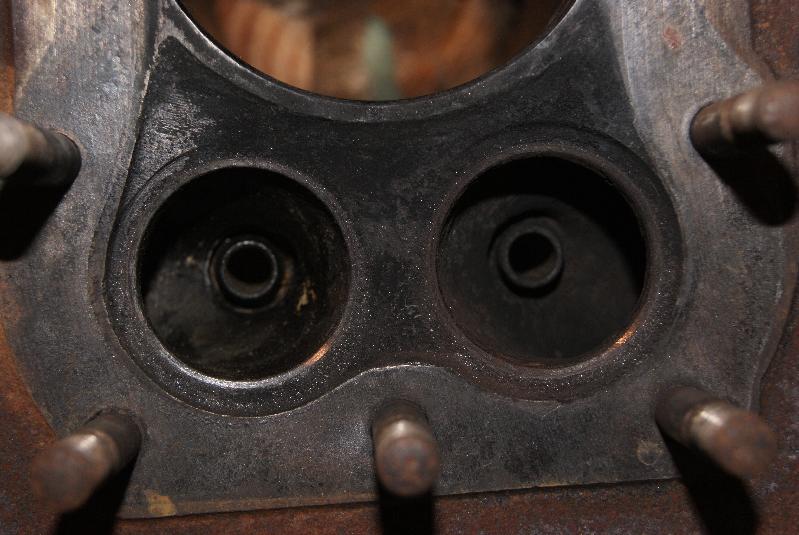
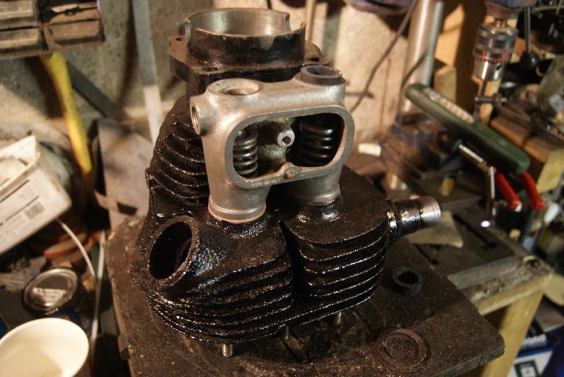
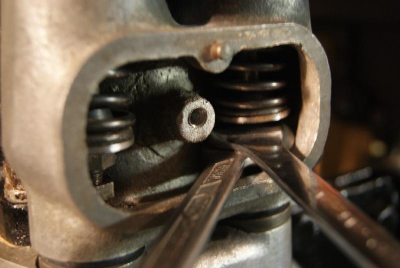
Back to the Norton; I lapped in the valves to their respective seats, making sure that there was an even grey mark all the way around both valve face and seat. Springs and colletts were then re-fitted and the fibre washers for the top seal of the valve chest were fitted. As bought they were too small for the inside diameter and so I had to open them out with a half-round file, but a little bit of care got them fitting just right.
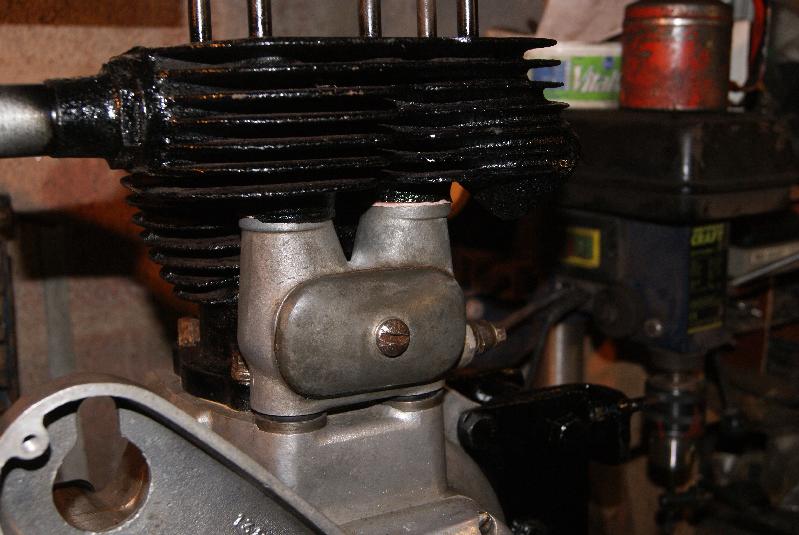
A quick trial fitting of the valve chest on the barrel was worth doing for peace of mind, and I also tried the casting on the crankcase with the rubber seals in place. Now, when you assemble it all you have to do it in a certain order because the exhaust valve follower has a washer underneath the adjusting screws- this is there so the exhaust valve lifter has something to lift up- and the washer will not fit through the bottom hole of the valve chest casting.
The only way to assemble it is to fit the adjuster screws to the inlet cam follower, lower the valve chest casting over the cam followers then fit the adjuster screw and washer to the exhaust cam follower through the inspection hole. You can see this on the photograph.
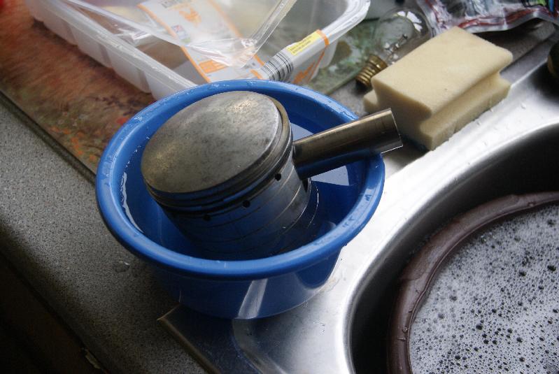
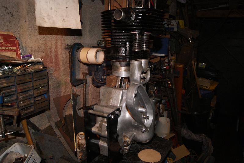
The piston rings were then added to the cleaned-up piston and the piston fitted to the connecting rod. This sounds easy and it is, but don’t be tempted to use any force in putting the gudgeon pin back in; because the expansion rates of the aluminium piston and the steel gudgeon pin are different you can heat up the piston in boiling water and the gudgeon pin will push in by hand easily, whereas at room temperature they will not be persuaded.
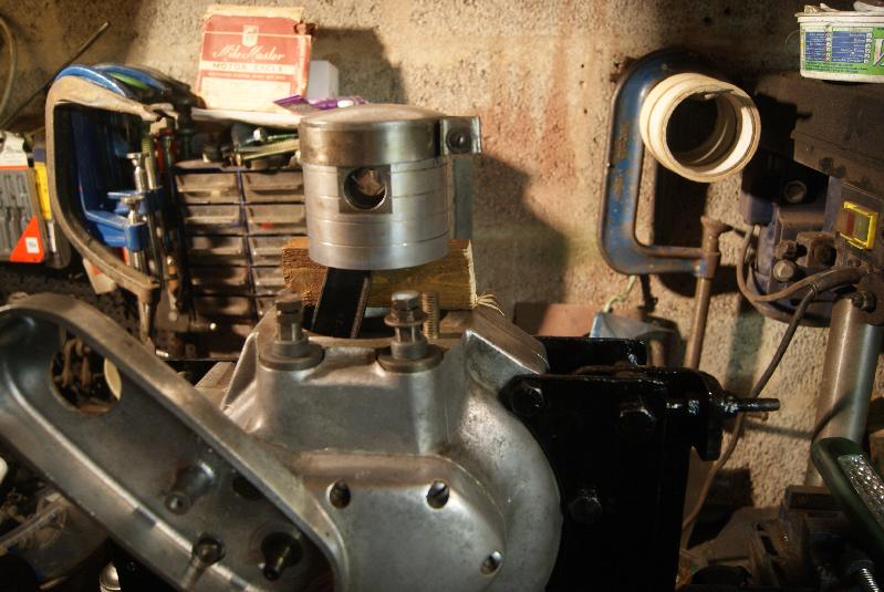
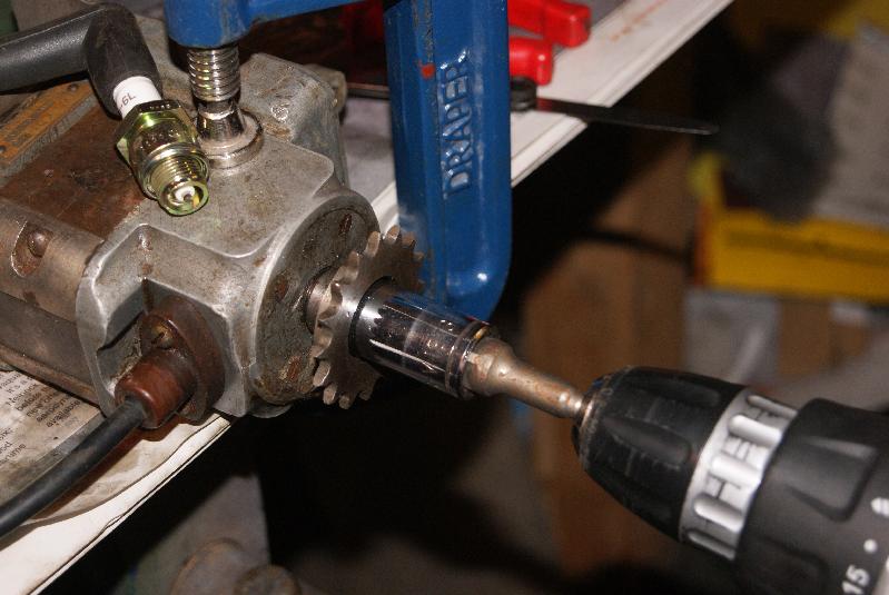
All that is left to do then is to fit a simple piston ring compressor, support the piston on a block of wood (as in the photo) and lower the barrel onto the piston whilst feeding the valve springs into the valve chest. Once the rings are in the bore you then have to dismantle the piston ring compressor to remove it out of the side, then push the barrel all the way down onto the crankcase studs.Attachments:
March 29, 2015 at 6:15 pm #12320trusty220KeymasterIf you’ve been following this and were wondering what had happened lately I can tell you that Tractor World at Malvern got in the way and so did the AGM on the following weekend. I’m back on it now so it should be quite straightforward for the next few bits.
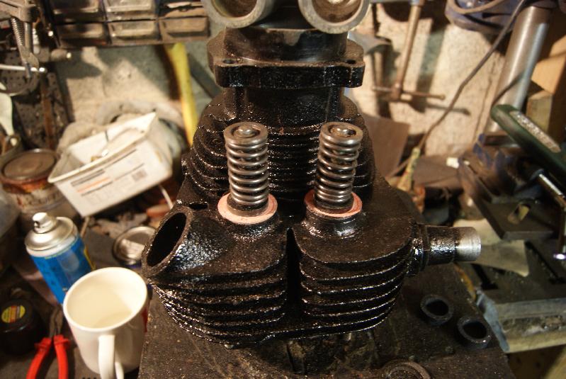
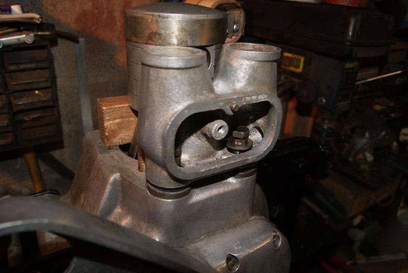
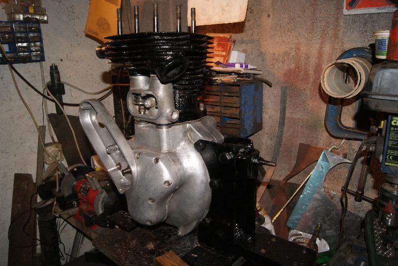
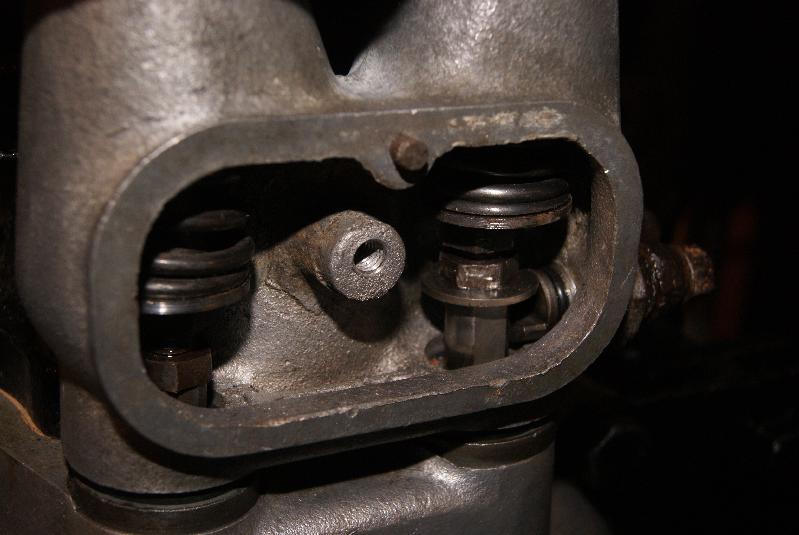
First off was to set the tappets; this is done in exactly the same way on whatever engine you’re working on. Set the piston to TDC on the power stroke (that’s when both valves are down and the piston is at the top). Do not confuse it with the stroke between Exhaust and Intake because both valves could be closed then as well, but the exhaust will only have just closed and the intake is about to open and so they will be on the wrong parts of the camshafts. Settings for this engine are :- Inlet 4 thou’ : Exhaust 6 thou’
To achieve these settings you have to screw the bolt in the top of each cam follower and then lock it using the locking nut underneath. You can see this on one of the photo’s, and it does get a little tight in there. Once you’ve locked it up do a final check of the valve gaps because they can alter when you turn the locknut slightly.
Next bit is to replace the exhaust valve lifter and to do this you really need to put the exhaust valve into the open position by turning the crankshaft. Once the valve is open you can then wind the lifter mechanism in to the valve chest, making sure that the foot is underneath the washer on the cam follower as you turn the ferrule in. Once it is all the way home, check that there is still freeplay on the lever once the exhaust valve is down otherwise the valve lifter will be holding the exhaust valve open permanently and the engine won’t run.
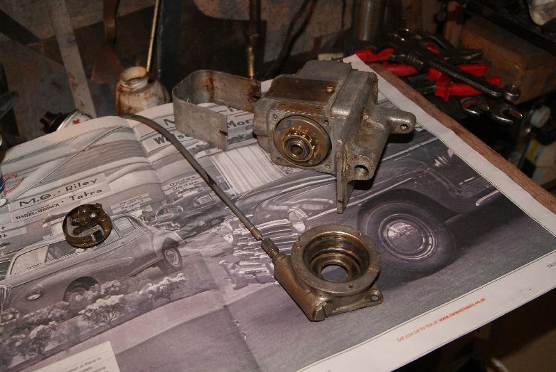
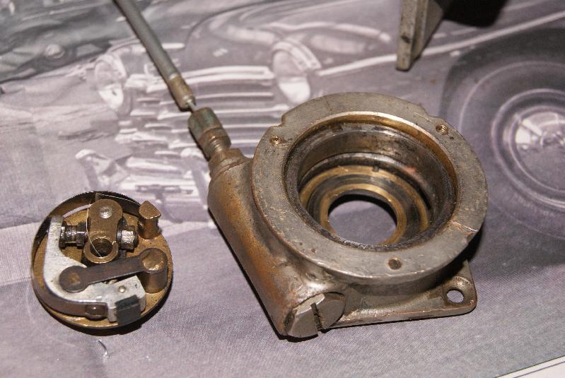
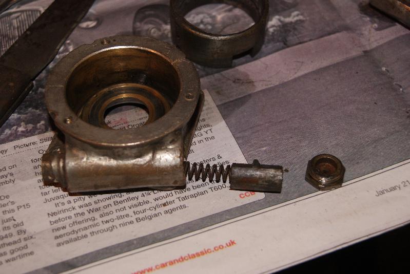
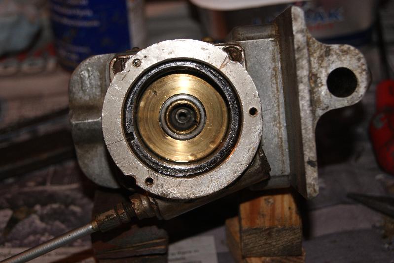
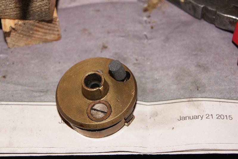
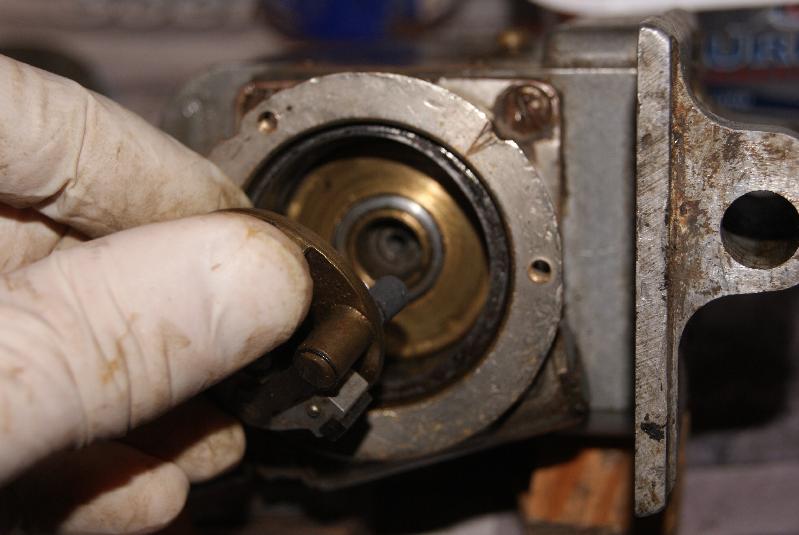
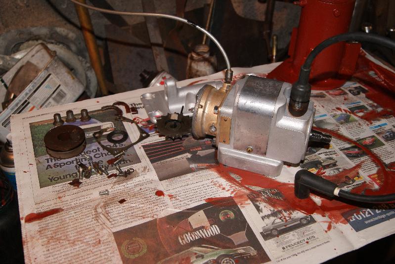
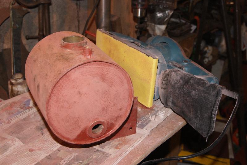
My attention was next given to the magneto which is a BTH one in this case. These are peculiar in that the contact assembly (the “points”) is on a backplate that rotates on the end of the armature shaft. The cam that operates the contact breaker is stationary and takes the form of a ring that fits inside the circular housing; to advance and retard the spark there is another device which is spring loaded that turns the cam ring slightly inside it’s housing. There is a cable control to operate this from the driver’s seat. All of these can be seen in the pictures.
What you can’t see is that the points were pitted and corroded and the carbon brush behind the rotating plate was worn away on one side; the slip ring that the brush rubs on was very dirty as well, so that I’m optimistic that with a good clean, new brush and correct gap on the points we should be in business!
Watch this space to find out.Attachments:
March 30, 2015 at 7:29 am #12340 charlieKeymaster
What is the old newspaper/magazine the magneto parts are on?
March 31, 2015 at 6:57 pm #12361trusty220KeymasterIt’s the centre pages of Classic Car Weekly- Johnny Polish lets me have his old copies. I think it’s a picture of an Earl’s Court Show from the fifties.
April 6, 2015 at 7:15 pm #12460trusty220KeymasterAs I said before, the BTH magneto is fitted with a remote advance/retard mechanism which relies on a cable control to work it. The cable was very stiff and the piston that it worked in the mag was gummed up with gunge, so a quick clean out with petrol and re-grease with LM grease sorted out the magneto end; now, what to do with the cable?
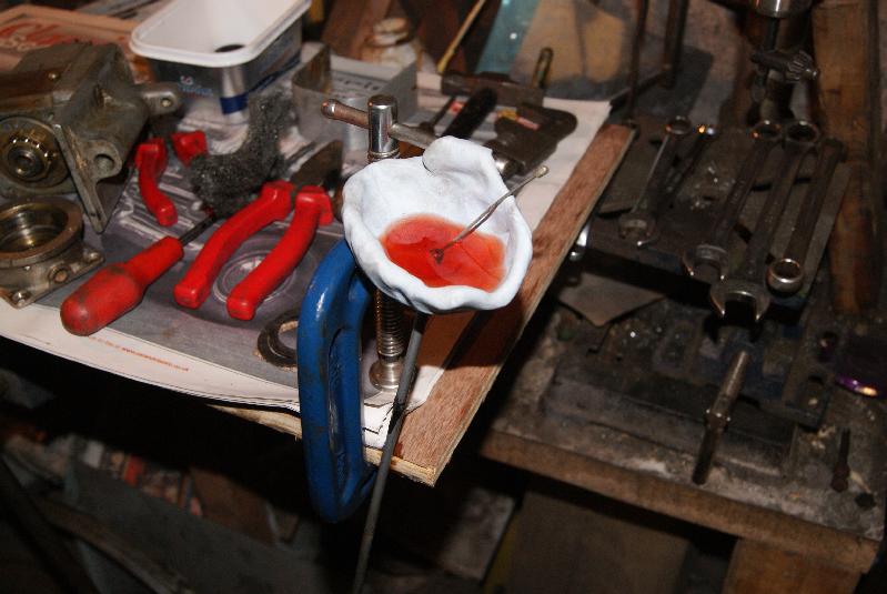
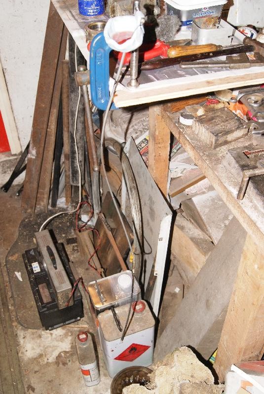
An old trick that I came across years ago when restoring my GT6 was to make a funnel out of plasticine and put the end of the cable through the base of the funnel. You then hang it up from a roof beam with the funnel at the top, fill the funnel with engine oil and leave for 24hrs.
Oh- don’t forget to put a drain tin underneath otherwise it will go all over the floor.
This method has a distinct advantage over the normal cable oilers that are available in that it uses engine oil to lubricate, whereas the cable oilers that you can buy rely on you using a can of WD40 with a straw to force oil into the cable outer. WD40 is designed to dry out in time, whereas engine oil stays where you put it and does the job for longer. My GT6 has now lasted 25 years since I rebuilt it and it’s still fine.Attachments:
April 14, 2015 at 7:06 pm #12579trusty220KeymasterWell, there’s bad news and good news about the magneto. Last Sunday I took it apart and re-assembled it three times without any success, so I spent the Sunday night looking for repairers on the internet.
The general consensus was that an average rebuild would cost £400- £500 and take 8-10 weeks. After a comment by our workshop foreman I ‘phoned up a local Villiers bike repairer; he put me in touch with a chap in Halesowen who does it for a living, so I dropped it in on Monday. I think this bloke even dreams magnetos, he talks about them constantly and is undoubtedly an expert on them.
His turn around time is 2-3 weeks and has quoted £150. I’m expecting it to go up slightly because he called me today to say that somebody has turned 60 thou off the armature and this has made the air gap so big it’s touch and go whether it would work. No wonder I couldn’t get it to spark!
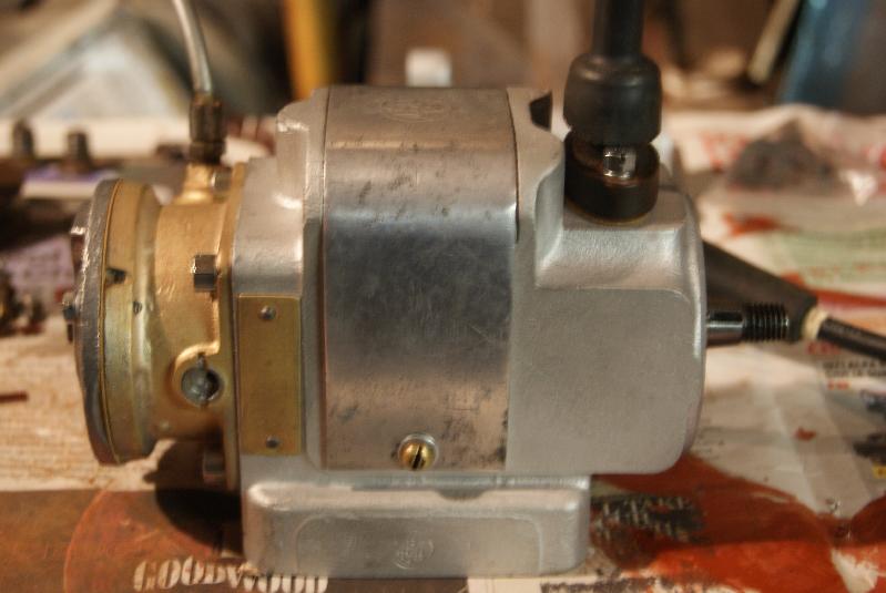
If you are looking for a magneto repairer at any time I would recommend this chap from what I’ve seen so far. His name is Tony Cooper and his ‘phone number is 0121 559 2405.April 22, 2015 at 5:34 pm #12678trusty220KeymasterFurther to the magneto repairs, I picked up the finished mag this afternoon. We spun it up on his test rig and it gave a good, bright blue spark, so then we did the very childish thing of seeing how far we could stretch it out; from the bare end of the lead we could get it to jump nearly 1/2″!!
Thoroughly impressed with his workmanship, he even let me have all of the old parts back that he had replaced. Have a look at the pictures and you can see for yourself. One week turnaround, two year guarantee and the cost of all this? £157 and a few pennies. I call that good service.
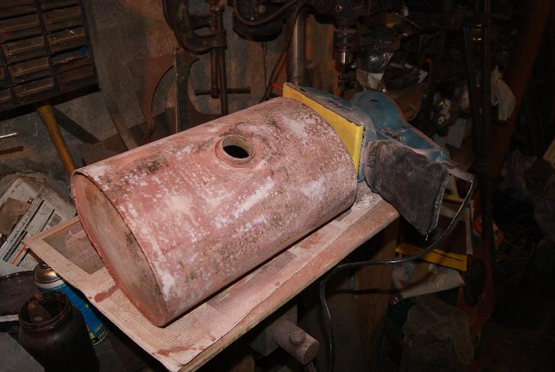
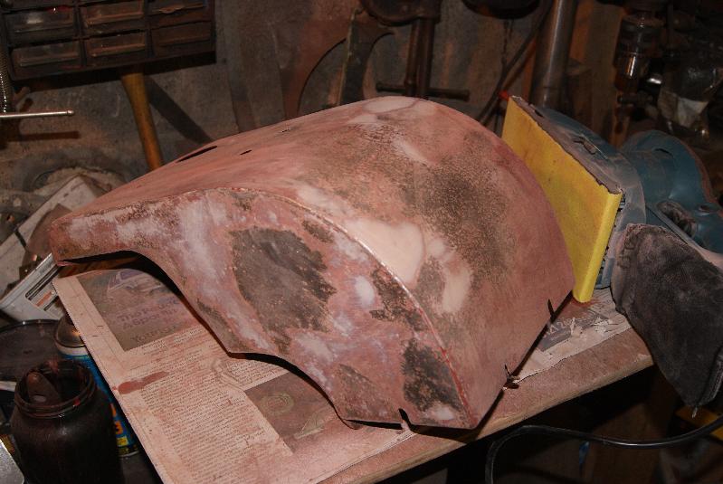
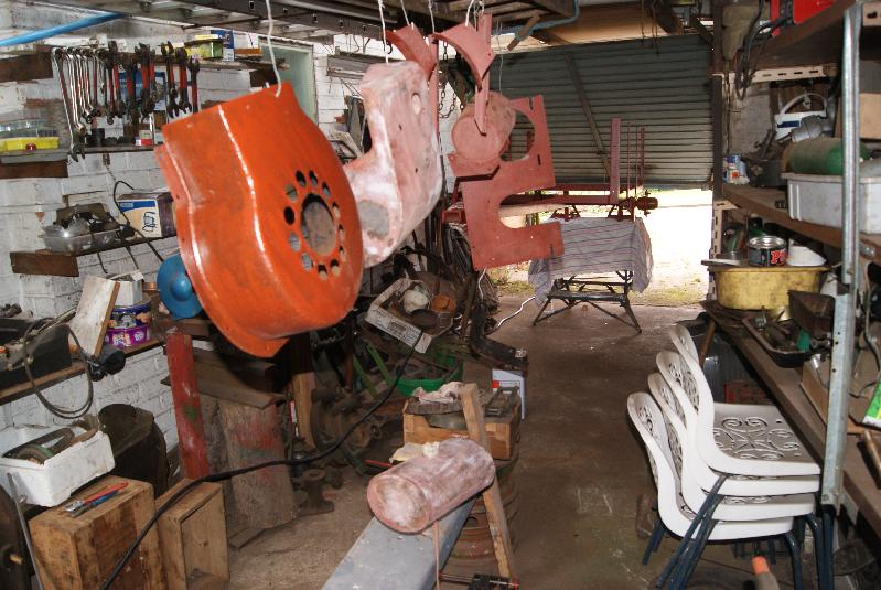
In the meantime I have stripped the layers of paint from the tinwork and started to re-finish them in primer, filling any rust pits as I go. It seems never ending at the moment but I’m getting there.Attachments:
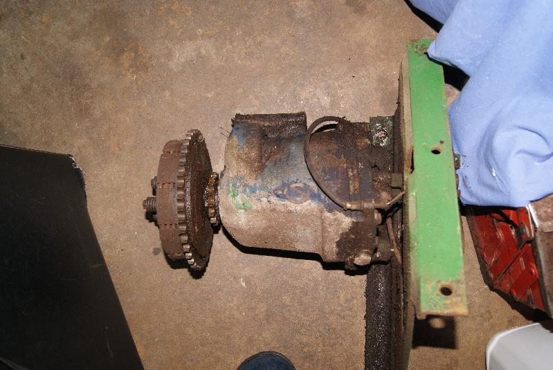
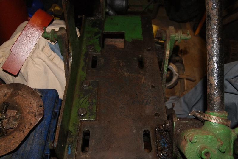
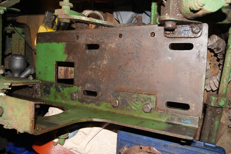
April 23, 2015 at 5:58 pm #12694trusty220KeymasterFired up with fresh enthusiasm (plus the missus was late home) I thought that I’d revise my plan of attack with the closing stages. If you remember, when I took it apart I was mainly trying to reduce it to small enough lumps to lift up and off the tractor so that I could dismantle it all further. I left the gearbox in situ resting on the rear of the engine bay because I needed to dismantle half of the engine compartment to get it out. I have now taken off the side with the steering column to make space to remove it, then cleaned all of the oily muck out of the way ready for the rebuild.
The gearbox will be taken to work for a good steam clean, then mounted back on the platform on the rear engine mount. The drive chain can then be mounted and tensioned up without having to knock my knuckles off on the surrounding footplate, then the whole assembly dropped back on the tractor.
One mystery (I think) has been solved by cleaning everything up. Originally I was undecided as to what colour this Steed had been painted because I kept finding Apple Green bits and RAF Blue/Grey as well- look on the gearbox if you don’t believe me- but it looks like it was green to start with and somebody in it’s past life has splashed a bit of blue paint around it. Probably war surplus RAF Blue/Grey by the look of it.Attachments:
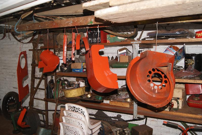
April 25, 2015 at 5:34 pm #12732trusty220KeymasterI’ve just had a day filling and priming, filling and priming and now I’m bored! I even wore out my sander and had to buy another, but it’s much better than my old one so I’m quite pleased with it.
Tomorrow will be the day when it all starts to look good (I hope); I will spray the final coats in Dad’s old workshop where I can have a little more room and leave them to dry for a day or two before I move them.
In the meantime I have now cleaned up the gearbox and side plate. It looks like the clutch rod is seized up, so that will be an interesting job one night next week. The clutch fork is situated on the left hand side of the gearbox and works a rod that passes through the centre of the hollow mainshaft to push the clutch plates apart on the right hand side. Very clever and compact but a nightmare when rusted up. Watch this space.
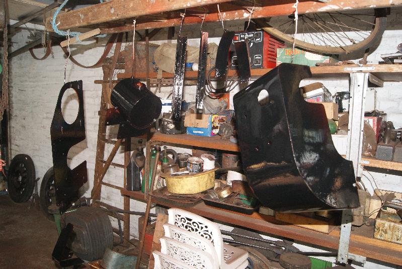
In the meantime here are a few more pics of the panels as they are coming together.Attachments:
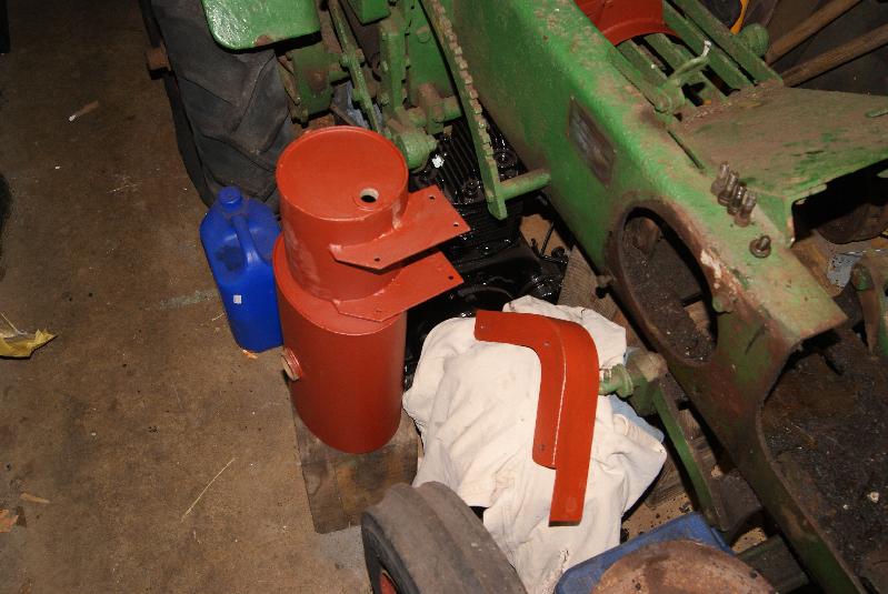
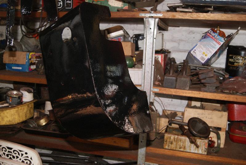
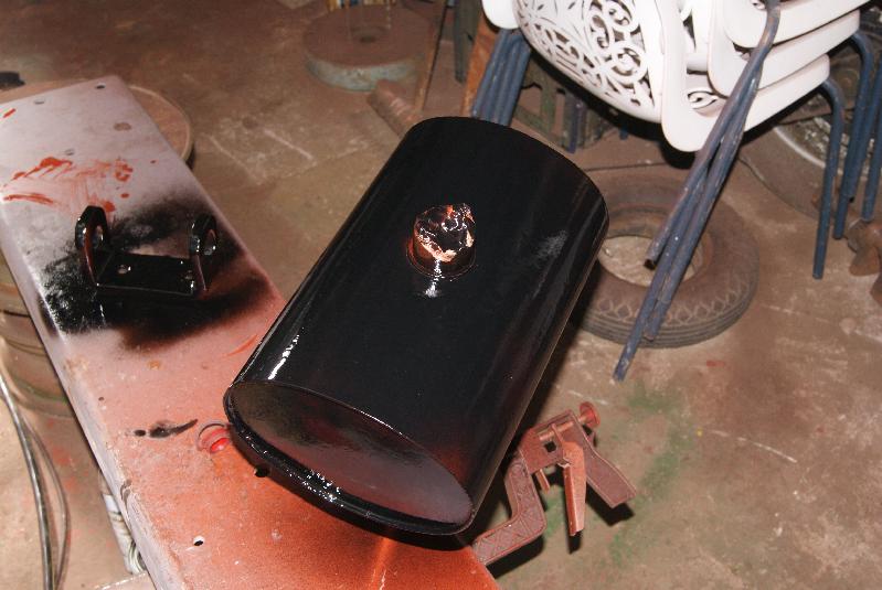
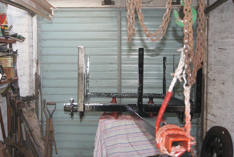
April 26, 2015 at 3:10 pm #12749trusty220KeymasterA good day today! Blew all of the loose dust out of dad’s workshop/garage and set it up as a spray booth for the tinwork off the Norton and the chassis off the Trusty trailer.
Two coats of red oxide and two coats of gloss black should be enough, leaving me a little bit in the tin to touch in bolt heads etc. once it’s assembled.Attachments:
-
AuthorPosts
- You must be logged in to reply to this topic.