Forum Replies Created
-
AuthorPosts
-
July 19, 2015 at 7:49 am #13822
 trusty220Keymaster
The styling of the bonnet front looks very FIAT to me- could it be Italian?
July 5, 2015 at 4:57 pm #13699trusty220KeymasterA nice thought. Judge for yourself from the photo’s whether you think you could make one for yourself, it’s really not difficult.
Anyway, onwards and upwards; a good day today.
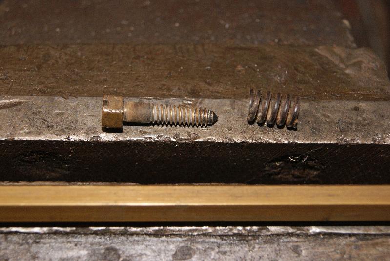
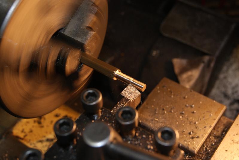
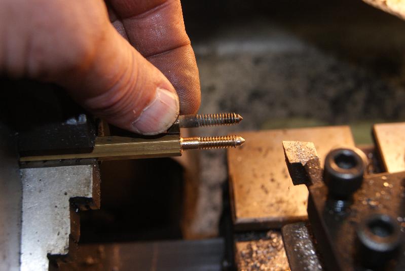
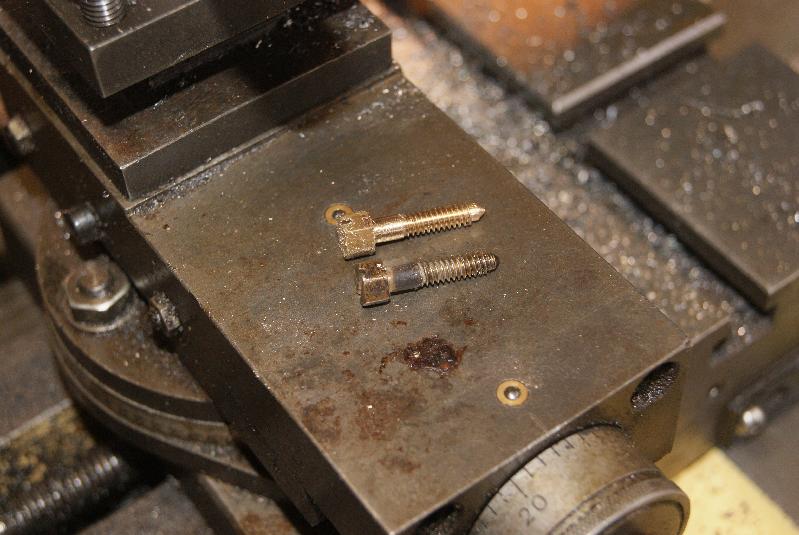
You will see the different stages of making the slow-running jet from the photo’s, but basically you start with hexagonal brass bar 5/16″ across flats. Mark off the length of thread and shank and turn it down to the external thread size- in this case the thread is 3/16″ Whitworth, so you turn it down to 3/16″ or .185″.
I chose to put the thread on by hand with a die in this case because the thread is tiny and my eyesight is non too good on the small sizes to cut it with the lathe. The result was acceptable, so to finish the end off I turned a cone onto the tip of it and relieved the thread back about 1/16″ to copy the original.
Next job was to part it off the bar, mount it in the vice and hacksaw a screwdriver slot in the head then file it up to remove the burrs. An old spring from a Zenith carb that I had on the shelf completed the job. I hope it works!
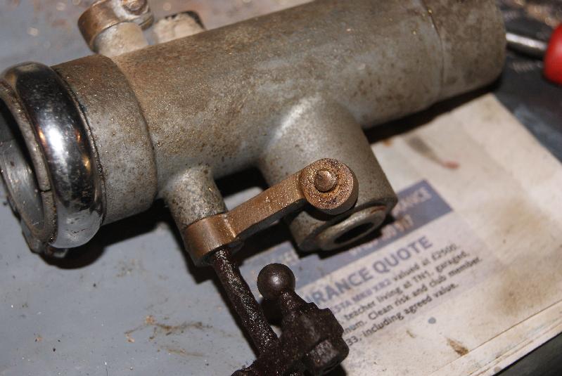
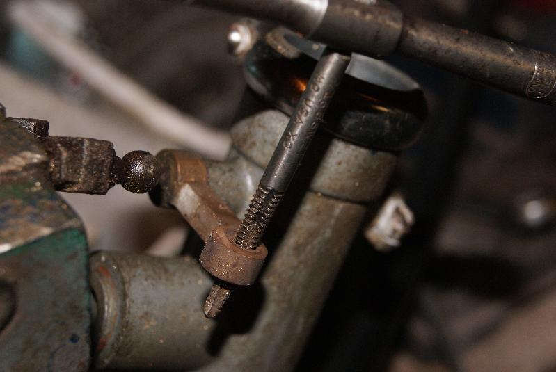
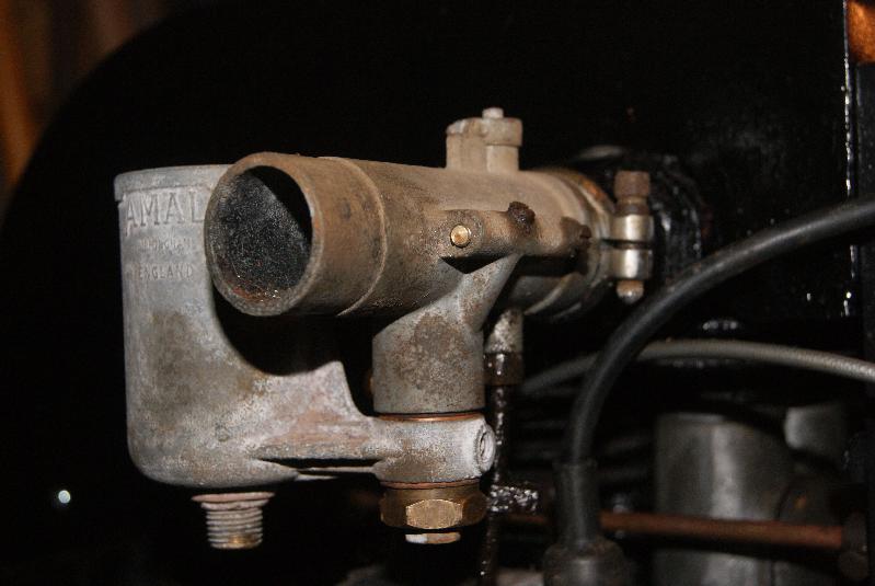
The next item on the list was the slow-running adjuster screw which somebody had twisted off some time in the dim past. It is situated on a long arm and sits against the vertical barrel that houses the main jet. When in use it is a fine adjustment to alter the angle of the butterfly in the venturi and you can’t set an even tick-over without it.
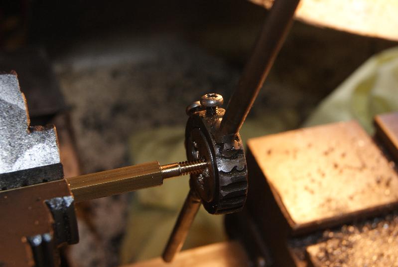
First part was to mount it securely in a drill vice, then centre-punch it and drill it using the same method as before; using progressively larger drills I was able to open it out to 1/8″, then tap it to 3/16″ Whitworth again. I found a screw in the spares box, pinched another spring off the Zenith and the job’s done!
Re-assembly of the carb was quite straightforward using new fibre washers all round, but don’t forget to take a look at the cork seal in the base of the main jet holder. It is held in place by a gland nut that compresses it when the nut is tightened; if you forget it (or lose it like I nearly did) then the carb will drip constantly from the main jet adjusting screw, so it’s quite an important little bit of wood.
Both screws were set to 1 1/2 turns out as an initial setting; these will be adjusted once the engine is running.Attachments:
July 3, 2015 at 3:23 pm #13667trusty220KeymasterThanks for the info. I was aware that you can get longer drill bits but I didn’t trust myself with such a small diameter drill being unsupported for such a length, and I took the route shown in the pictures because I was less likely to break the drill bit off in the work if it was short and supported close up to the workpiece.
As with all of these jobs, there’s always a hundred ways to do them.
I’ve just bought a 12″ length of 5/16″ hexagonal bar to make the new jet out of, so watch this space to see if I achieve it!July 2, 2015 at 6:53 am #13647trusty220KeymasterNo such luck. I’ll have to buy some!
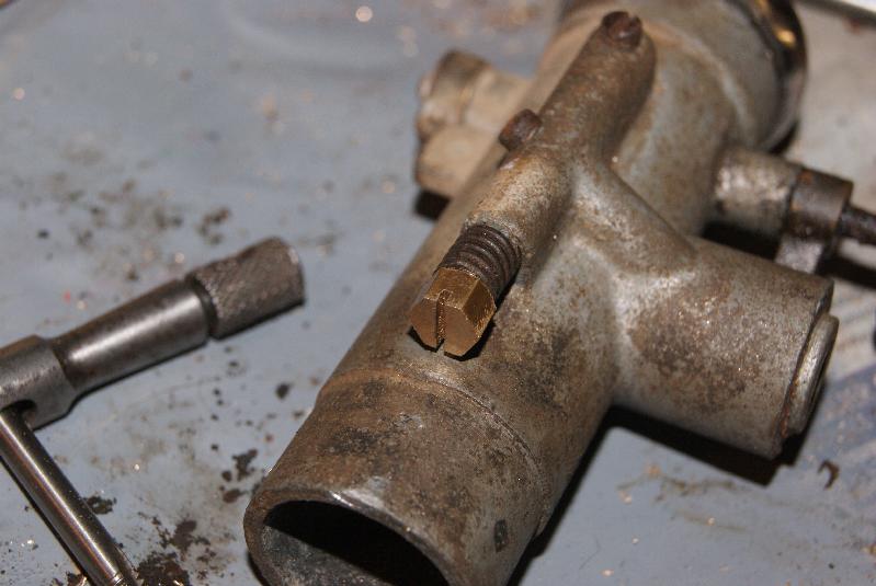
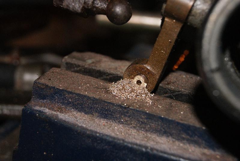
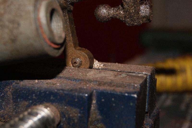
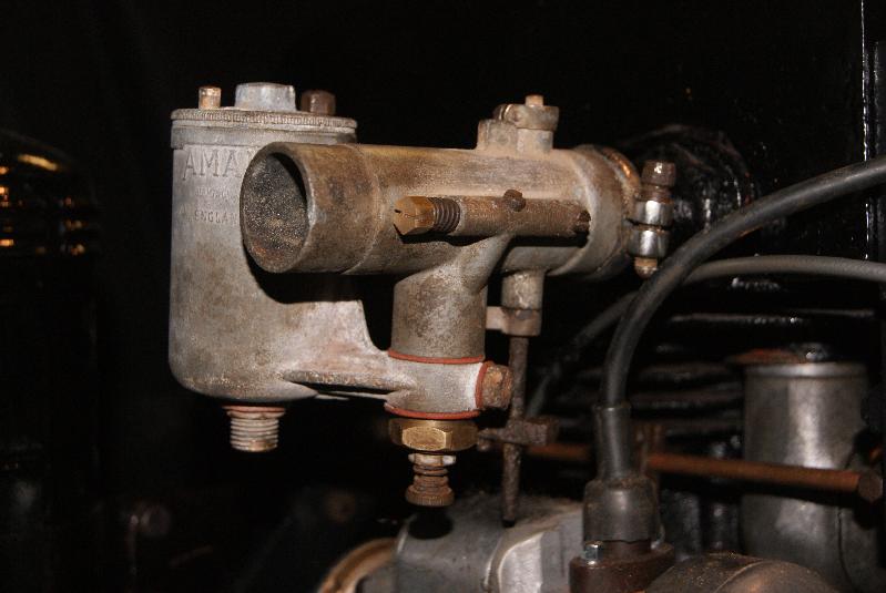
A quick update- the thread size for this jet is 3/16″ diameter with 24 threads per inch which translates to 3/16 Whitworth. I’ve got plenty of taps for this size, so full speed ahead!June 30, 2015 at 7:56 pm #13635trusty220KeymasterRemember the picture of the carburettor with a broken off slow running jet? that’s what I’ve been up to tonight. It’s too hot to do anything outside and the workshop is the coolest place, so I took a big breath and launched into it.
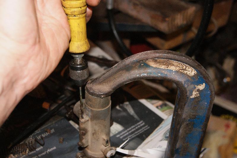
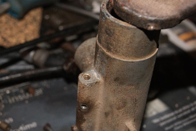
Access to it is easy enough, but it runs parallel to the main venturi pipe and so I couldn’t mount it in the pillar drill because the chuck is too bulky to get anywhere near. The solution was to use a flexible drive, very much like a scaled-down Tarpen arrangement, driven off the chuck on the pillar drill and used hand-held with some long drill bits. The much smaller chuck could just get in alongside the barrel and I took the jammed jet out in stages up to 3.5mm. You can actually see the drilled hole starting to break through to the threads in the one photo.
Next stage is to find the original size of thread and tap it out to the size, but I will have to go to my storage place to measure up my Steed to find this out.Attachments:
June 30, 2015 at 7:40 pm #13633trusty220KeymasterIf it’s up to your usual standard then it will be a tough one to beat at Newark. It’s good to see a top-notch job done on these rare items, especially as it works as well.
Well done, Alan. Keep us posted as it developsJune 29, 2015 at 2:44 pm #13619trusty220KeymasterIf it loses it’s spark when hot it may be the ignition coil breaking down internally. Of course, it could just be the spark plug or a problem with modern petrol vaporising in the pipework or in the carburettor, you can’t rule out anything.
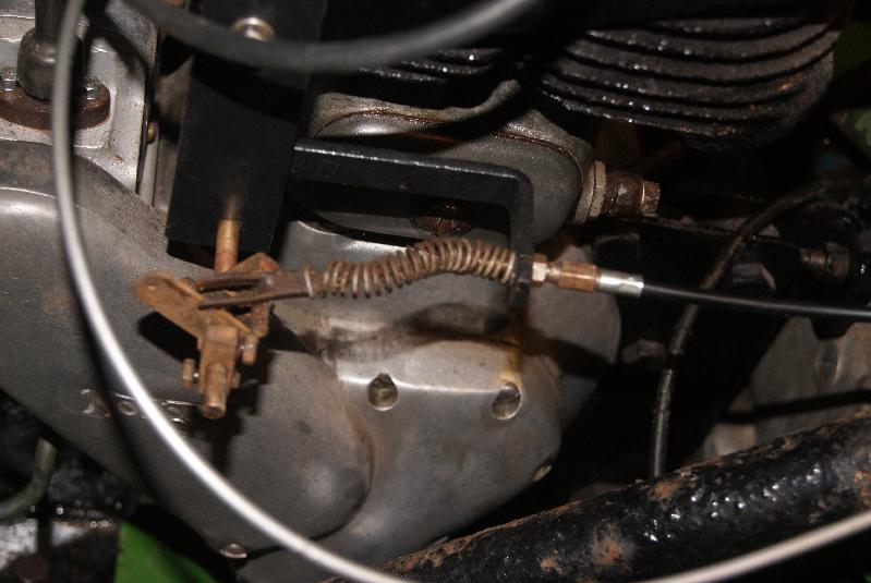
The positive side is that it looks like you’re getting somewhere with it- don’t give up now!June 27, 2015 at 2:02 pm #13578trusty220KeymasterI’m having fun today re-making throttle cables because the outers on the old ones are perished and rusty. Luckily I can re-use the inners, extracting them by unsoldering the large nipple on the one end then pulling out the cable. Fresh outers were supplied by a mate of mine who repairs domestic mowers (something we don’t do at work any more) and who has a pile of scrap cables that he keeps for this purpose. All I have to do is to thread the old inner cable into a new outer that I’ve cut to length, put a ferrule on it and re-solder the nipple back on. Sounds simple, but takes a bit of time and patience to get it right. The results make it worthwhile, though.
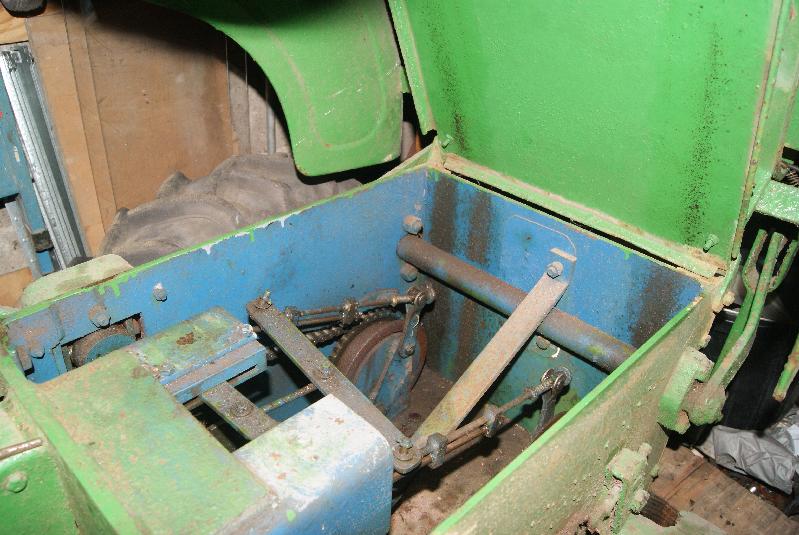
In the previous post you can see a picture of the inside of the transmission casing showing yet more of that blue paint, which looks suspiciously like RAF Blue/Grey applied over the top of the original Apple Green. I really would love to know it’s previous history, but all I can come up with was that it was sold to a machinery dealer in Northern Ireland in 1951. Did he sell it to the RAF? We may never know.June 27, 2015 at 1:51 pm #13577trusty220KeymasterYou can always go back to basics with any engine. So long as you can see the points opening and closing, you know the direction of rotation and you know when the piston is at TDC you should be able to time it up.
I’m guessing that this engine has the cam on the flywheel.
Firstly you want to loosen the flywheel, then set the crankshaft so that the piston is at TDC. Then turn the flywheel in it’s normal direction of rotation, wait for the points to close then keep turning the flywheel slowly until the points just start to open again- this is the point at which the spark is generated. If you can’t quite see when the points are opening I used to put a piece of cigarette paper between them, keeping a light pulling action on the paper whilst rotating the flywheel. As the paper is released then that is where they start to open.
As soon as you see/feel the points open, stop rotating the flywheel and tighten it onto the crankshaft trying to keep everything in position so that it doesn’t move.
This should work for any engine that has the camshaft inside the flywheel. I’ve used it countless times on Villiers engines.
You can add a little refinement if you feel confident as well. Really the spark should be generated just before TDC (ignition advanced) so you can turn the crankshaft slightly before tightening up the flywheel to give this advance; of course, if you do it too much it will fire too soon and kick back. This makes you swear and clutch your wrist!
On a small engine such as yours you should have no more than 1/4″ gap between the top of the piston and the top of it’s stroke to have an effective advance.
Best of luck!June 25, 2015 at 7:56 pm #13556trusty220KeymasterIt seems ages since I last wrote anything here, so here’s the catch-up.
As I said in the last piece, somebody in the past has done some pretty major surgery on this tractor. I’m guessing the gearbox has been replaced at some point and the new one didn’t quite fit; it’s the right one (an Albion HR3) but where the gear change linkage fits on to it’s square location there seems to be an extended piece that protrudes about 1″ out of the box, whereas the original’s was a flush fitting. To accommodate this somebody has taken a hacksaw to the side plate and taken a chunk out of it, then rebuilt it with odd nuts and bolts.
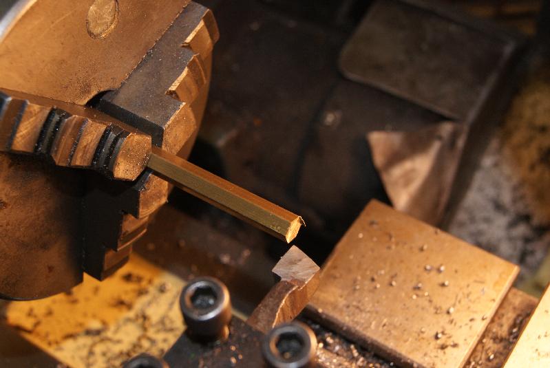
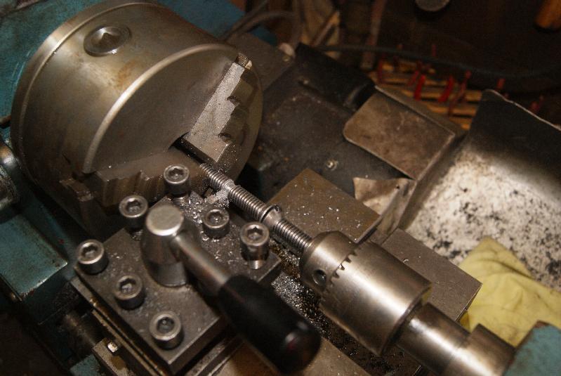
I decided to leave the surgery alone, but one thing that always annoys me is the mixture of sizes of bolts. The only way to re-assemble it was to do so with the correct bolts, so a trip to our local supplier provided me with the correct sizes and threads; besides, five of the bolts holding the footplate down were countersunk and only Whitworth countersunk heads would fit the holes- everything else had heads that were far too large. Look at the photo’s and judge for yourself at the ones I chose; I think they were the best option.
Whilst we are talking about these bolts, the only ones I could find were 3″ long and so needed shortening. The easy way is to just take a hacksaw to them, but then they would look to be different lengths and tatty, so what I did was to mark them with a hacksaw cut and then put them in the lathe as shown in the photo. The parting tool was lined up with the cut, but before it was wound into the cut I brought the tailstock in with another chuck holding another bolt to act as a length stop. In this way it was quick work to part off the first bolt, take out the remainder and replace it with another so that the heads touched; all five bolts were then cut off to exactly the same length.
Pleased with myself, I replaced the footplate and ticked off another job.
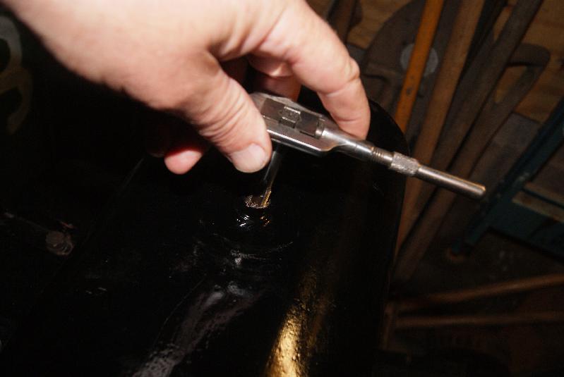
I was dying to try the fuel tank sealant after Philip Plotkin had recommended it. I tried POR15 some years ago and found that it has a short life of two to three years before it started to peel off, so SLOSH was going to be the next trial. As you can see from the pictures I took a lot of care to keep it away from the paintwork and wound a plug of paper into the outlet hole as well. Once poured in it is easy to chase around the tank inside and sets to a hard finish very similar to fibreglass resin. Even though I had put a plug of paper in the outlet hole, the resin had hardened in the thread and so I had to tap the thread out again- if you need to do this the thread size is 1/2″ BSP- but once done the tap has gone in and fits a treat. All I have to do now is to find some bolts to hold the tank straps together that are the correct size and the tank will be done.
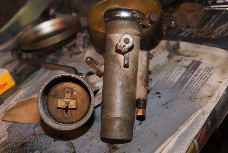
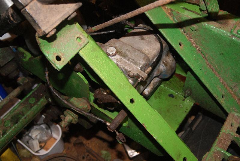
One big setback has been the carburettor; if it wasn’t so rare I would have looked for a replacement, but considering the rarity I am determined to recondition it.
The first stage was to dismantle it carefully and clean it in an ultrasonic bath. One thing that I couldn’t budge was the slow running mixture screw and so I left it there for now. You can get behind it by removing two blanking screws, so I left it to soak.
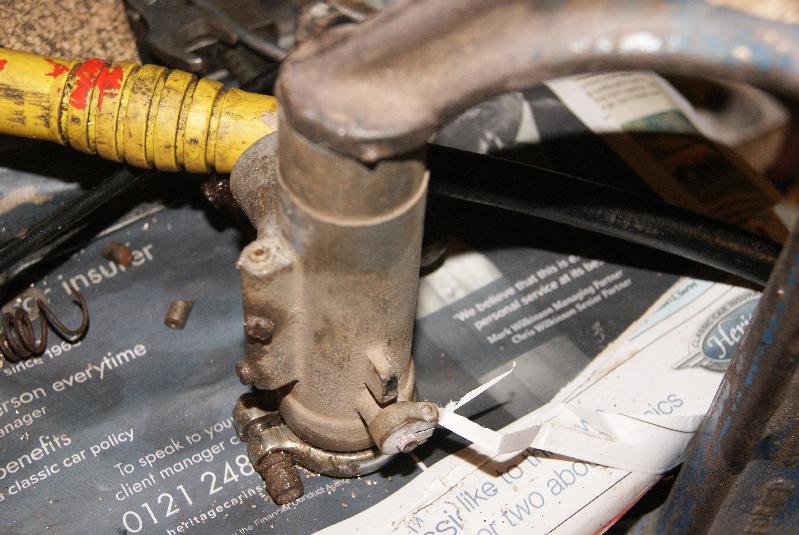
Because it is such an awkward shape putting it in the vice was out of the question; the only way to hold it firmly was to mount it onto the engine, so I did that and then tried to undo the stuck jet. The jet that is in the hole is not the correct one and so the thread is probably a mis-match; that would explain why it sheared off despite using all of my reserves of patience, skill and know-how. Damn!
I’m now going to have to borrow a Dremel power tool to try to drill it out. Wish me luck!Attachments:
June 22, 2015 at 10:14 am #13544trusty220KeymasterTake your spanners with you and you should be OK. The wheels come off, so does the seat and the axle is held on with two long bolts. If you dismantle it you would be surprised how small you can make it.
Two people can pick one up quite easily so it shouldn’t overtax your car’s suspension.
Best of luck.
GeoffJune 21, 2015 at 6:59 pm #13539trusty220KeymasterGlad to have you on board, Darren, and I hope we live up to your expectations. The club stand that we put on every year at Newark in November always features hand tools as it is a very overlooked part of our hobby.
There is a wealth of hand tools to be picked up for very little money and so it is a very good place to start your collecting; you may want to be selective and only collect certain things otherwise you may find that you get over-run very quickly!
Various themes that members have used are tools from a certain manufacturer, or different designs of spade or fork- the possibilities are endless.
Good luck with your collecting.June 17, 2015 at 4:06 pm #13523trusty220KeymasterThe problem with putting a set amount on the sponge is that you may not get an even coverage. It’s far better to put too much on then squeeze out the excess; a bit messy but you are more likely to reach all the corners. That’s the way Briggs and Stratton used to recommend back in the good old days.
The oil is there to make the sponge act like fly paper so the dust sticks to it. The oil and dust can be washed out with clean petrol and the sponge re-oiled to extend the engine’s life.June 15, 2015 at 3:59 pm #13486trusty220KeymasterYou could always try Steve Woollas’ new workshop. I’m told there are a few in there!
June 14, 2015 at 9:08 pm #13465trusty220KeymasterIt was a pleasure! It’s easier to show someone how to drive these machines than to describe it. I’m glad you enjoyed it.
-
AuthorPosts