Forum Replies Created
-
AuthorPosts
-
April 19, 2021 at 6:23 pm #37003
 wristpinParticipant
Looks like an oldish Atco heavy duty 24” which originally had a Villiers 150cc lightweight engine but has acquired a Honda engine of some sort.
April 18, 2021 at 8:26 pm #36998wristpinParticipantShould we be seeing an image?
April 18, 2021 at 6:44 pm #36993wristpinParticipantWould that be with a MAG engine ?
April 15, 2021 at 12:43 pm #36947wristpinParticipantHi all, anybody any idea of the manufacture year of this outstanding vintage Hayter?
No disrespect but it’s neither outstanding or vintage. It’s a bottom of the range 16” Harrier with the cheap engine option , correctly identified by Hillsider. Could even be the down specced version sold through the Sheds or mail order outfits.
April 3, 2021 at 8:59 pm #36912wristpinParticipantI remember the three terminal batteries but only on Atco machines. Not saying that they were never used on Webbs but we only saw them on Atcos. Some Webb machines had an on- board charger that resembled a car ignition coil of the day.
April 2, 2021 at 10:16 pm #36909wristpinParticipantApril 2, 2021 at 1:28 pm #36904wristpinParticipantHopefully the other forum contributor will supply an image of his machine – a picture saves a thousand words etc.
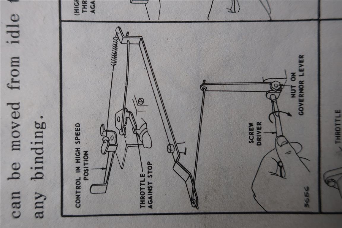
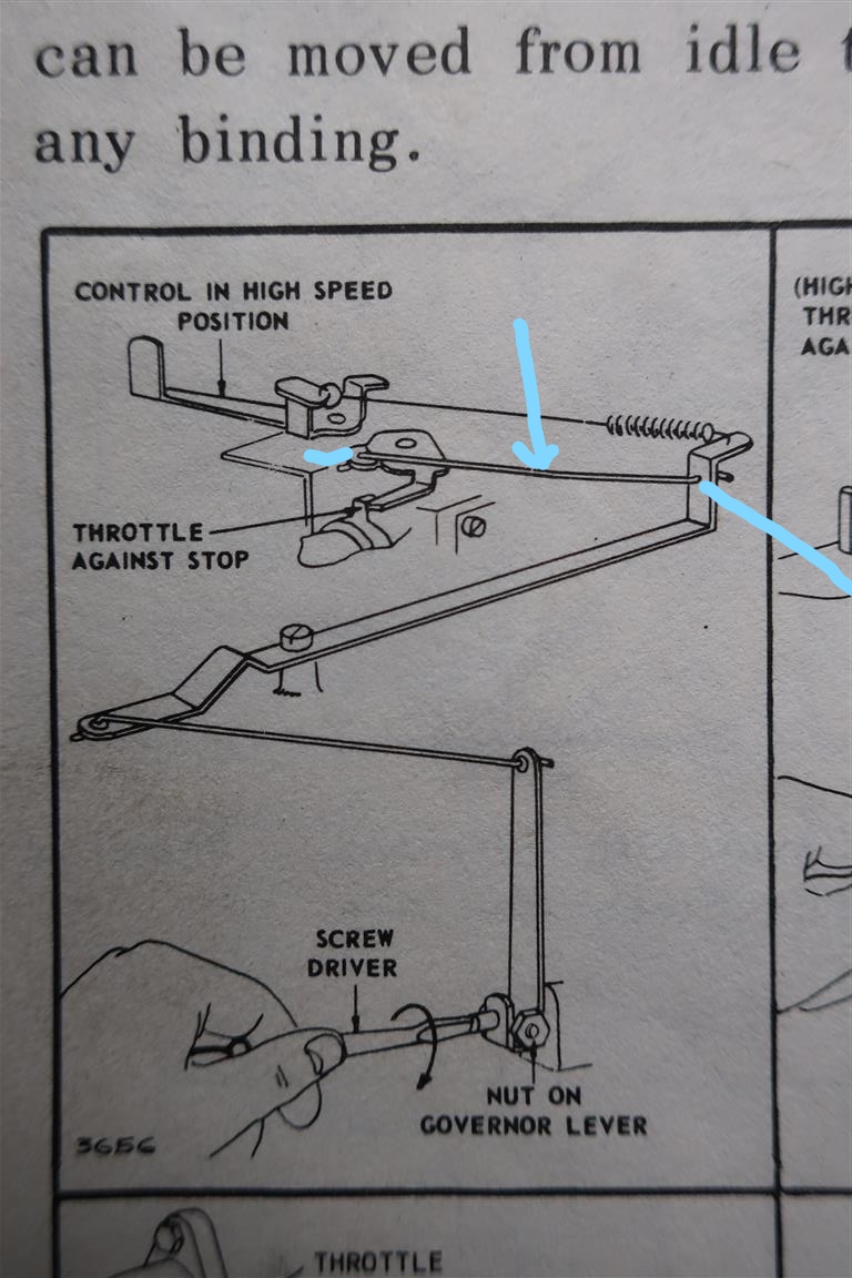
The big spring is correct at the Governor arm end and at the cable end – I think.
The rod will be correct on the vertical face of the Governor arm. On the throttle plate are both the holes the same size, or is one showing a worn or more polished bore? My thoughts are that the correct hole is the one that’s not got the small spring in it at present.
If you are going to make a new link rod it’s a matter of taking the centre to centre measurement with both the variable elements in the same state ie with the Governor arm in the fully shut position and the throttle closed ( undo the idle stop screw until the throttle butterfly is fully closed) or with the governor arm wide open and the butterfly the same. For the sake of a fiver I’d get the correct rod as it will be the right length and save the hassle of forming the cracked end or ends with the first right right angle bends at exactly the right centres.April 2, 2021 at 10:58 am #36896wristpinParticipantRight, finally got my brain into gear and found a diagram.
The big governor spring is in the correct place. Just round the corner from where it is hooked to the governor arm on the vertical bit , will be an empty hole. That’s where one end a short solid rod should go; the other end going to the throttle spindle. The thin spring probably slides up the short rod and shares its anchor holes at each end to keep the linkage taught but it will probably work ok without it. Those thin springs enclosing various rods are variously described as anti-rattle and anti-surge but are often missing or broken on older machines.
Ask your “mechanic” if he might happen to have a spare rod!
The rod is shown as still available, 260654 £4.55+vat or you could make one from a piece of piano wire. A bit of experimentation may be needed to get the length right but it shouldn’t be to difficult. The cranked ends need to be at right angles to one another.Attachments:
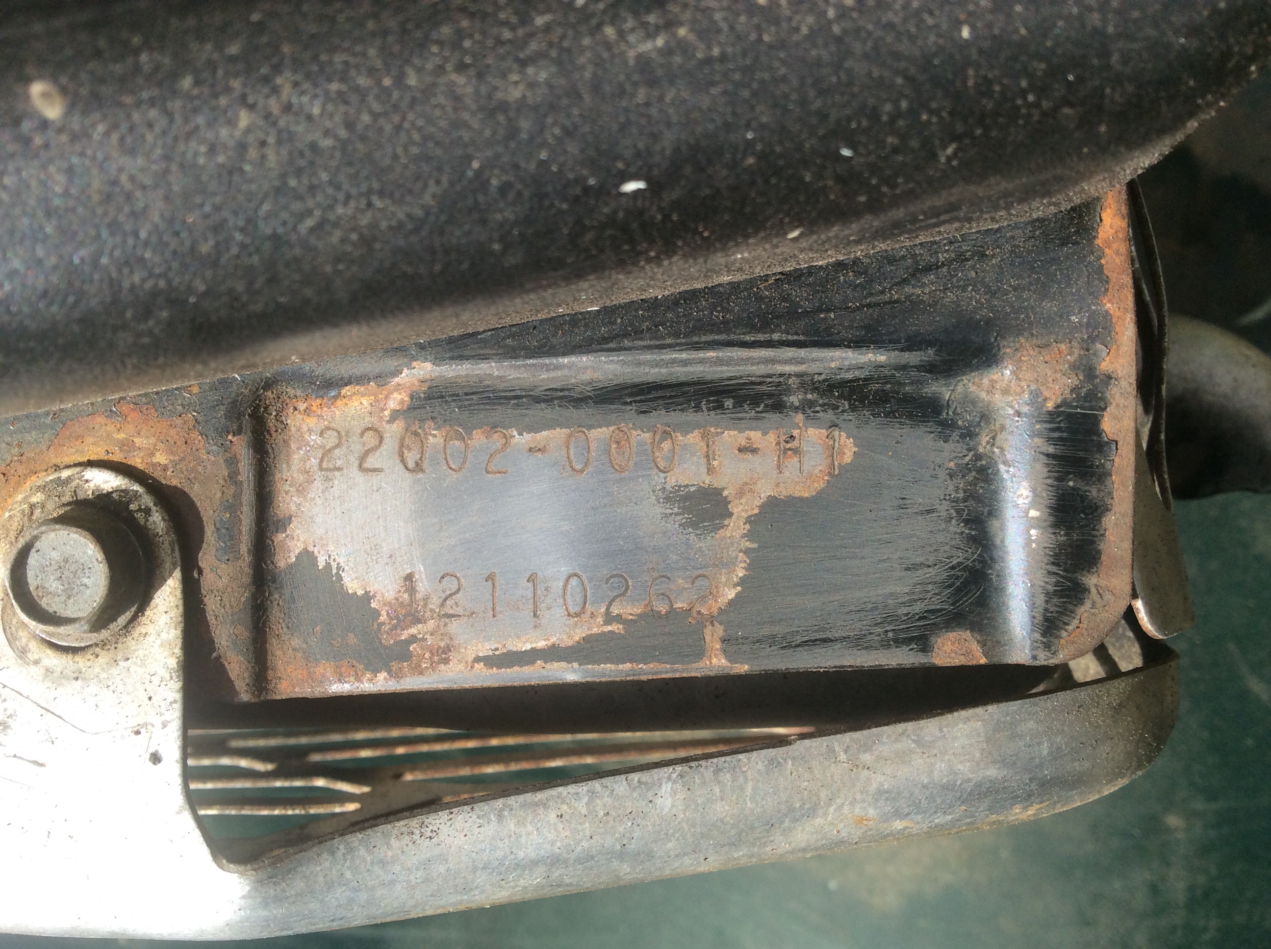
April 2, 2021 at 9:04 am #36894wristpinParticipantProblem, can’t read the MTC numbers in your post. You may need to lightly sand across them or high light them with a felt tip. Something like this. Or just post the numbers!
The rigid link will go between the horizontal arm that pokes out from under the flywheel and the plate on the top of the throttle spindle – that is the governor trying to shut the throttle The big (now overstretched) spring will be collected to the handle bar operated cable and the other end hooked to the governor / throttle spindle to oppose that closing force. What I can’t recall from memory is quite where that end should be located.
If anyone on this forum has a Hayter 21 with a 5hp Briggs, it probably has a similar set up.Attachments:
April 2, 2021 at 7:21 am #36888wristpinParticipantDefinite case of finger blight!
It appears to be missing a rigid link between the Governor arm and the throttle spindle but the perpetrator has repurposed the Governor spring to try to replace it. The small diameter spring threads over the missing link to keep the linkage in tension.
I’m struggling to find a decent schematic of how it should be, so please post the Model, Type and Code numbers that you will find stamped into the engine cowling – probably above the spark plug.
Meanwhile there’s another VHGMC member who to my knowledge has a similar cultivator and I will ping him a mail and he may be able to post an image of his machine.March 29, 2021 at 8:53 pm #36876wristpinParticipantKubota Mag did indeed produce an engine with a drive off the cam . In their case it was to give a low speed drive at tick over to operate with the centrifugal clutch on a Ransomes Mastiff without having to redesign the gearbox. The snag was that the cam runs in the opposite direction to the crank. The answer was to change the engine rotation . That aside, there’s no sign of a camshaft power take off on the OP’s engine.
The image of the “gearbox” is only marked Hi, Lo and Neutral so if that machine has a reverse it has to be achieved elsewhere, but the primary drive must be forward leaving any reverse side belt or friction system to deal with the lesser used reverse.March 28, 2021 at 11:42 am #36861wristpinParticipantNow you tell us! Time to stop the talk and post a few decent images of the mechanicals.
March 28, 2021 at 9:57 am #36853wristpinParticipantWe need a few more images to see exactly what you have as your description doesn’t match any Clearway that I’ve worked on or have manuals for. Rather than being “ pre hydrostatic “ it could well be post hydrostatic as I know it.
March 27, 2021 at 10:20 pm #36849wristpinParticipantIf your machine has a belt from the engine or drive shaft driving a pulley with a fan on the end of a large finned lump, it has hydrostatic drive which gives stepless variable ground speed in both forward and reverse . An image of the mechanicals from the operator’ s position will clarify this. The finned lump with an oil reservoir on top is the hydrostatic drive unit – commonly shortened to the hydrostat.
March 27, 2021 at 7:14 pm #36846wristpinParticipantHas it ever worked correctly in your ownership or is it a new acquisition ? If new to you , maybe there’s history . Worth checking that the “ handlebar” lever is properly set up/ located at the hydrostatic end and not slipping on the hydrostat’s selector shaft.
-
AuthorPosts