Forum Replies Created
-
AuthorPosts
-
December 5, 2020 at 4:52 pm #36105
 trusty220Keymaster
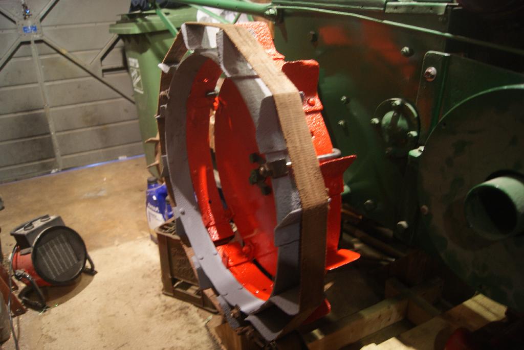
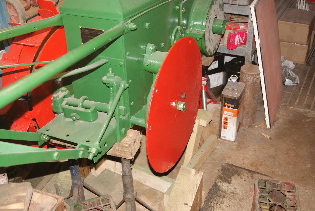
Oh dear, I’d forgotten the lessons I learnt when putting on the outer ring of the first wheel. The best advice I could give is to let someone else do it! Not having anyone else to give it to, I settled on trying to find the best match for the gaps/strakes. After half an hour of swearing I gave up and just put a clamp on the outer ring in the point furthest away from the join- if you remember, the ring is circular (sort of) but the ends are not welded together, they just float freely.
So, clamp on the middle point opposite where the join is, then feed one half of the ring onto the first row, settling it down with a rubber mallet (it hurts your fingers less), clamping it down every foot with a hook bolt and levering/swearing/hammering it until you get to the free end. I then put a ratchet strap around the outside of the strakes to pull it into some form of a circle and repeated the process. I can see why they didn’t keep this design of wheel for very long!
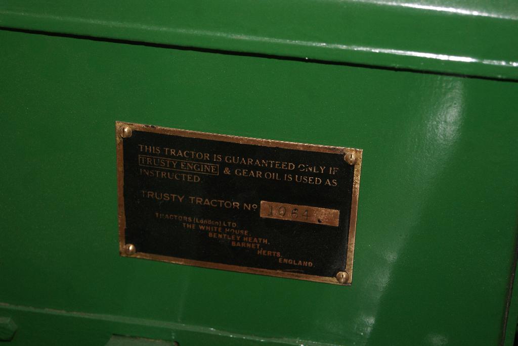
Once together and bolted up tight it was a breeze to paint it all and it really does make a difference to the overall look of the tractor. As I said in my last piece, it makes a big difference to use the correct old type bolts and screws and so I finished up today by securing the clutch cover with six 1/4″ Whitworth dome head screws that I ordered specially, then the toolbox front cover with two 2BA dome head screws and finally the serial number plate with four 5BA brass screws. Not much more to do now apart from touch up a few bolt heads with a paintbrush and do the artwork for the special transfer to go each side of the toolbox.
Attachments:
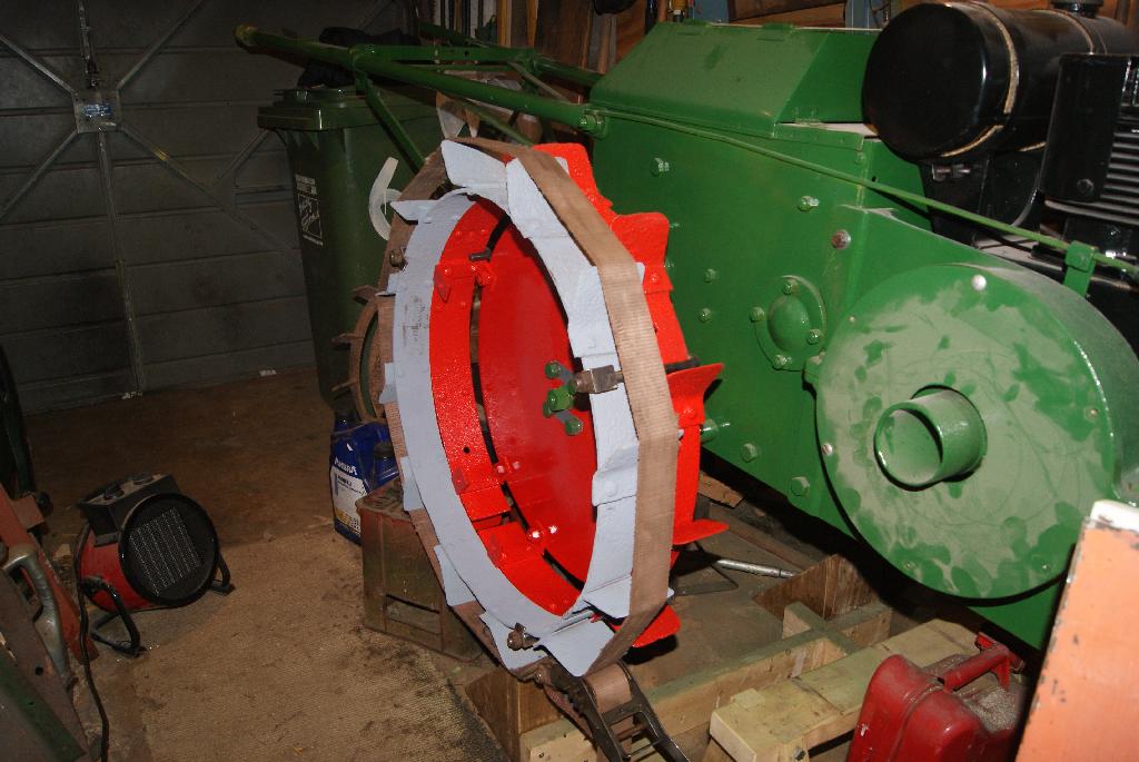
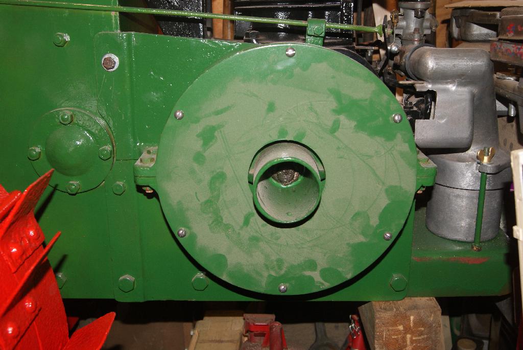
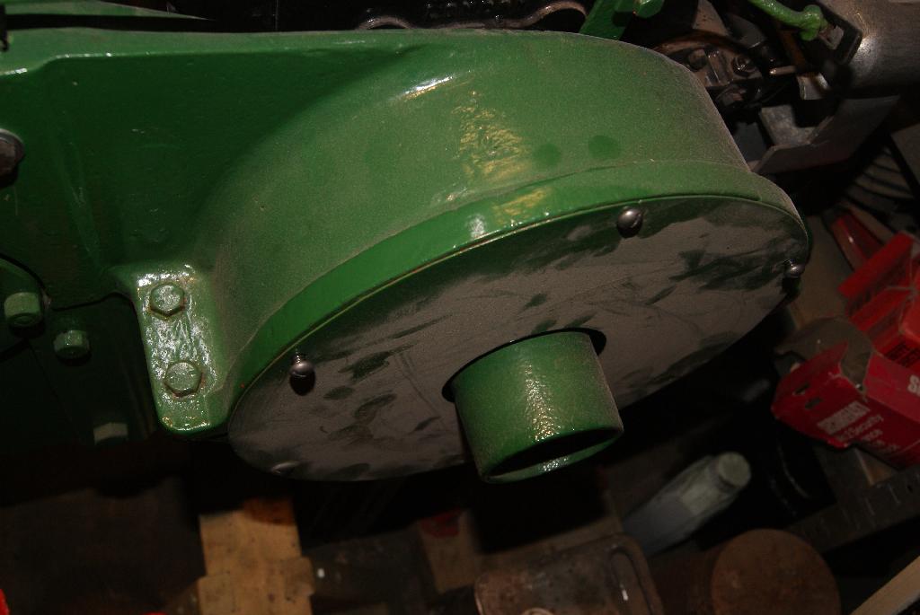
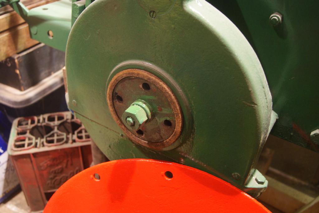
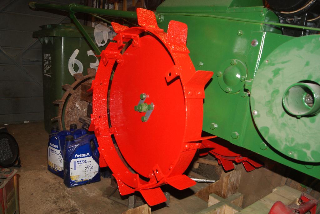
December 4, 2020 at 1:37 pm #36078trusty220KeymasterBoth sides are now dry so I decided to go all out today to try to get the most of the wheel done. Before fitting the disc I made sure that the felt seal was in place- I borrowed this off a couple of spare reduction gears that I have on the shelf, so imagine my surprise when I took the cast iron spacer off the outside and found a genuine Trusty Dust Cover protecting the felt seal. I took the other one apart and found another dust cover ( no surprise there, but you never know!). These are the only two covers that I have ever come across in all the years that I have been rebuilding Trusty’s, so I was chuffed to find them. I’ll clean them up and think of some way to display them otherwise they won’t be seen again for a long time if I use them on a tractor.
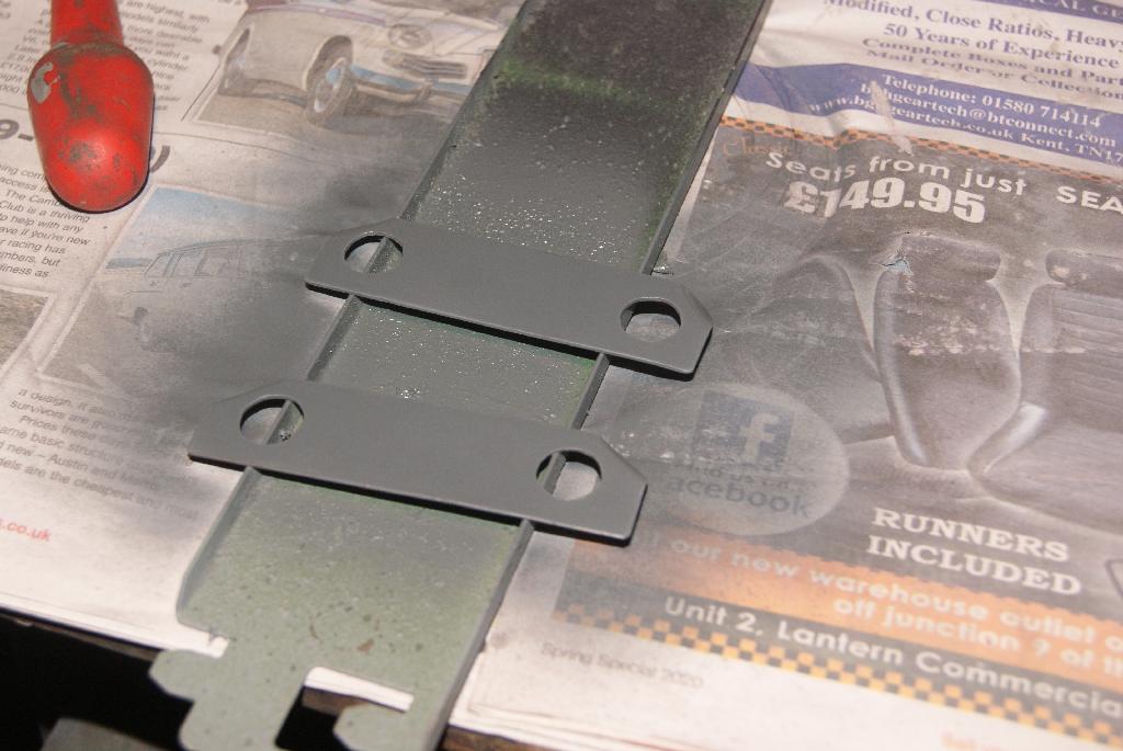
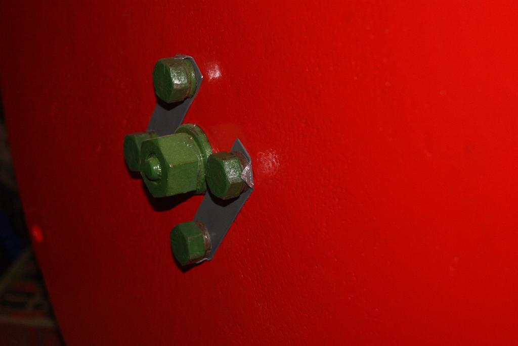
I mounted the disc on the tractor with two bolts and tightened them home. I then made up another two locking tabs, painted them and then used them to bolt the disc to the tractor permanently with four bolts that I had cleaned up and painted.
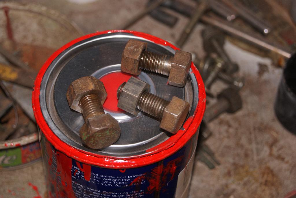
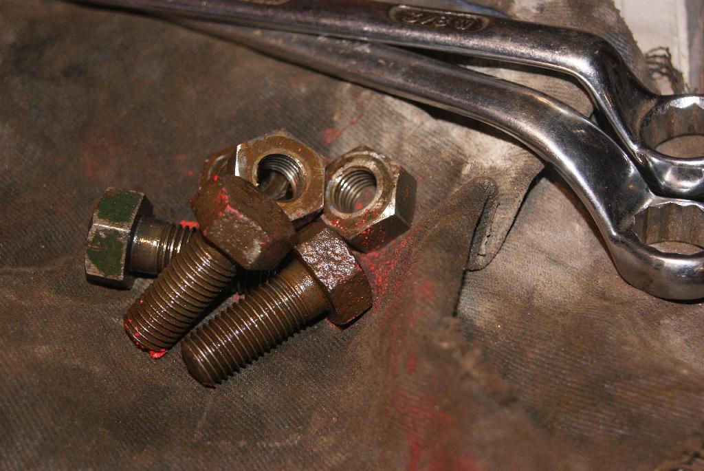
When rebuilding a machine like this I always try to save the old bolts to use again because they look different to anything new. For a start new bolts normally have a relief on both sides of the hexagon head whereas the old, original bolts have a thicker head and only have a relief on the outside. I think the idea was that the flush face that goes against the metalwork will have more contact area and therefore more friction; it will also “bite” into the metal to prevent it loosening in service. You can always tell when somebody has used the original bolts and I have managed to accumulate quite a few spares over the years from tractors that were beyond saving and reduced to spares. As for stainless metric bolts- don’t get me started!
You will see from the photo’s that I take quite a bit of time over cleaning old bolts up for re-use and it pays dividends with the finished product. These bolts in the photo’s I used to bolt the first row of strakes to the wheel disc.
Cup of tea time, methinks!
Attachments:
December 2, 2020 at 2:21 pm #36055trusty220KeymasterI’ve been working non-stop in the garage these last two days and don’t seem to have achieved very much. That’s the way it goes sometimes and the smallest fiddly jobs take up a lot of time if you want to get them right.
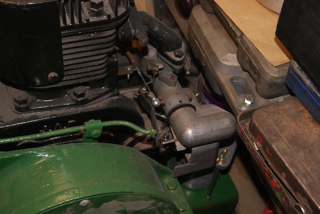
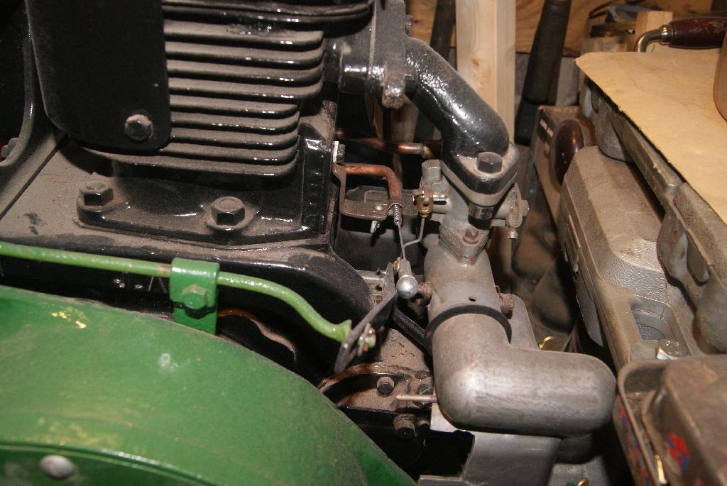
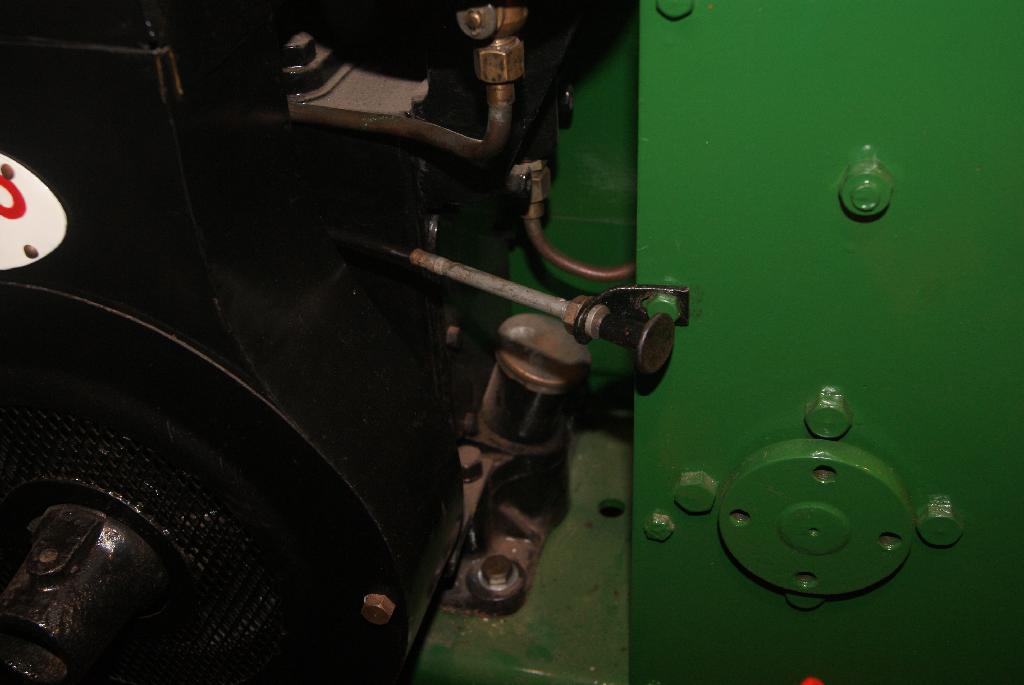
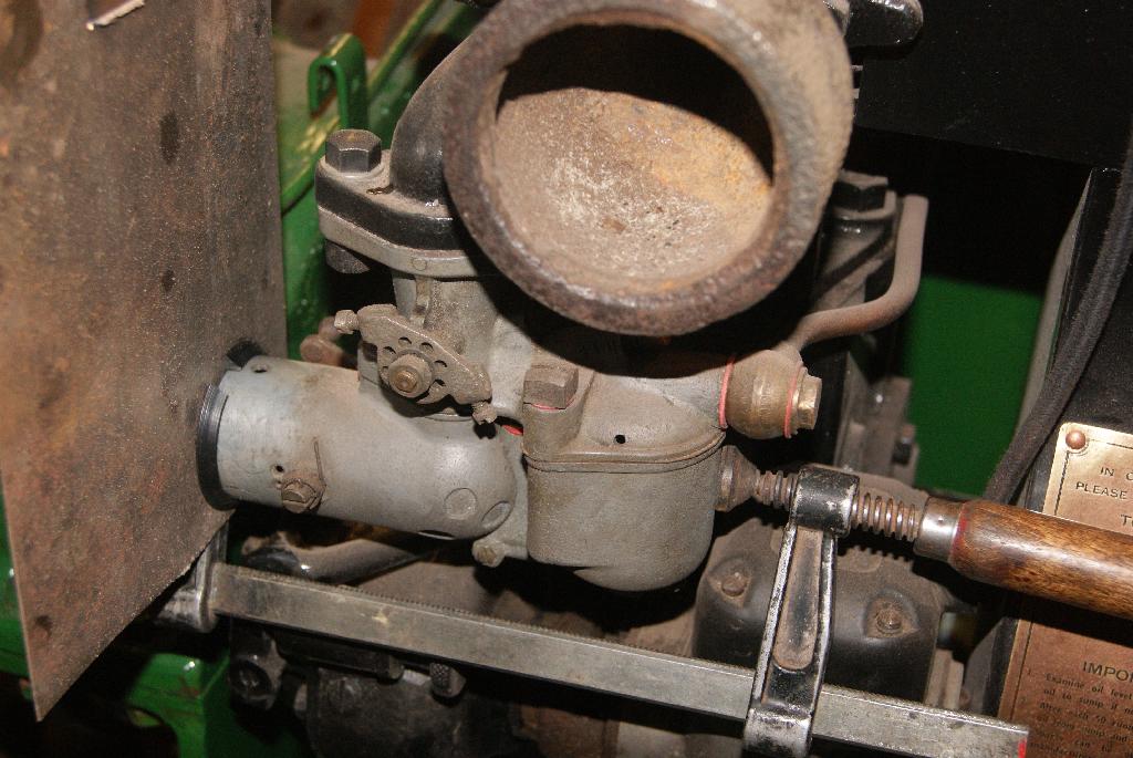
The first thing you’ll notice from the pictures is that I’ve turned the tractor around again to finish the work on the right hand side. I took the time to take some photo’s of the choke linkage from the other side, the side I couldn’t get to when I was working on it. You can see how tight the gaps are and why it had to be just right otherwise the whole lot would end up sticking with the throttle open.
The throttle rod and linkage are now bolted up, clutch housing bolted down and the right hand wheel removed so that I can play around with the correct wheel.
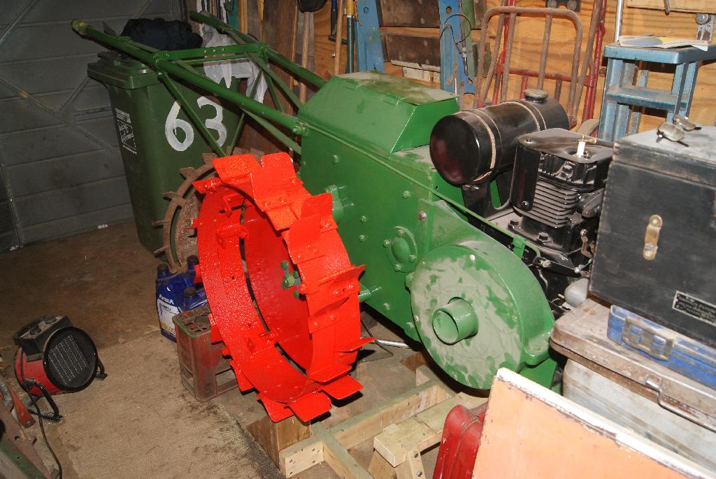
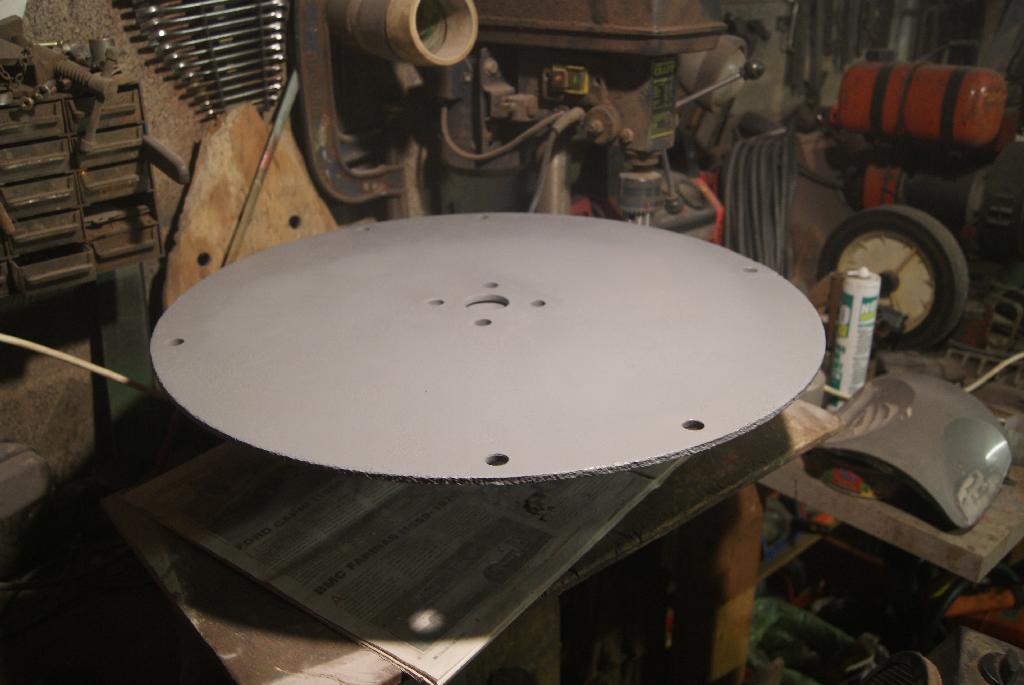
The next pictures are of the wheel disc that has been shot blasted, primed with red oxide then filled with P38 filler to achieve a smooth surface. I’ve just painted it with grey primer in the photo’s so you won’t see the first few stages, but I was going so well I didn’t want to stop!
Hopefully I’ll get the red enamel on tonight so that it can dry off overnight, then I can turn it over and do the same with the front side.
Attachments:
December 2, 2020 at 11:22 am #36043trusty220KeymasterThe magneto type should be A955BZ if anyone has a service sheet for this model- unfortunately I’ve got everything but that one!
November 30, 2020 at 9:15 am #36034trusty220KeymasterI am determined to complete this rebuild without using any specialist tools so that newcomers to this hobby can see what is achievable with only the most basic toolkit. Besides, I still can’t access my machine tools because they’re still in store ready for the house move when it happens.
Thanks for your kind words, Charlie. Problem solving is keeping my mind active during these Covid-19 blighted days. I hope the rest of the club members are coping with it in a similar fashion and let’s all hope we return to normality in the near future.
November 29, 2020 at 5:10 pm #36026trusty220KeymasterTime to finish the cable control today. Unfortunately I don’t think it was my day today as I had just finished the bracket and was screwing it onto the engine to check clearances for the last time and- something was wrong! Upon closer inspection it appeared that the cable outer was not securely fastened into the aluminium tube which housed the knob and slide. I tried to re-crimp it but the aluminium just cracked so I put it all down and had a cup of tea.
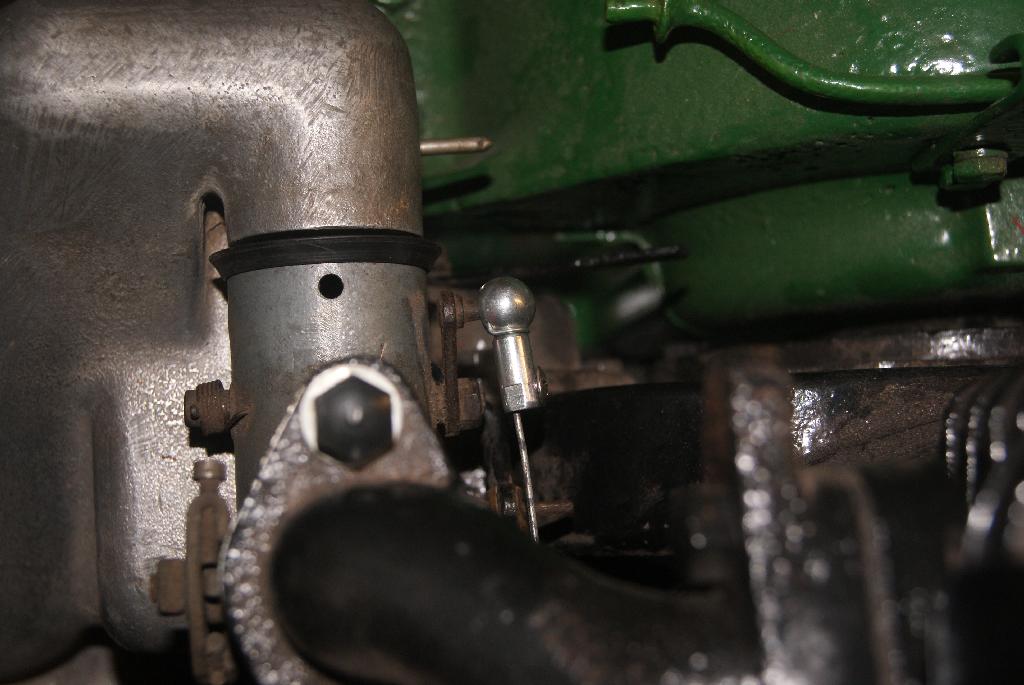
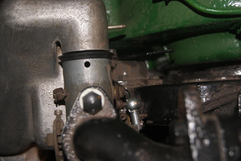
Looking in the spares box I managed to find another cable which would do the job, but it was slightly bigger in diameter and so would not pass through the copper tube like the old one did. Carefully I peeled off the outer plastic covering and that was enough to make it fit (just!). The only trouble was it would not go around the sharp bend, so the next thing to do was to ease the bend slightly and cut off half of the copper tube to help it swell out around the corner. That did the trick!
After countless trial fits and adjustments I finally got the cable to sit exactly where I wanted it, so a quick drill and tap to put a thread and a grub screw into the ball joint and the whole lot is now bolted up tight and, even better, it works!
Now where did I put that Laphraoig??
Attachments:
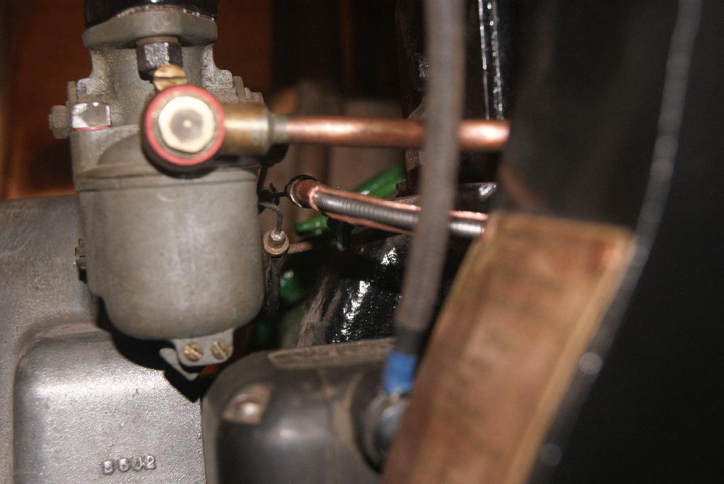
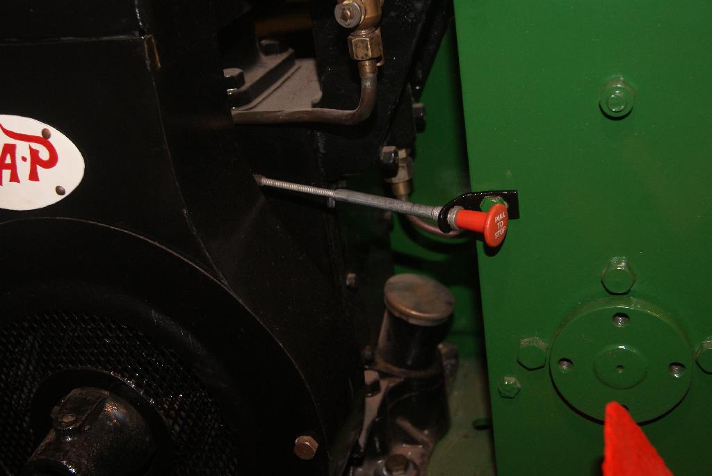
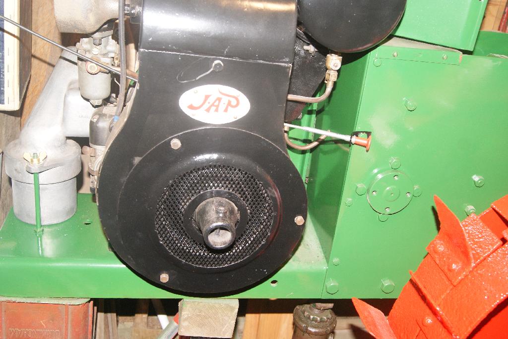
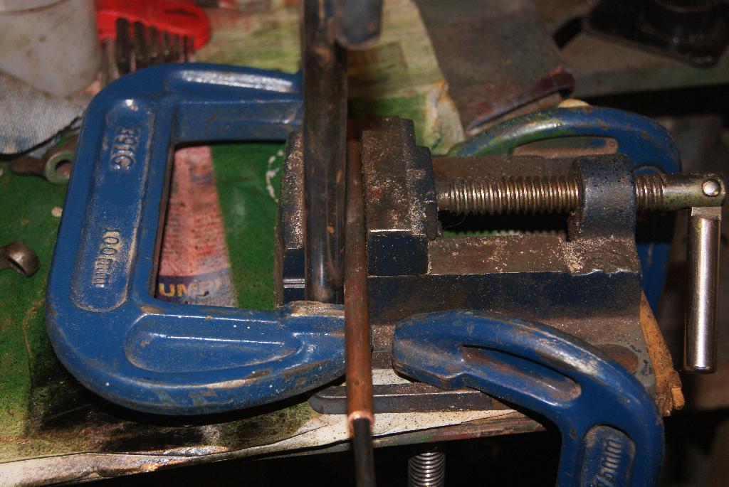
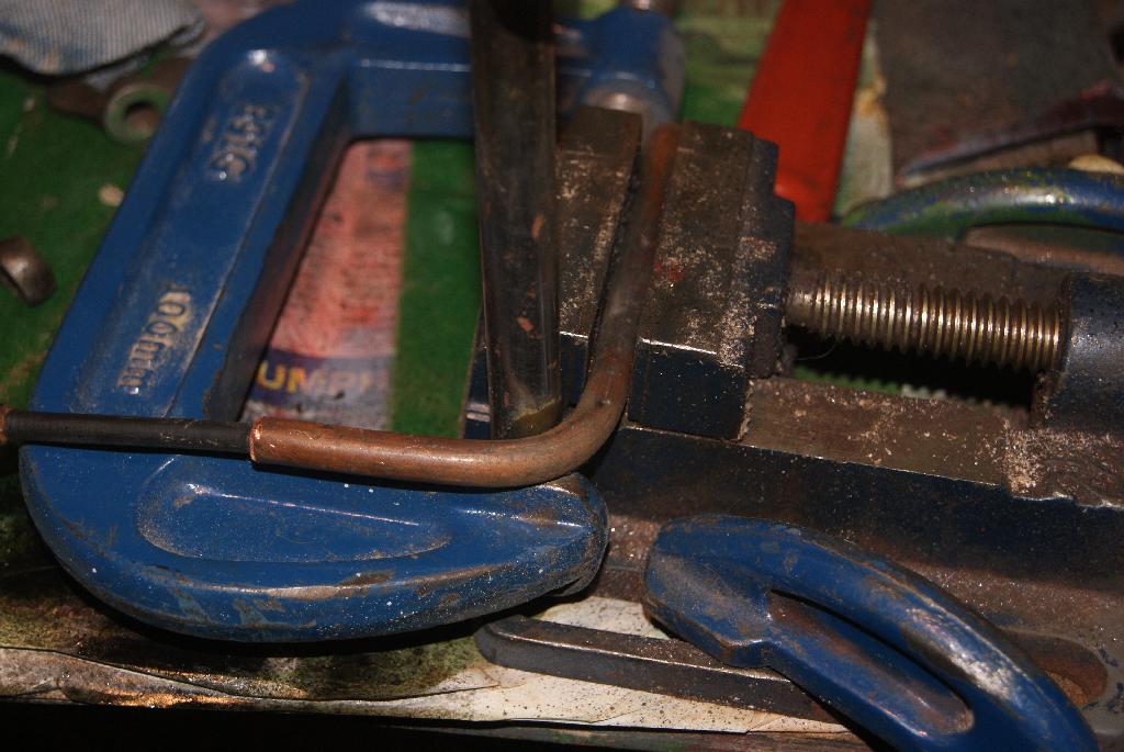
November 28, 2020 at 9:33 pm #36012trusty220KeymasterYou will see from the first picture that the choke cable was really only cobbled together by the previous owner and it passed around the outside of the cowling. The choke lever itself on the carburetter was fitted with a ball joint, half of which was missing and the cable was wrapped around the ball fitted to the bellcrank. It worked but didn’t look elegant at all and so I had to do something different.
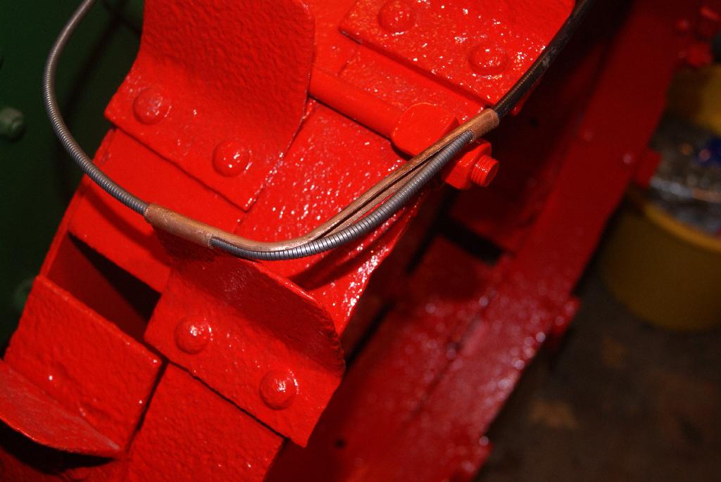
The cable needed to go behind the flywheel cowling, then turn sharp right in front of the valve chest, pass close to the governor linkage and connect with the ball on the choke bellcrank. The original bracket was cut down and relocated in a more sensible place, the cable could then pass behind the flywheel. Now, how to get it to turn sharp so that it misses the governor linkage; if left to find it’s own course it will rub on the linkage and jam the throttle.
I hit on the idea of running the cable through a 1/4″ copper gas pipe, bent through 90 degrees and secured to the valve chest with another bracket. The pipe was cut to length, annealed by heating with a blowtorch and then bent through the required angle using the jig in the picture. So that the pipe did not collapse I put an old cable through it before I started to bend it, then pulled it out and tried a dry fitting to test the clearances.
Attachments:
November 28, 2020 at 9:17 pm #36008trusty220KeymasterTime to take the clamps off today and everything was as I predicted. The rubber grommet had stayed put and actually looked quite professional, so back together everything went and the whole assembly tightened down with the new brass wingnuts. It all looks the part, so I’m happy with that stage and will move on to sorting out the choke cable.
Attachments:
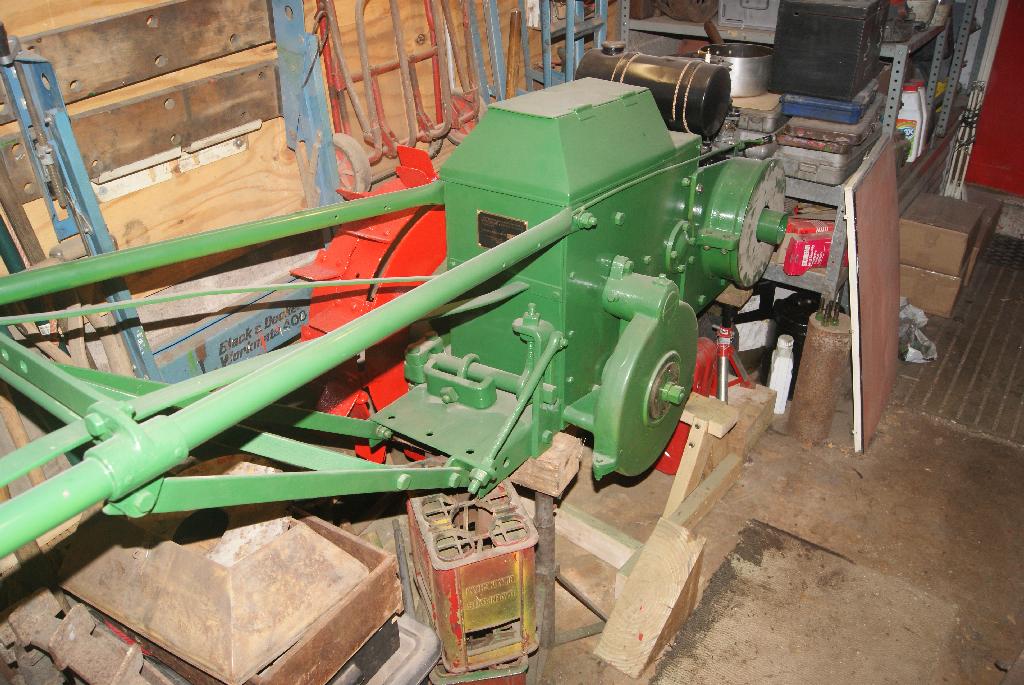
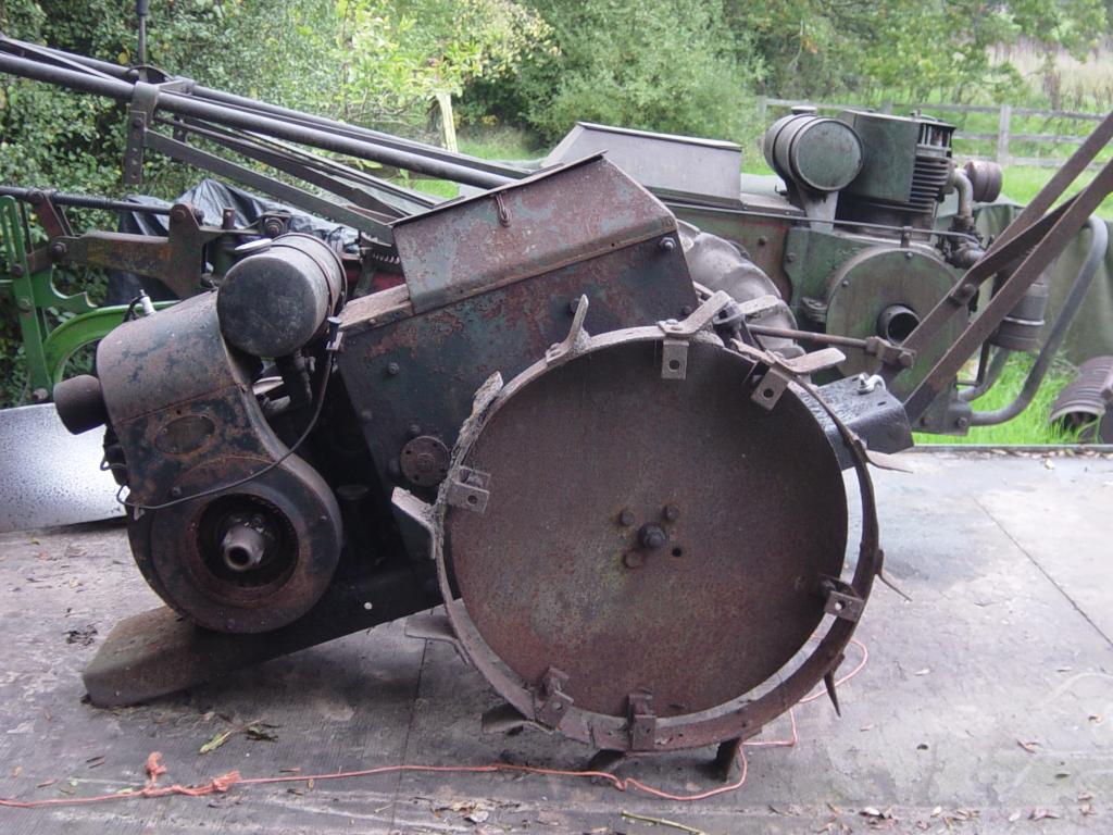
November 24, 2020 at 2:33 pm #35978trusty220KeymasterThe trailer is now finished and back out of the barn, the two Internationals are now in the barn out of the weather for the winter and the fields are too wet to do anything on, so it’s back to the Trusty.
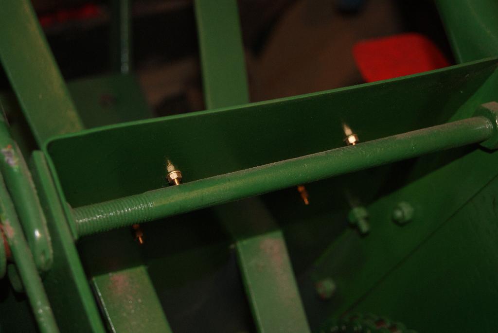
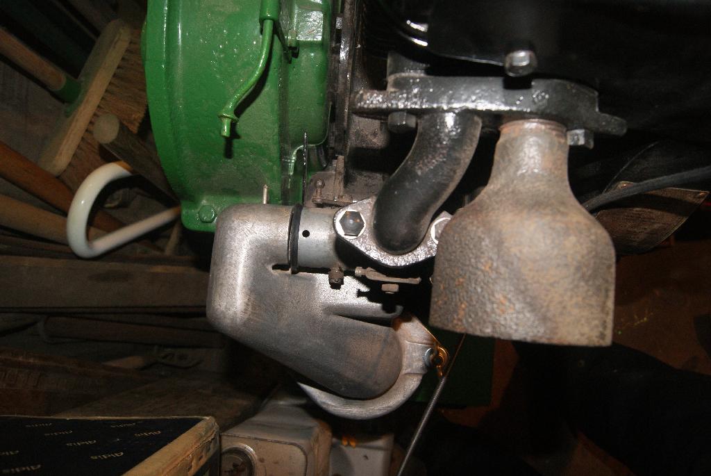
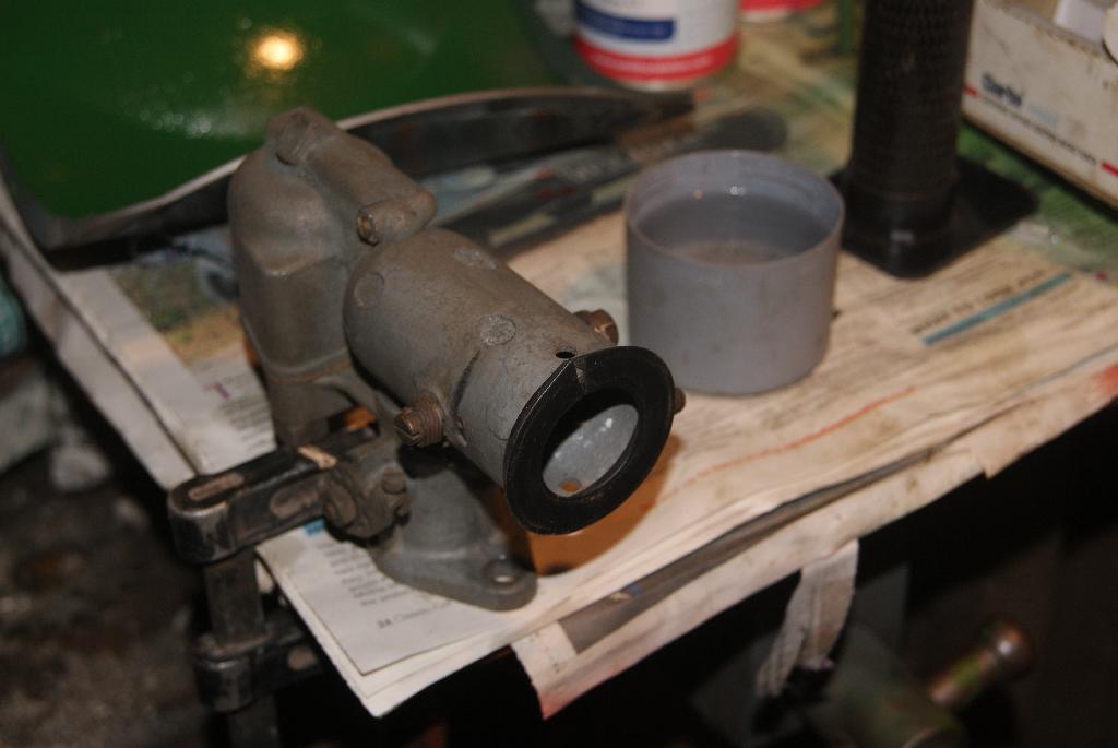
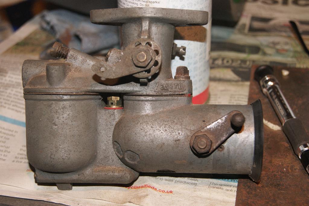
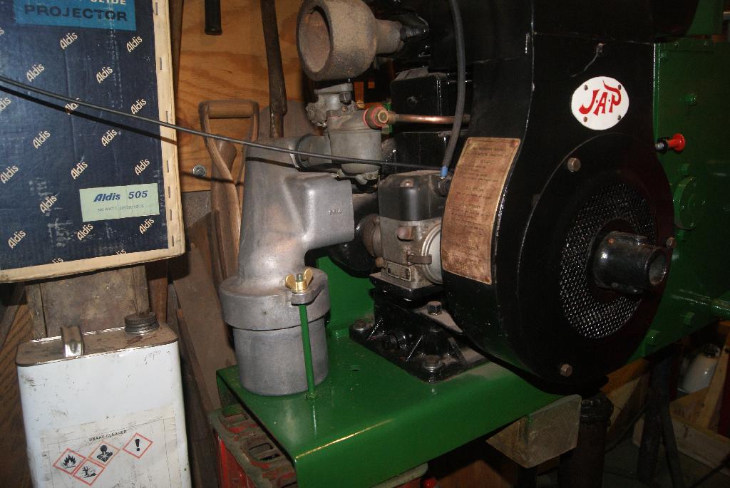
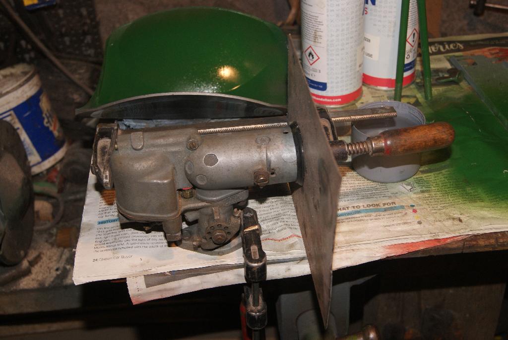
With the first wheel finished and painted it was time to sort out the front end before I lower it down and turn it around so that I can work on the second wheel. The air filter is a distinctive feature of this early model and it simply has to be right; what I can’t work out is how the top of the filter is supposed to connect with the carburetter. The lower part is easy enough to work out and all I needed to do was to make up some rods that screwed through the chassis. The top of these go through hooks on the top of the filter housing and hold the top housing down to the base. I’ve ordered up some wing nuts to complete the job, so they should look the part once they arrive.
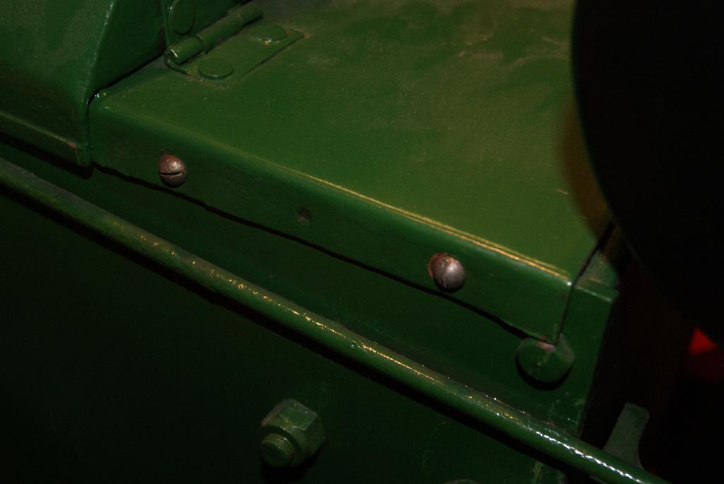
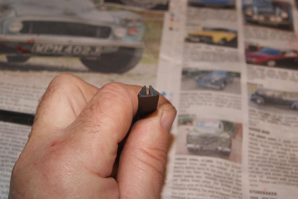
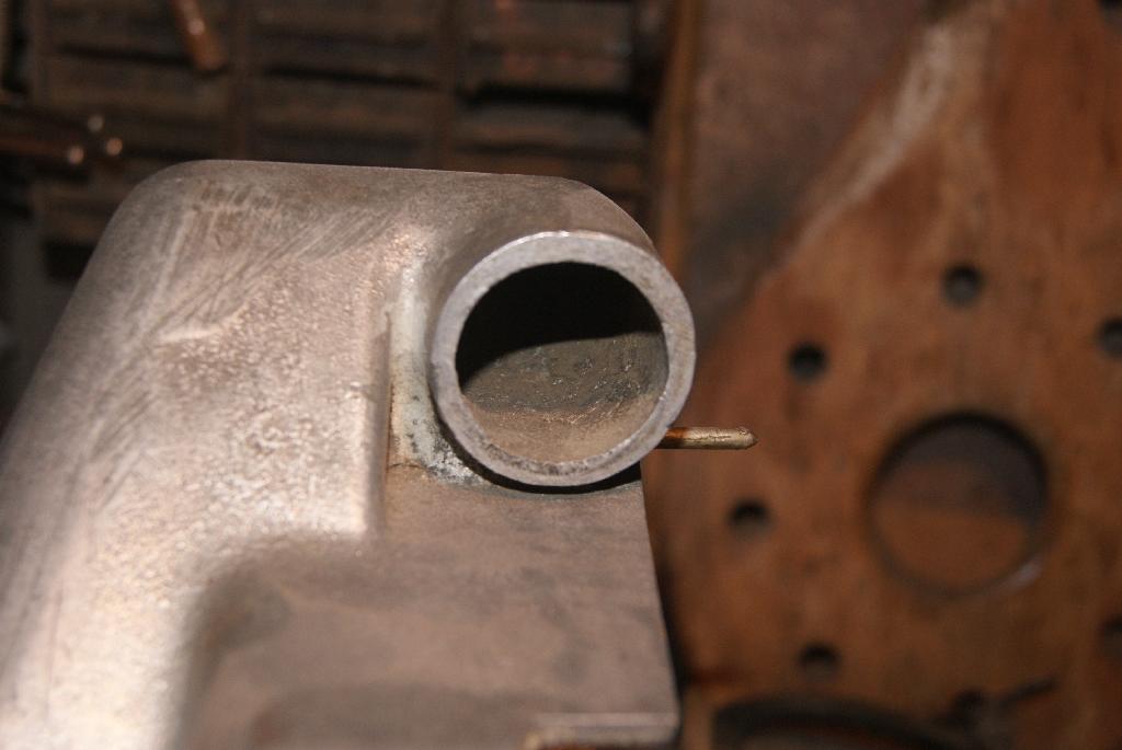
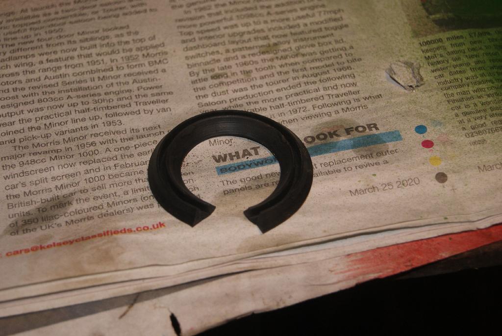
At the top of the housing there is a cast tube which is exactly the same diameter as the inlet of the carb. Unfortunately there is not enough gap at the bottom of the tube to bridge the space with a piece of radiator hose but at the back of the housing there is a small post with a hole at the end; I’m guessing that it was far a spring to hold the housing against the carburetter, so I decided to use some rubber that I have for holding the overriders to the bumper on the GT6. It’s flat one side with a groove in the other (see picture) and would look just right if I could get it to go round the small tube.
The secret to getting it workable is to get it hot, so into boiling water it went and then quickly pressed into position to cool. That sounds easy but took quite a few attempts before an acceptable result was achieved, then I found I’d cut it too short! Never mind, it was an experiment to see if I could get it to retain it’s shape, so I made another one a little longer and trimmed it to fit at the end. Clamping a steel plate over it, I heated up the carburetter body and the steel plate then left it to cool and it worked! I’ve now taken it all apart and put expanding glue inside, then clamped it all up again.
Cup of tea time, methinks!
Attachments:
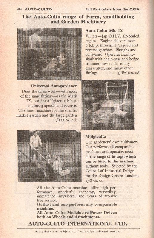
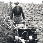
November 23, 2020 at 12:05 pm #35972trusty220KeymasterHere is the relevant page from the CLA Price Guide from 1963. The Midgiculto looks like it may have a Villiers engine on it, but the picture is so small that it won’t expand enough to see any detail.
Attachments:
November 23, 2020 at 11:35 am #35971trusty220KeymasterThe hydrostat looks like an Eaton one similar to the one used on the Jacobsen Tri-King.
November 20, 2020 at 5:31 pm #35939trusty220KeymasterNow then, a subject dear to my heart is this aviation thingy.
The answer to No.3 is Brompton in Yorkshire where George Cayley conducted his experiments with flying objects. His coachman is said to have resigned after being forced to fly one of Cayley’s gliders!
No.4 is Scarborough, also in Yorkshire.
Can I answer all of the questions with “Yorkshire!”??
…and I still think the Pope came from Sheffield!November 20, 2020 at 5:23 pm #35937trusty220KeymasterYou’re wrong, Alan. I have it on good authority that the Pope came from Sheffield.
Am I right?
November 18, 2020 at 10:45 am #35862trusty220KeymasterD’Oh! I blame either Muppetry or Laphraoig! I’ve just noticed my typo so please accept my apologies, Mr. Wallingfield.
What I meant to put was 5th September, 1959 but I think my brain got a bit confused with all these numbers. I think it must be my age!
Live long and prosper, Andrew!
November 17, 2020 at 9:02 am #35848trusty220KeymasterSome people use a differential expansion method to break the rust seal- once it’s all cherry red pour cold water on the outside but stand well back because it spits steam everywhere. I tend to build up a big fire in an oil drum over at the farm, put the item in it to heat up thoroughly for 30 minutes then take it out quickly and immerse it in the stream. The different expansion and contraction between the two items tends to break the rust up. It hasn’t failed me yet!
-
AuthorPosts