Home › Forums › The Main Forum Area › Projects › Early Trusty Rebuild
- This topic has 101 replies, 14 voices, and was last updated 4 years, 2 months ago by
 trusty220.
-
AuthorPosts
-
November 28, 2020 at 9:17 pm #36008
 trusty220Keymaster
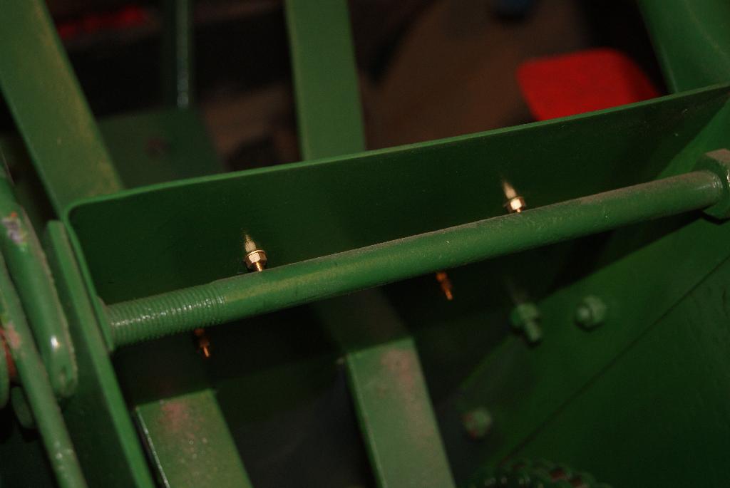
Time to take the clamps off today and everything was as I predicted. The rubber grommet had stayed put and actually looked quite professional, so back together everything went and the whole assembly tightened down with the new brass wingnuts. It all looks the part, so I’m happy with that stage and will move on to sorting out the choke cable.
Attachments:
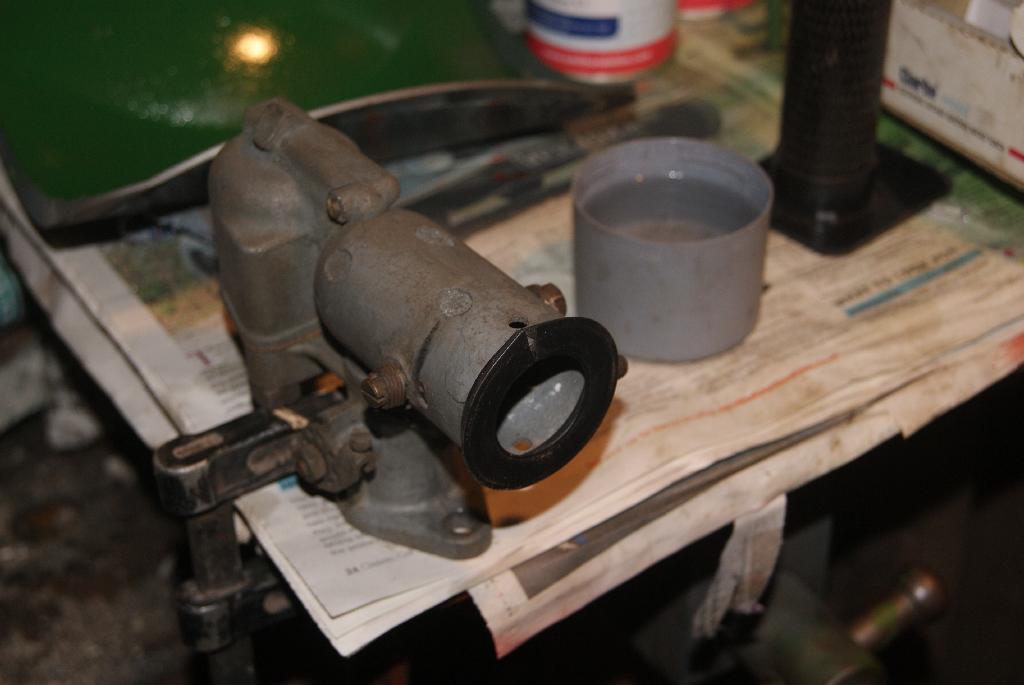
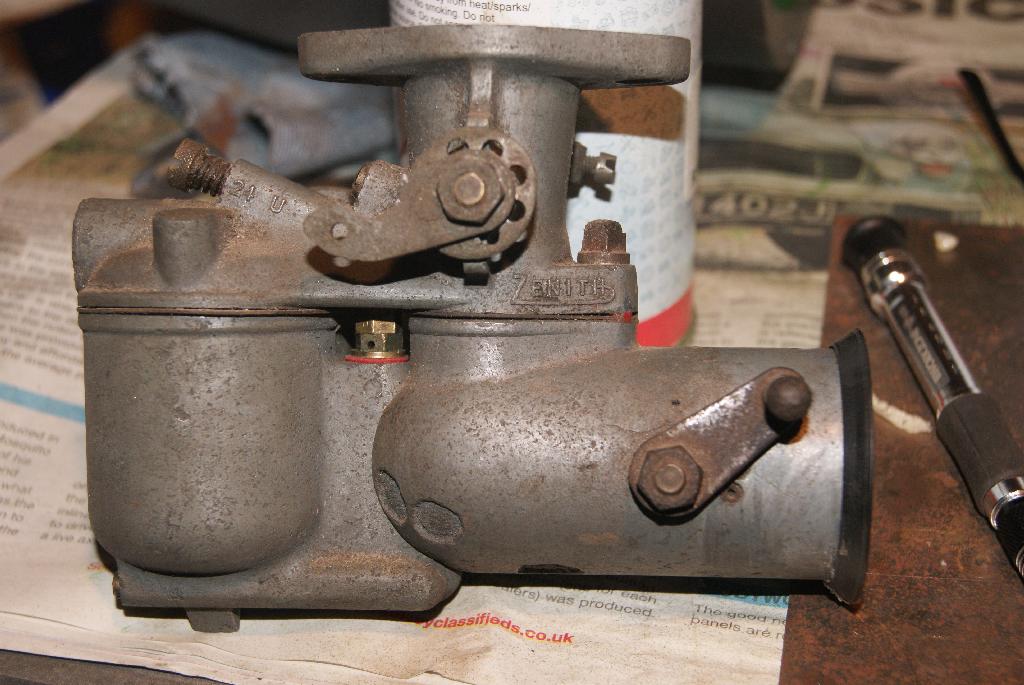
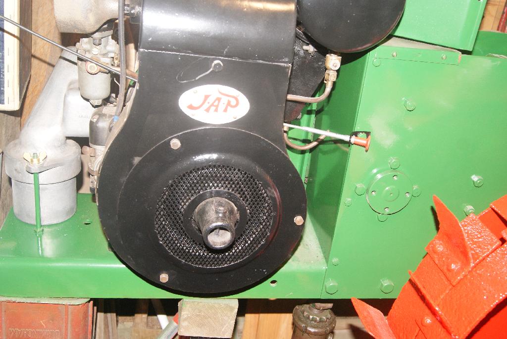
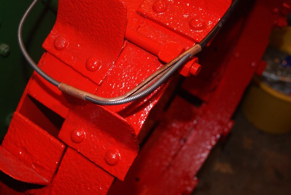
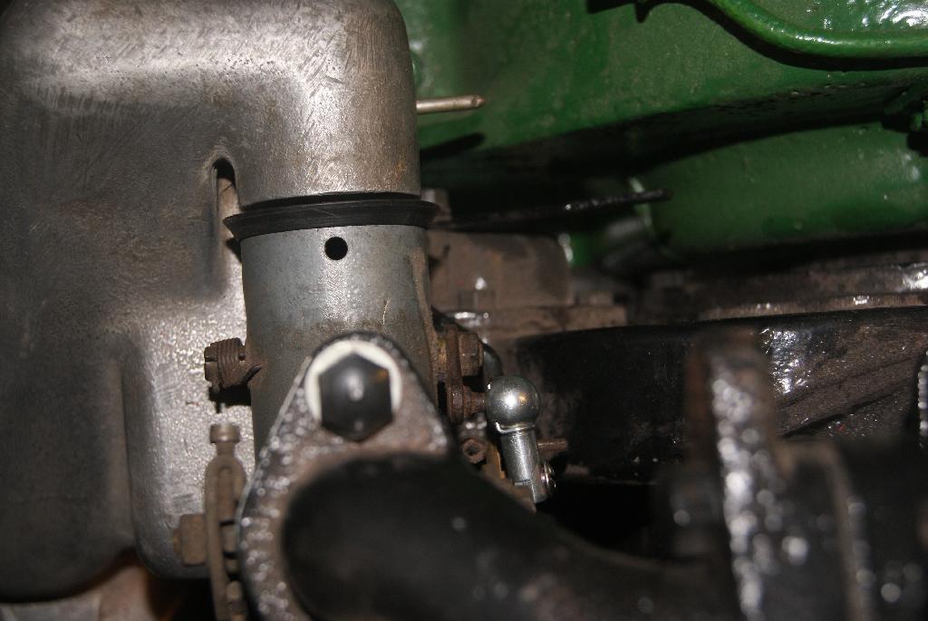
November 28, 2020 at 9:33 pm #36012trusty220KeymasterYou will see from the first picture that the choke cable was really only cobbled together by the previous owner and it passed around the outside of the cowling. The choke lever itself on the carburetter was fitted with a ball joint, half of which was missing and the cable was wrapped around the ball fitted to the bellcrank. It worked but didn’t look elegant at all and so I had to do something different.
The cable needed to go behind the flywheel cowling, then turn sharp right in front of the valve chest, pass close to the governor linkage and connect with the ball on the choke bellcrank. The original bracket was cut down and relocated in a more sensible place, the cable could then pass behind the flywheel. Now, how to get it to turn sharp so that it misses the governor linkage; if left to find it’s own course it will rub on the linkage and jam the throttle.
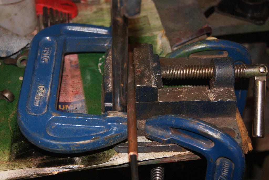
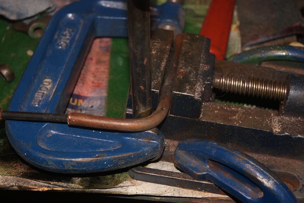
I hit on the idea of running the cable through a 1/4″ copper gas pipe, bent through 90 degrees and secured to the valve chest with another bracket. The pipe was cut to length, annealed by heating with a blowtorch and then bent through the required angle using the jig in the picture. So that the pipe did not collapse I put an old cable through it before I started to bend it, then pulled it out and tried a dry fitting to test the clearances.
Attachments:
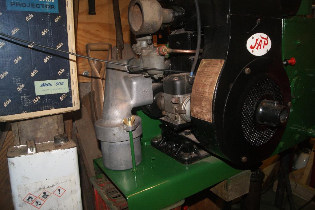
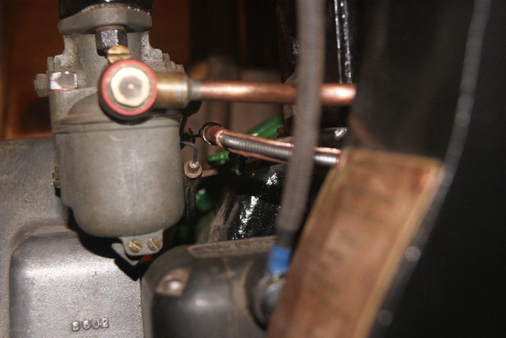
November 29, 2020 at 5:10 pm #36026trusty220KeymasterTime to finish the cable control today. Unfortunately I don’t think it was my day today as I had just finished the bracket and was screwing it onto the engine to check clearances for the last time and- something was wrong! Upon closer inspection it appeared that the cable outer was not securely fastened into the aluminium tube which housed the knob and slide. I tried to re-crimp it but the aluminium just cracked so I put it all down and had a cup of tea.
Looking in the spares box I managed to find another cable which would do the job, but it was slightly bigger in diameter and so would not pass through the copper tube like the old one did. Carefully I peeled off the outer plastic covering and that was enough to make it fit (just!). The only trouble was it would not go around the sharp bend, so the next thing to do was to ease the bend slightly and cut off half of the copper tube to help it swell out around the corner. That did the trick!
After countless trial fits and adjustments I finally got the cable to sit exactly where I wanted it, so a quick drill and tap to put a thread and a grub screw into the ball joint and the whole lot is now bolted up tight and, even better, it works!
Now where did I put that Laphraoig??
Attachments:
November 30, 2020 at 8:03 am #36033 charlieKeymaster
Another good example of how our hobby involves all sorts of skills and thinking around problems.
November 30, 2020 at 9:15 am #36034trusty220KeymasterI am determined to complete this rebuild without using any specialist tools so that newcomers to this hobby can see what is achievable with only the most basic toolkit. Besides, I still can’t access my machine tools because they’re still in store ready for the house move when it happens.
Thanks for your kind words, Charlie. Problem solving is keeping my mind active during these Covid-19 blighted days. I hope the rest of the club members are coping with it in a similar fashion and let’s all hope we return to normality in the near future.
December 2, 2020 at 2:21 pm #36055trusty220KeymasterI’ve been working non-stop in the garage these last two days and don’t seem to have achieved very much. That’s the way it goes sometimes and the smallest fiddly jobs take up a lot of time if you want to get them right.
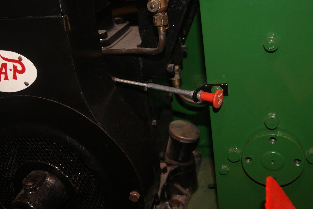
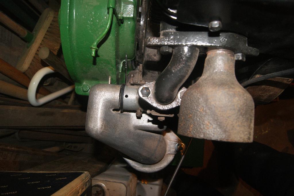
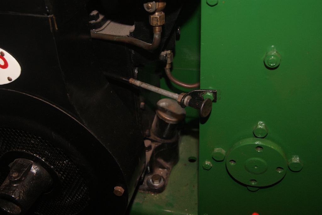
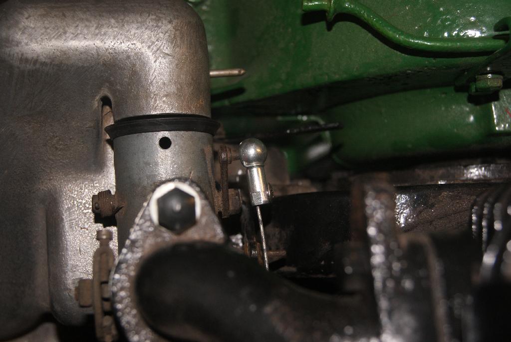
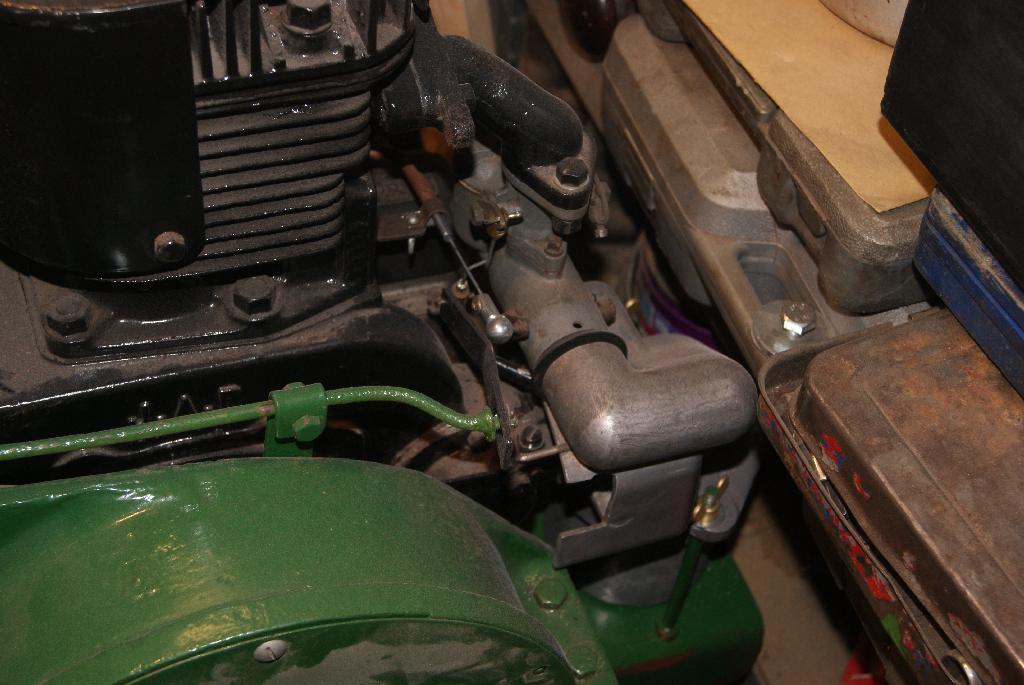
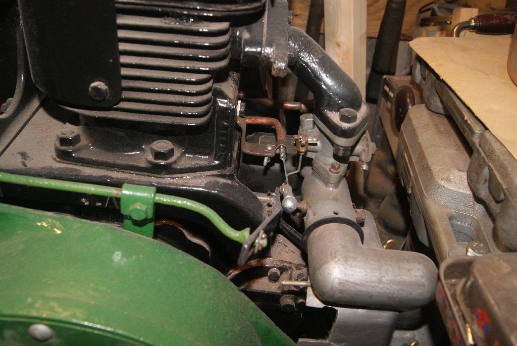
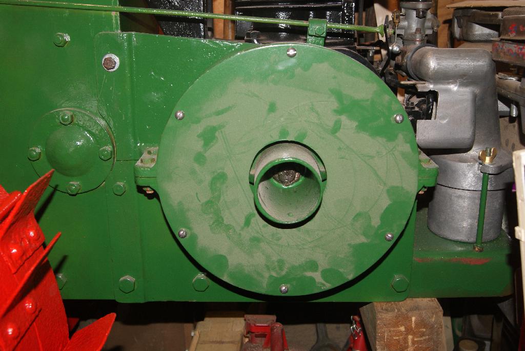
The first thing you’ll notice from the pictures is that I’ve turned the tractor around again to finish the work on the right hand side. I took the time to take some photo’s of the choke linkage from the other side, the side I couldn’t get to when I was working on it. You can see how tight the gaps are and why it had to be just right otherwise the whole lot would end up sticking with the throttle open.
The throttle rod and linkage are now bolted up, clutch housing bolted down and the right hand wheel removed so that I can play around with the correct wheel.
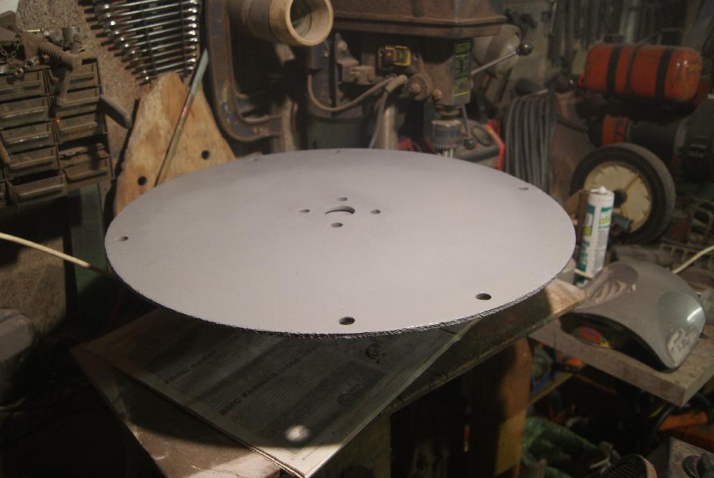
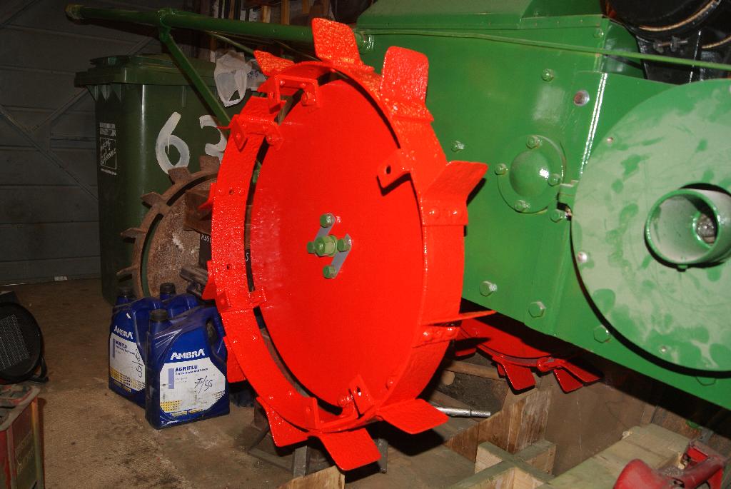
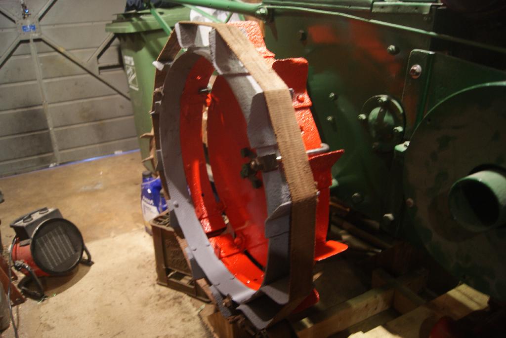
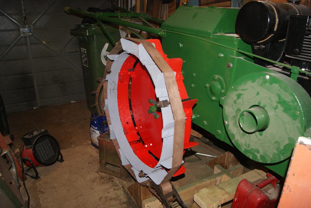
The next pictures are of the wheel disc that has been shot blasted, primed with red oxide then filled with P38 filler to achieve a smooth surface. I’ve just painted it with grey primer in the photo’s so you won’t see the first few stages, but I was going so well I didn’t want to stop!
Hopefully I’ll get the red enamel on tonight so that it can dry off overnight, then I can turn it over and do the same with the front side.
Attachments:
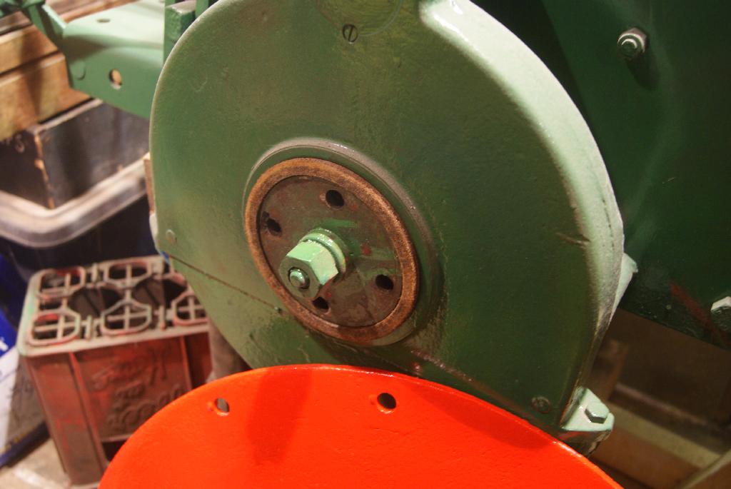
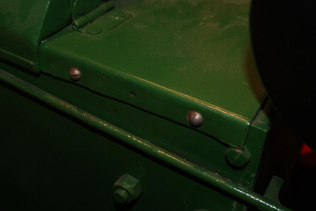
December 4, 2020 at 1:37 pm #36078trusty220KeymasterBoth sides are now dry so I decided to go all out today to try to get the most of the wheel done. Before fitting the disc I made sure that the felt seal was in place- I borrowed this off a couple of spare reduction gears that I have on the shelf, so imagine my surprise when I took the cast iron spacer off the outside and found a genuine Trusty Dust Cover protecting the felt seal. I took the other one apart and found another dust cover ( no surprise there, but you never know!). These are the only two covers that I have ever come across in all the years that I have been rebuilding Trusty’s, so I was chuffed to find them. I’ll clean them up and think of some way to display them otherwise they won’t be seen again for a long time if I use them on a tractor.
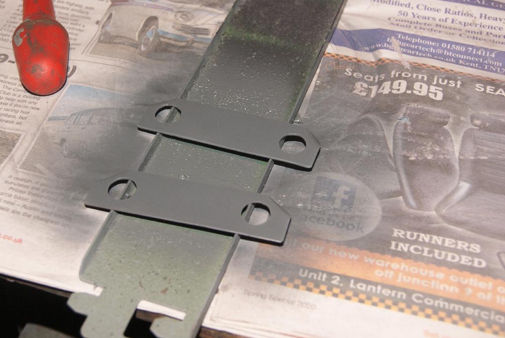
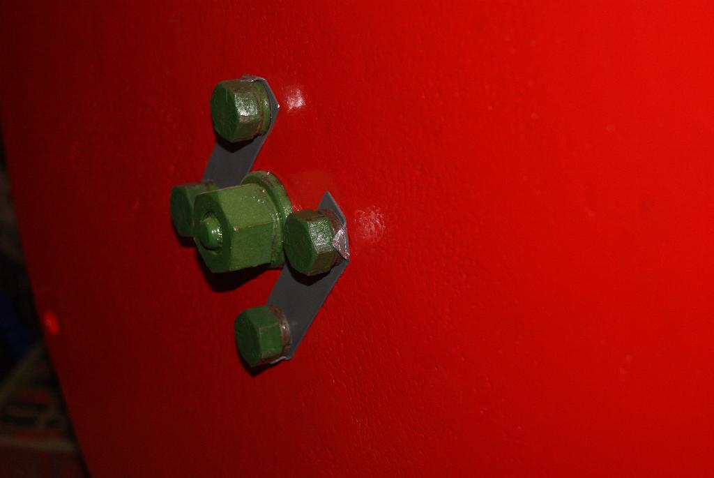
I mounted the disc on the tractor with two bolts and tightened them home. I then made up another two locking tabs, painted them and then used them to bolt the disc to the tractor permanently with four bolts that I had cleaned up and painted.
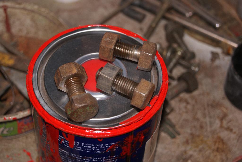
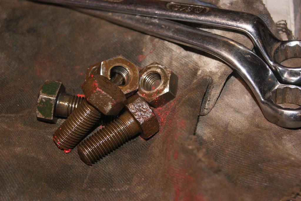
When rebuilding a machine like this I always try to save the old bolts to use again because they look different to anything new. For a start new bolts normally have a relief on both sides of the hexagon head whereas the old, original bolts have a thicker head and only have a relief on the outside. I think the idea was that the flush face that goes against the metalwork will have more contact area and therefore more friction; it will also “bite” into the metal to prevent it loosening in service. You can always tell when somebody has used the original bolts and I have managed to accumulate quite a few spares over the years from tractors that were beyond saving and reduced to spares. As for stainless metric bolts- don’t get me started!
You will see from the photo’s that I take quite a bit of time over cleaning old bolts up for re-use and it pays dividends with the finished product. These bolts in the photo’s I used to bolt the first row of strakes to the wheel disc.
Cup of tea time, methinks!
Attachments:
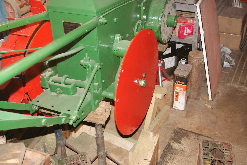
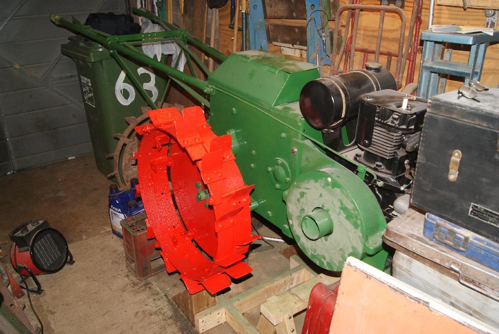
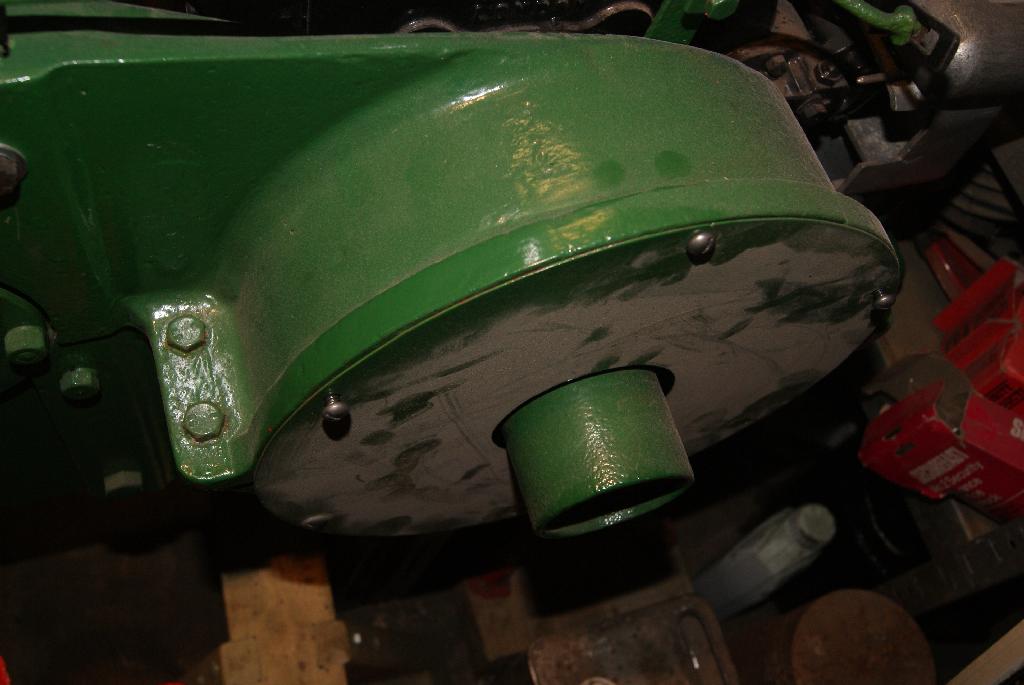
December 5, 2020 at 4:52 pm #36105trusty220KeymasterOh dear, I’d forgotten the lessons I learnt when putting on the outer ring of the first wheel. The best advice I could give is to let someone else do it! Not having anyone else to give it to, I settled on trying to find the best match for the gaps/strakes. After half an hour of swearing I gave up and just put a clamp on the outer ring in the point furthest away from the join- if you remember, the ring is circular (sort of) but the ends are not welded together, they just float freely.
So, clamp on the middle point opposite where the join is, then feed one half of the ring onto the first row, settling it down with a rubber mallet (it hurts your fingers less), clamping it down every foot with a hook bolt and levering/swearing/hammering it until you get to the free end. I then put a ratchet strap around the outside of the strakes to pull it into some form of a circle and repeated the process. I can see why they didn’t keep this design of wheel for very long!
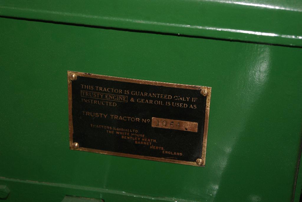
Once together and bolted up tight it was a breeze to paint it all and it really does make a difference to the overall look of the tractor. As I said in my last piece, it makes a big difference to use the correct old type bolts and screws and so I finished up today by securing the clutch cover with six 1/4″ Whitworth dome head screws that I ordered specially, then the toolbox front cover with two 2BA dome head screws and finally the serial number plate with four 5BA brass screws. Not much more to do now apart from touch up a few bolt heads with a paintbrush and do the artwork for the special transfer to go each side of the toolbox.
Attachments:
December 13, 2020 at 4:57 pm #36161halfa
ParticipantLooking great ! Can’t wait to see her with some stickers.
December 14, 2020 at 9:24 am #36168trusty220KeymasterThe transfers are taking a little time. I’m halfway through the artwork but took time out to restore an old Terry’s Anglepoise lamp that I rescued from my parents’ house when we cleared it; that and trying to protect the chicken runs from Avian Flu it’s been a little hectic lately.
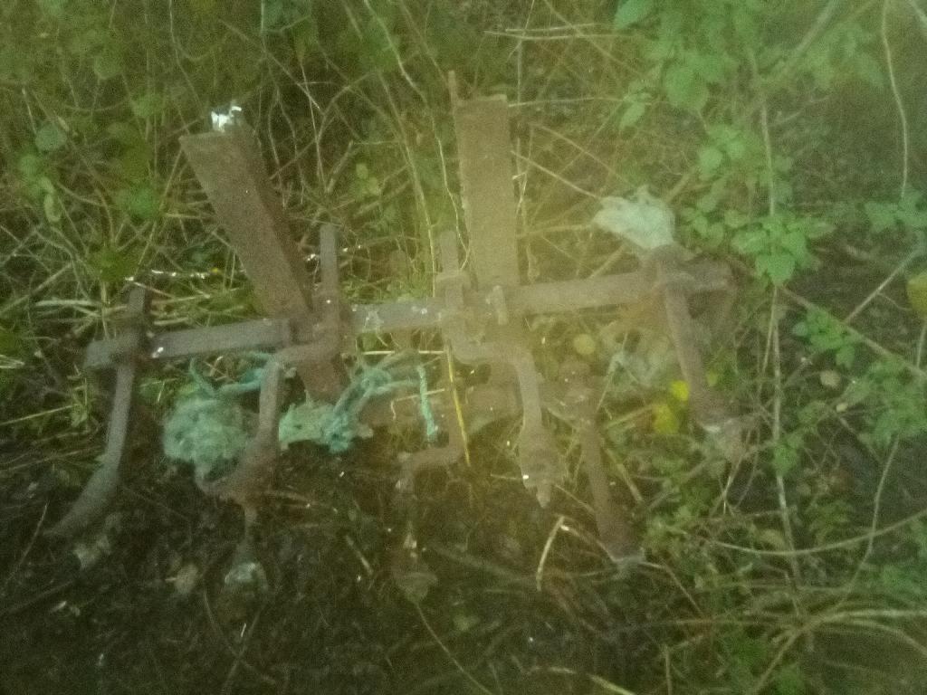
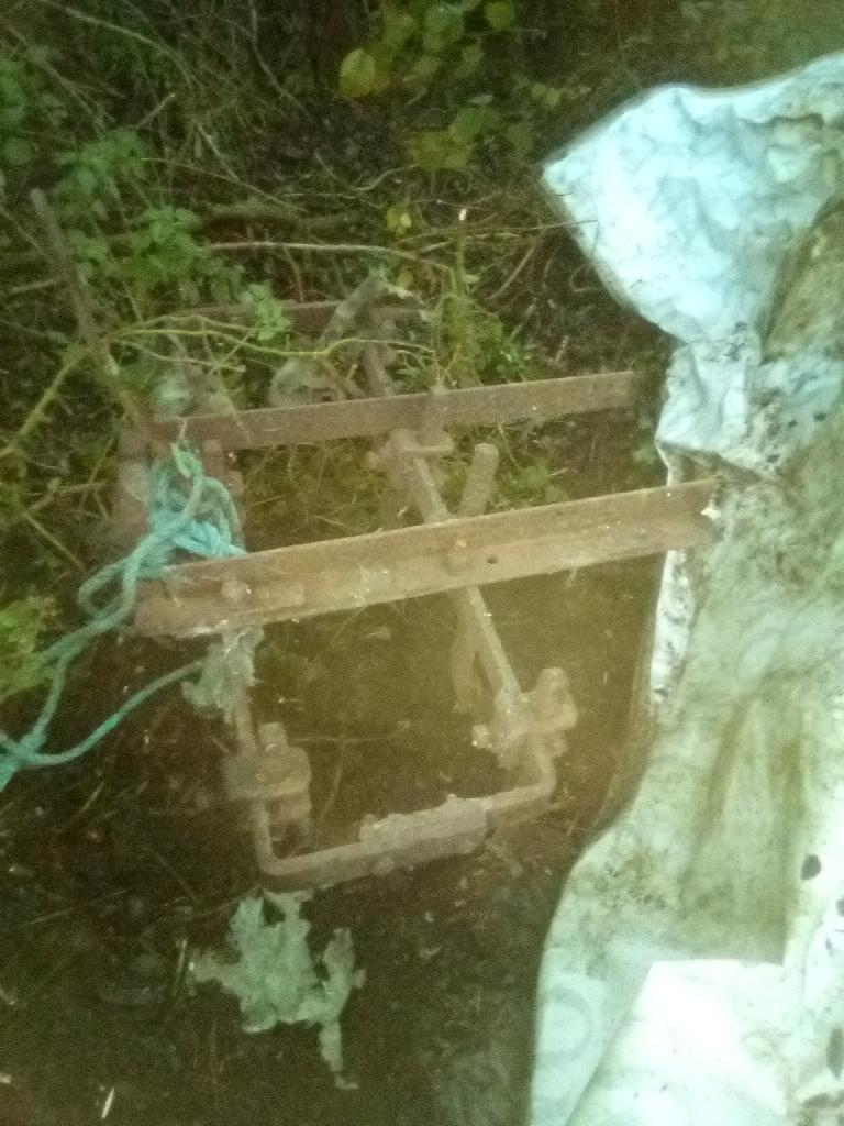
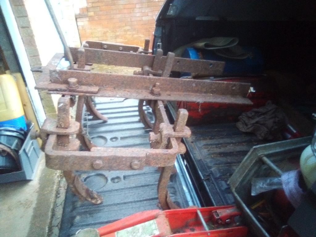
Hopefully I will be able to get down to finishing the artwork today and then we’ll see how good it is. Oh, and I almost forgot, I’ve been digging around at the farm in my “To Do” pile looking for a suitable attachment to go on the back to counterbalance the tractor. It’s no good restoring just the tractor if it’s just going to sit there with it’s nose on the ground. A plough came with this one (which has the special linkage on the front) but I’ve already got a restored plough of this sort on Trusty 220, so I managed to find a rigid tine cultivator that should look good on the back. At least it’s something different that you don’t see every day.
December 17, 2020 at 12:03 pm #36177trusty220KeymasterA couple of things for you to catch up on this time. Firstly, the transfers are taking a little longer than I anticipated because I keep learning new things with Photoshop which improve the appearance; I then throw away all that I’ve done up until then and start again! Frustrating, but rewarding learning a new skill. I’ve included a couple of pictures to show the original transfer on a tractor and my progress so far. The transfer may look a little rough but it will clean up with the later processes; my time is spent at present getting all of the letters in the right places and all the same widths.
The other time that I’ve spent (in the rain, funnily enough) is digging out the cultivator and dismantling it so that I can strip it of it’s rust and repair all of the messed-up threads in the tine clamps. Ideally they should all be of the same thread so that I only need one spanner to adjust. So far I have counted three different threads, and not all of them Imperial.
This may take a little longer than I thought.
Attachments:
December 17, 2020 at 3:13 pm #36184charlieKeymasterI can appreciate how long the transfers must be taking from the small amount of photo editing I have done eg removing barrier ropes from photos of machines at shows to make a clearer picture for inclusion in The Cultivator.
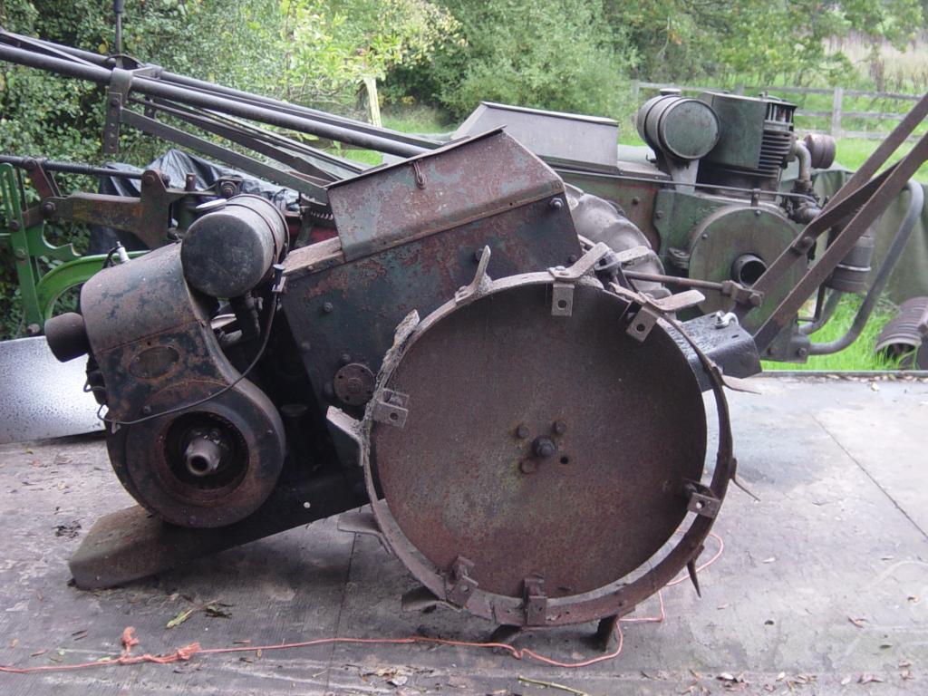
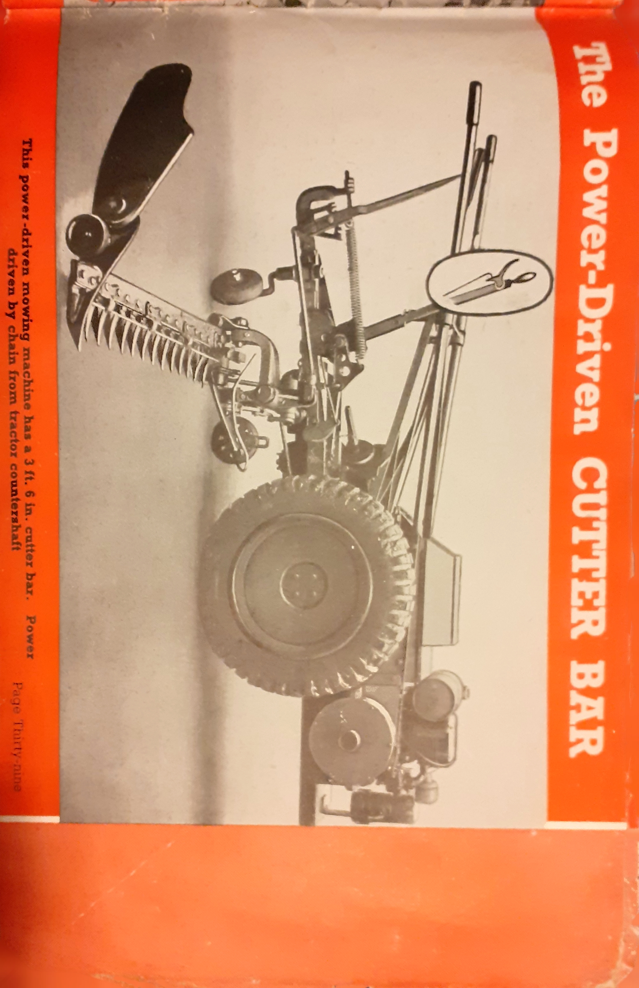
I am intrigued as to what the chain drive on that Trusty in the photo is for.December 17, 2020 at 3:13 pm #36185charlieKeymasterI can appreciate how long the transfers must be taking from the small amount of photo editing I have done eg removing barrier ropes from photos of machines at shows to make a clearer picture for inclusion in The Cultivator.
I am intrigued as to what the chain drive on that Trusty in the photo is for.December 17, 2020 at 5:48 pm #36186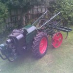 trusty-madParticipant
I am sure Geoff will correct me if I am wrong but I think the chain drive is for this. It looks just as lethal as it sounds in the description.
Attachments:
December 17, 2020 at 10:11 pm #36191trusty220KeymasterYes, you’re quite right Robert, it’s the chain drive for an Albion finger bar mower. If you look closely you can see the dog clutch for engaging/disengaging the drive on the right hand side. Normally the chain will be in motion when the countershaft is rotating, so you’re quite right in saying that it looks lethal!
Obviously people in those days knew not to put their fingers into moving things! I wouldn’t like to try to market one in today’s climate of litigation.
-
AuthorPosts

- You must be logged in to reply to this topic.