Home › Forums › The Main Forum Area › Projects › Early Trusty Rebuild
- This topic has 101 replies, 14 voices, and was last updated 4 years, 2 months ago by
 trusty220.
-
AuthorPosts
-
April 20, 2020 at 9:07 am #33915
 trusty220Keymaster
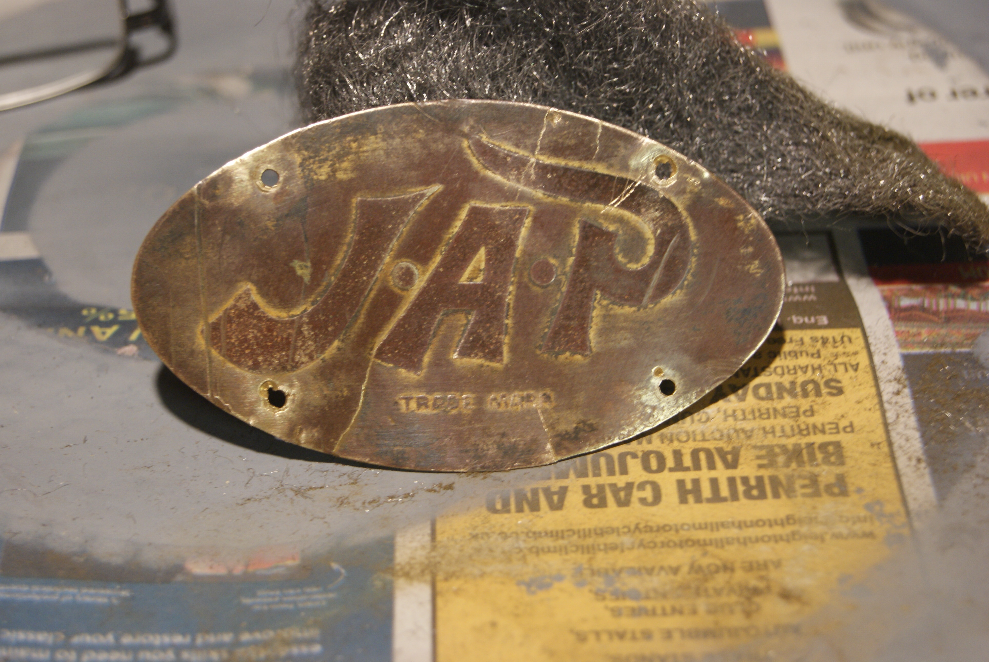
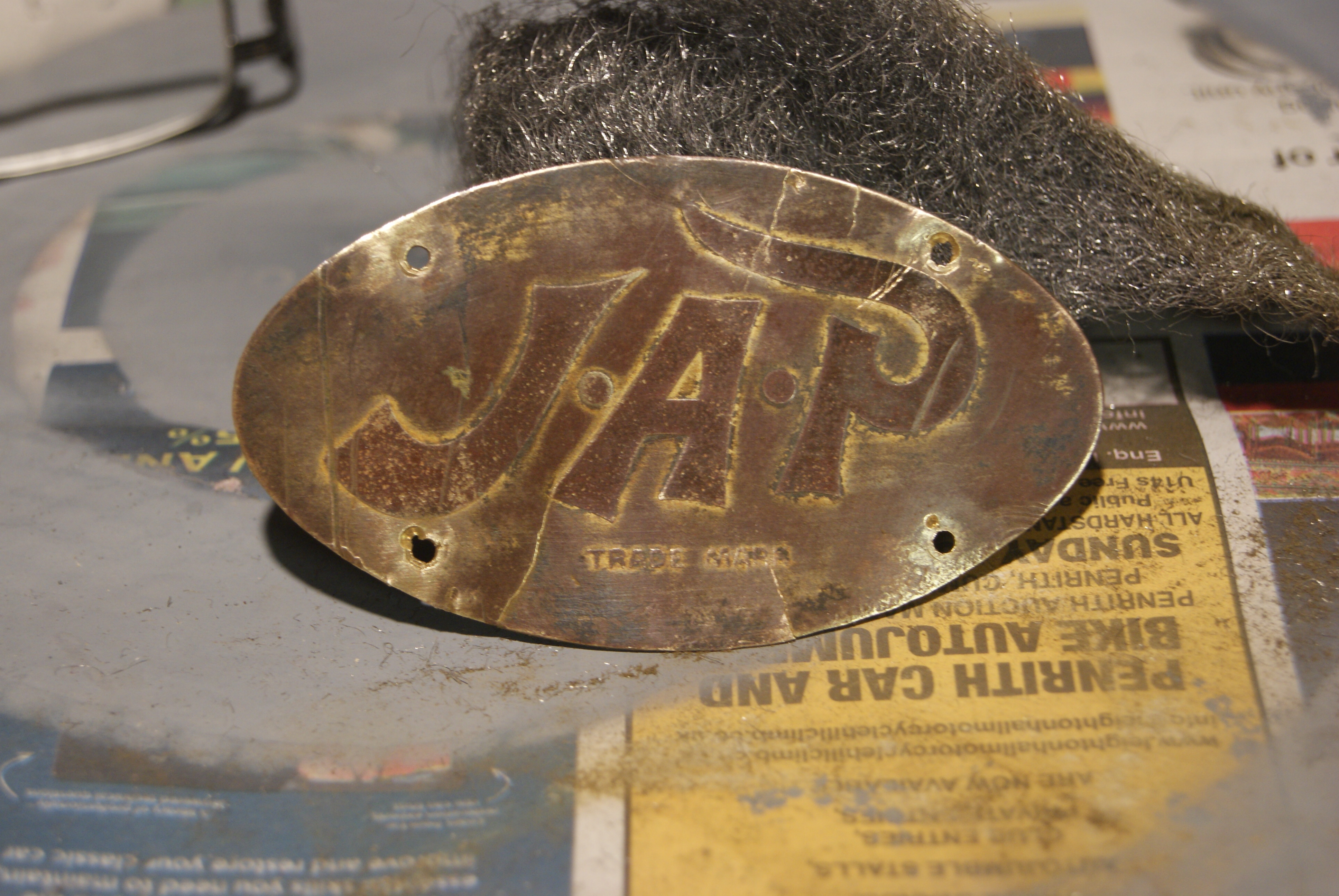
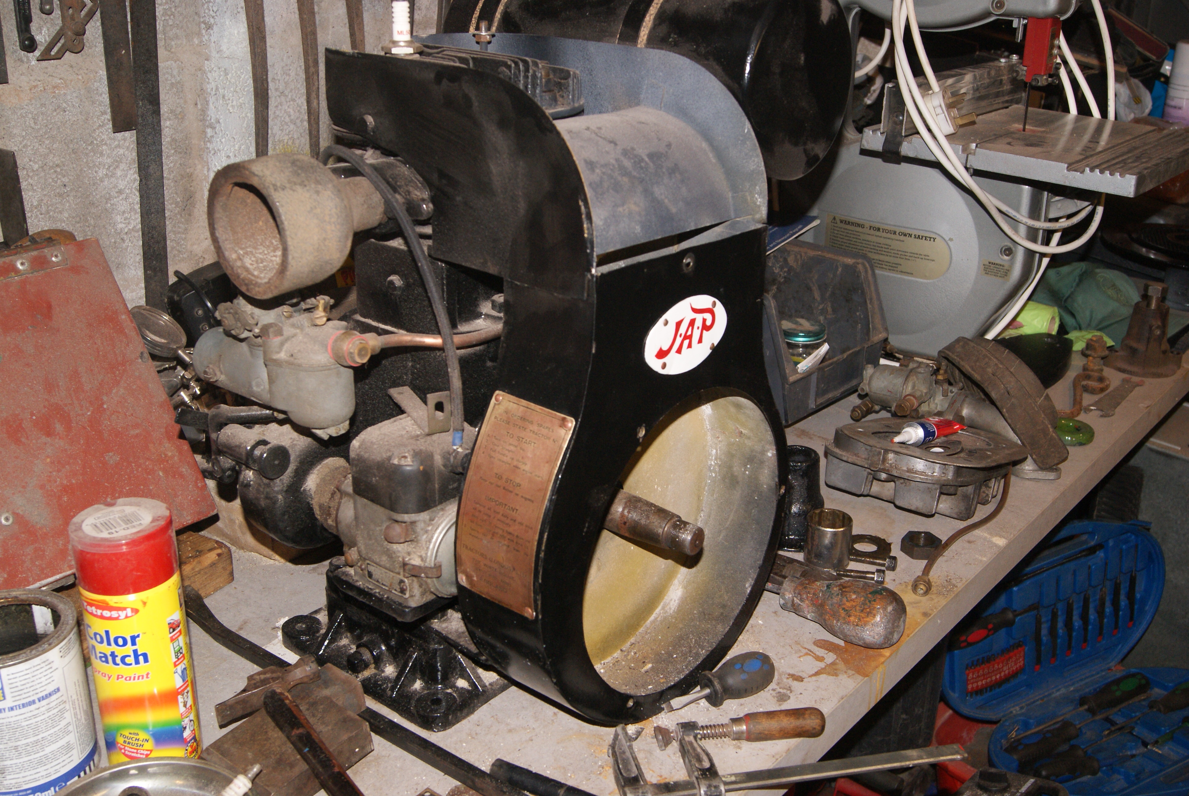
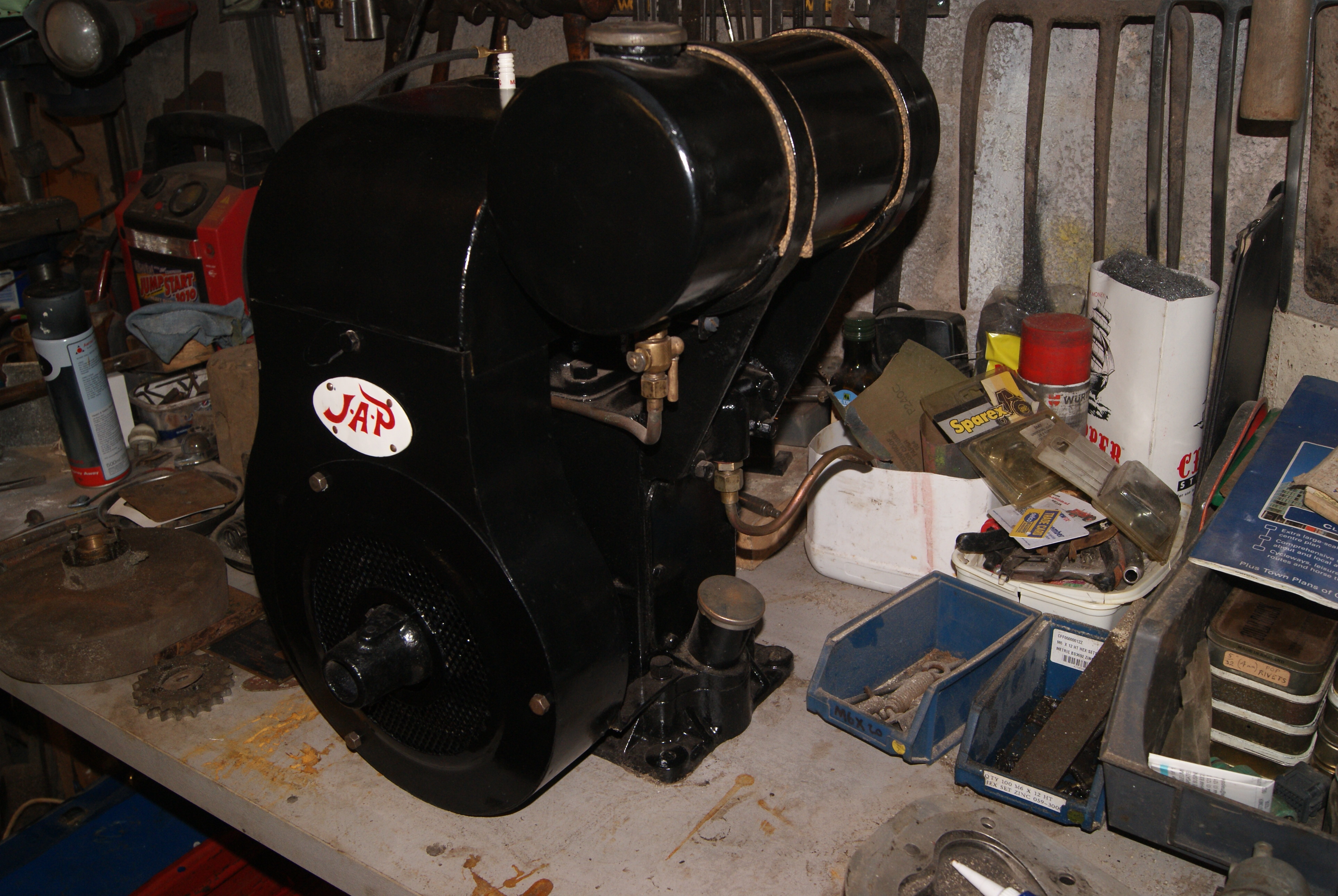
Now I’m really stating to get into the swing of this rebuild! As a challenge I thought that I’d tackle the badge on the cowling just above the flywheel- the early JAP 5’s had an oval brass plate rivetted to the cowling instead of having JAP embossed into the steel like the later ones had.
As with all older machinery they have survived much longer and been through a lot more wear than some of the younger ones and so there is usually more to repair. This is no exception. The oval brass plate was still in one piece but only just- it had cracks all over it and the rust behind it had pushed it into all sorts of stretched shapes around the rivets; still, it hadn’t been forced with a screwdriver in an attempt to steal it, so I thought it worthwhile to try to repair it.
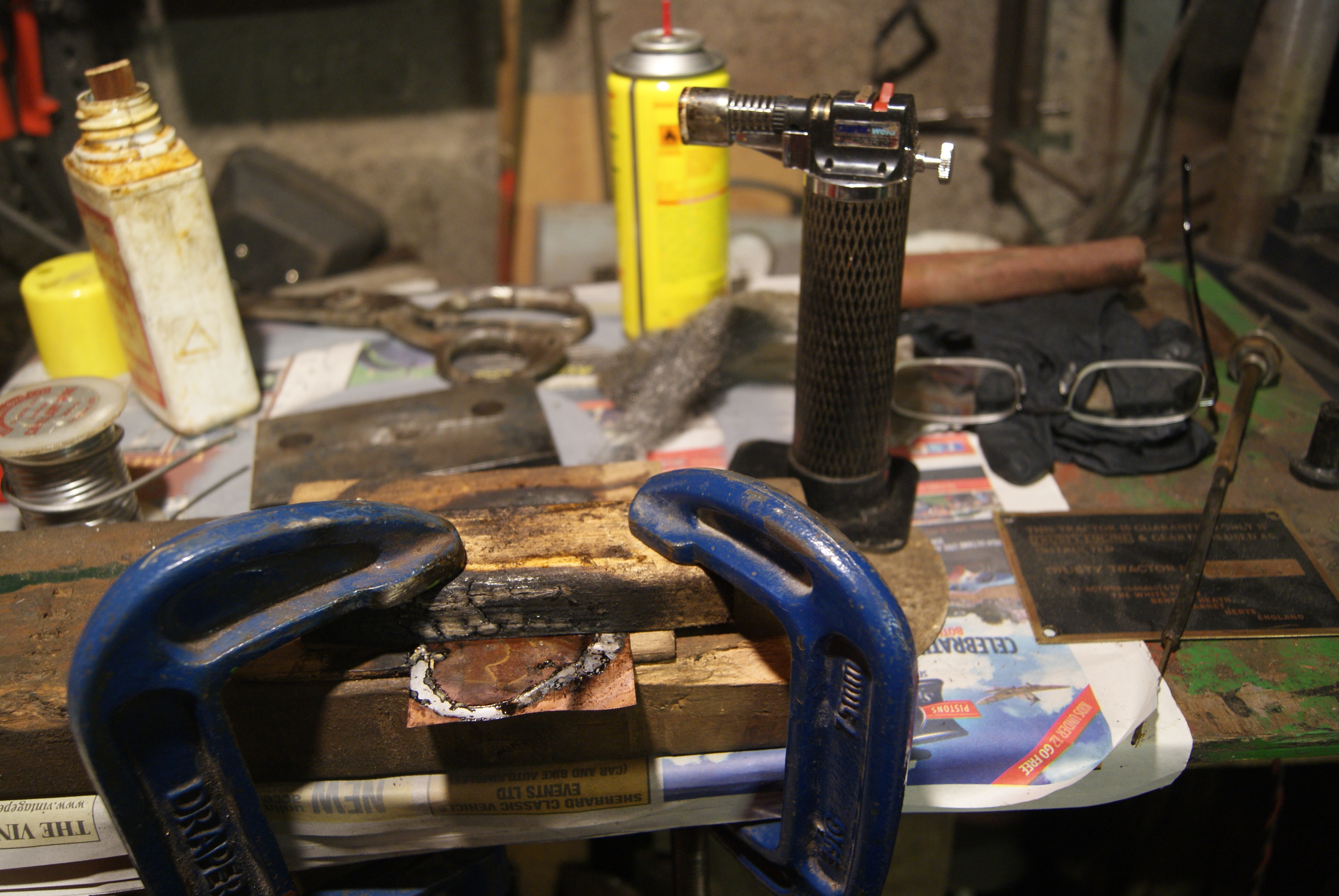
First off was to re-heat it using a little butane blow torch that I have. This will anneal it and make it more pliable, otherwise the cracks will spread once you try to work the material. I flattened it out as best as I dared on a flat anvil using a small hammer, then turned it over and spread solder thinly and evenly over the back of it using the blow torch again to get a larger area warm. The knack is quite easy once you’ve tried it a few times and you can get the solder to flow to the warmer areas using the flame of the blow torch; if the solder is too thick in places all you have to do is warm it up again and it will spread out.
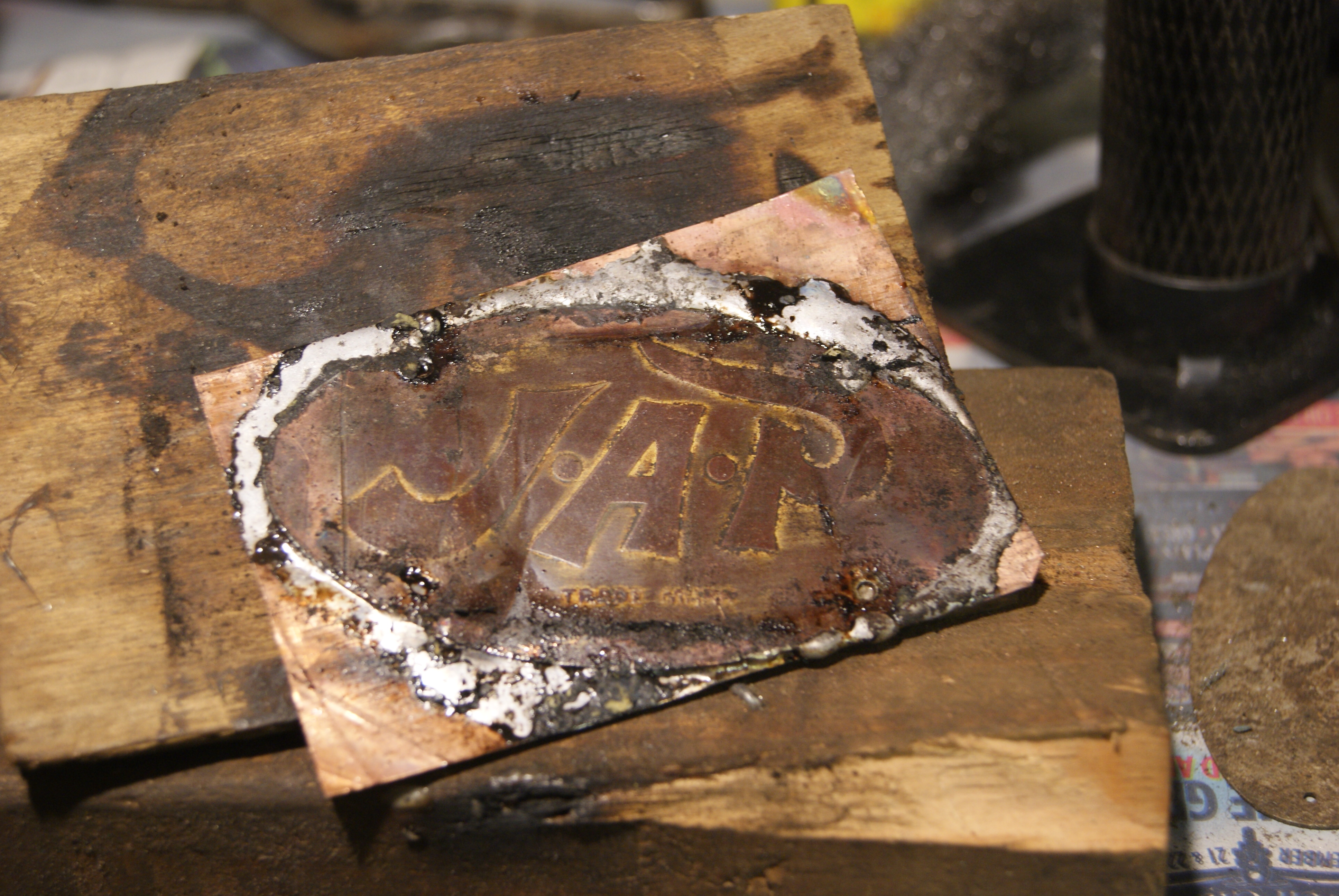
Now, here comes the clever bit- I turned it over again and pressed the soldered side against a thin sheet of copper. A flat block of wood underneath and another, narrower one clamped across the top with G-clamps made sure that there was plenty of pressure pushing the two together, then I heated the sides of the brass plate that were still exposed (that’s why I used a narrower block of wood on top, so I could still get to heat the brass and melt the solder whilst the pressure was till on).
If you’ve done it right you should see little beads of solder squeezed out of the join between the plates but if your plate is still a little wavy like mine was you will need to re-position the blocks a few times to make sure that you can get to heat all of the brass plate. Patience is the key and I found that every time I re-positioned them the two plates came that little bit closer together until the whole assembly was flat.
All you have to do then is clean it up with a file and it’s as good as new- well better, really, because it’s original!
Attachments:
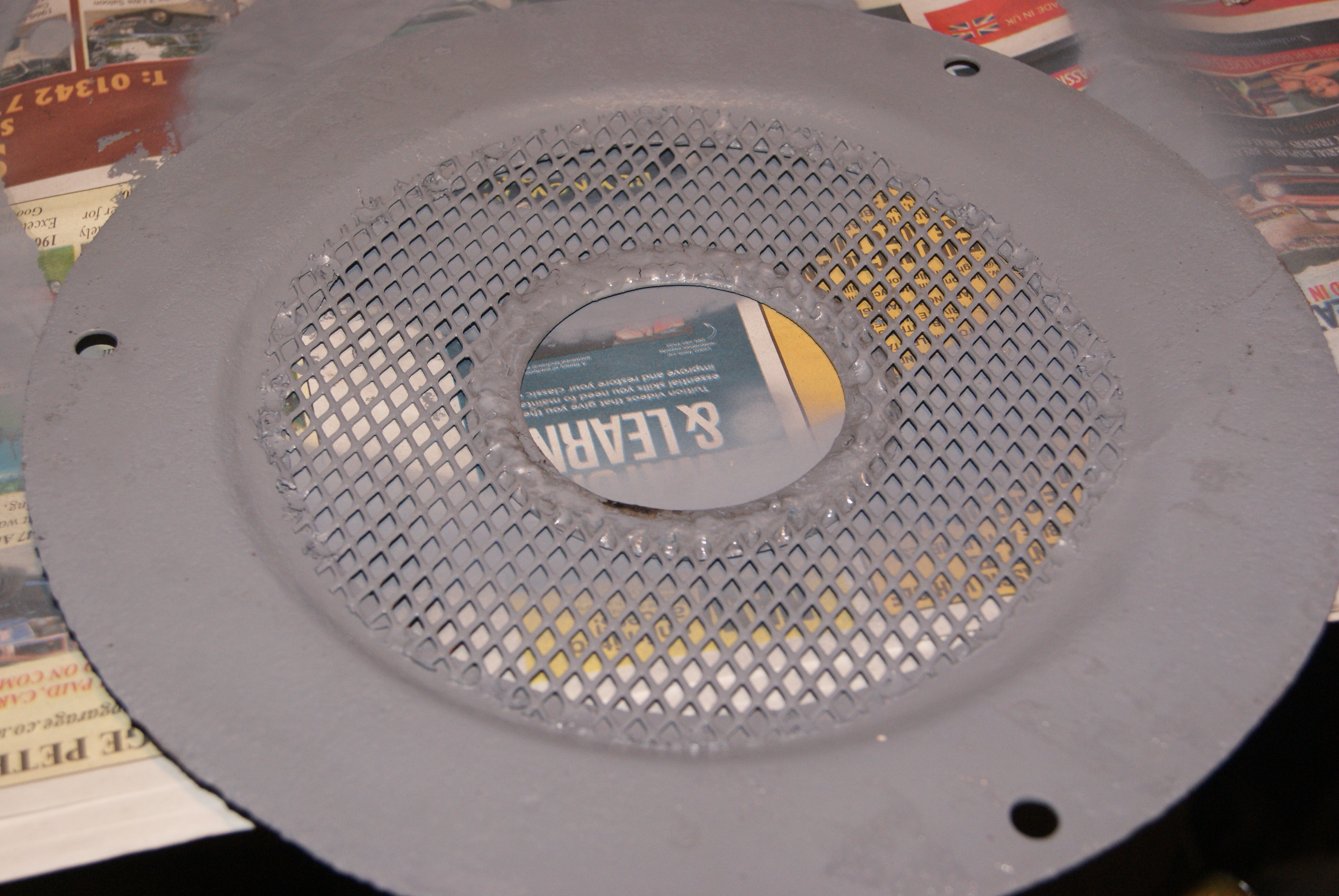
April 20, 2020 at 9:34 am #33921trusty220KeymasterAnother part that I’d put to one side was the grill for the cowling. The original outer ring was still there with pieces of expanded steel mesh welded to the back of it, but the complete centre was missing entirely and so the mesh needed replacing and a new centre around the starting dog was needed as well. Having researched it quite heavily I came to the conclusion that the centre around the starting dog was only a flat steel ring instead of the pressed dome of the later ones, so that didn’t look too difficult.
Luckily I had some mesh in stock of the right type and so I spot-welded that to the outer ring. the centre ring wasn’t so easy, though, but a little patience had one cut out with a jigsaw and filed up ready. Now- how to attach it without distorting it? the outer ring was easy because there was quite a lot of metal to support the welds, but this ring is so narrow I couldn’t guarantee a good finish without it buckling up and so the thinking cap came out again.
The solution was to use the same method as the engine plate- tin the reverse side of the plate heavily with solder, position the ring correctly on the mesh by doing a dry assembly run and marking it’s position with paint, then remove it all and put it face down on the bench. So long as the ring is in the correct position it’s then easy enough to heat the solder up and let it flow into the mesh. Just to be certain I added a little more solder to mine as well in places where it hadn’t quite flowed into the mesh all of the way, but the end result is an even spread of solder and a lovely flat steel ring in the centre of the mesh grill.
Another hurdle overcome!
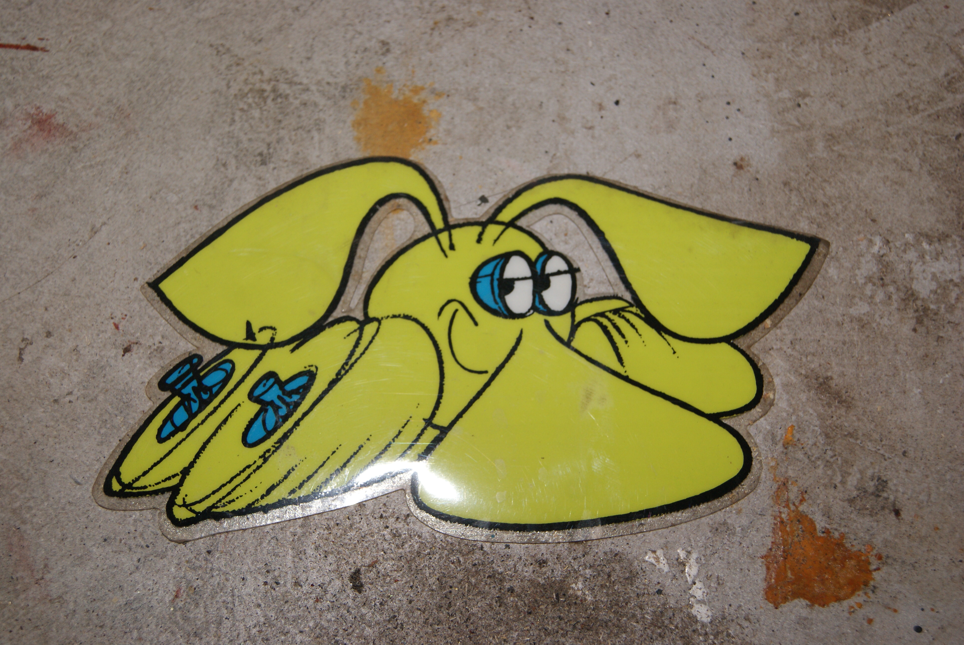
P.S. When I was hunting around for the mesh that I knew I’d put somewhere “safe” I came across the sticker of the Groundhog. When I was little my dad used to bring home loads of these from work- he used to work at Dunlop- and they were plastered all over things in my bedroom. If you don’t remember, it was a publicity drive that Dunlop did in the very early Seventies and Groundhogs were everywhere. This one was still stuck to the inside of a biscuit tin lid with some assorted junk in from my parents’ house; with a little TLC it’s going in the back window of the GT6 before too long!
Attachments:
April 20, 2020 at 7:54 pm #33929trusty220KeymasterHave you ever felt a complete fool? I bet most of you have at one time or another. It was my turn today.
Having finished the work on the JAP oval I thought that I’d paint it with etch primer as the first stage of the painting process; the original was enameled with a white background and red lettering but the paint will not stick unless the proper primer is used on the brass plate. When I found the can of etch primer, hiding behind it was an aerosol can of white radiator paint- great, that’s just the ticket and it’s bound to be more hard wearing than normal enamel I thought.
When the time came to apply the white paint I rattled the can up and down, pressed the nozzle and….nothing. The last time I used the can must have been four years ago, so I thought the nozzle must be blocked. I blew through it but could not find a blockage, so I thought the hardened paint must be in the can itself. I found a piece of welding wire and started poking about inside the top.
The last thing I remember before everything went white was a very loud hiss and a very wet feeling all up the side of my face. Not daring to move, I shouted for help to Mrs. Geoff who came running. Now, women can be very cruel at times and this was no exception. All she could do was to sit on the floor gasping for breath with tears streaming down her face and every now and again exploded with a burst of laughter. Handing me a mirror, I took off my reading glasses and looked- what stared back at me was something like a cross between The Phantom of the Opera and The Lone Ranger. Being special radiator paint we had no idea what solvent to use, but meths seemed to work to a certain extent whilst it was still wet; now that it’s dry I don’t think dynamite would shift it!
Oh well, lesson learnt. It was a good job I had my reading glasses on, and if you’re on club committee don’t expect a Skype meeting in the near future.
April 20, 2020 at 8:35 pm #33930ted20
Participantwhat no picture to cheer us up ? Dave
April 22, 2020 at 11:12 am #33936trusty220KeymasterI think your imagination should be sufficient for now, Dave, my face isn’t a pretty sight on the best of days! Anyway, I can now vouch for the quality of Plastikote Gloss White Radiator Paint in aerosol cans because it resists all attempts to remove it! It’s even in my right ear (so Mrs. Geoff tells me)!
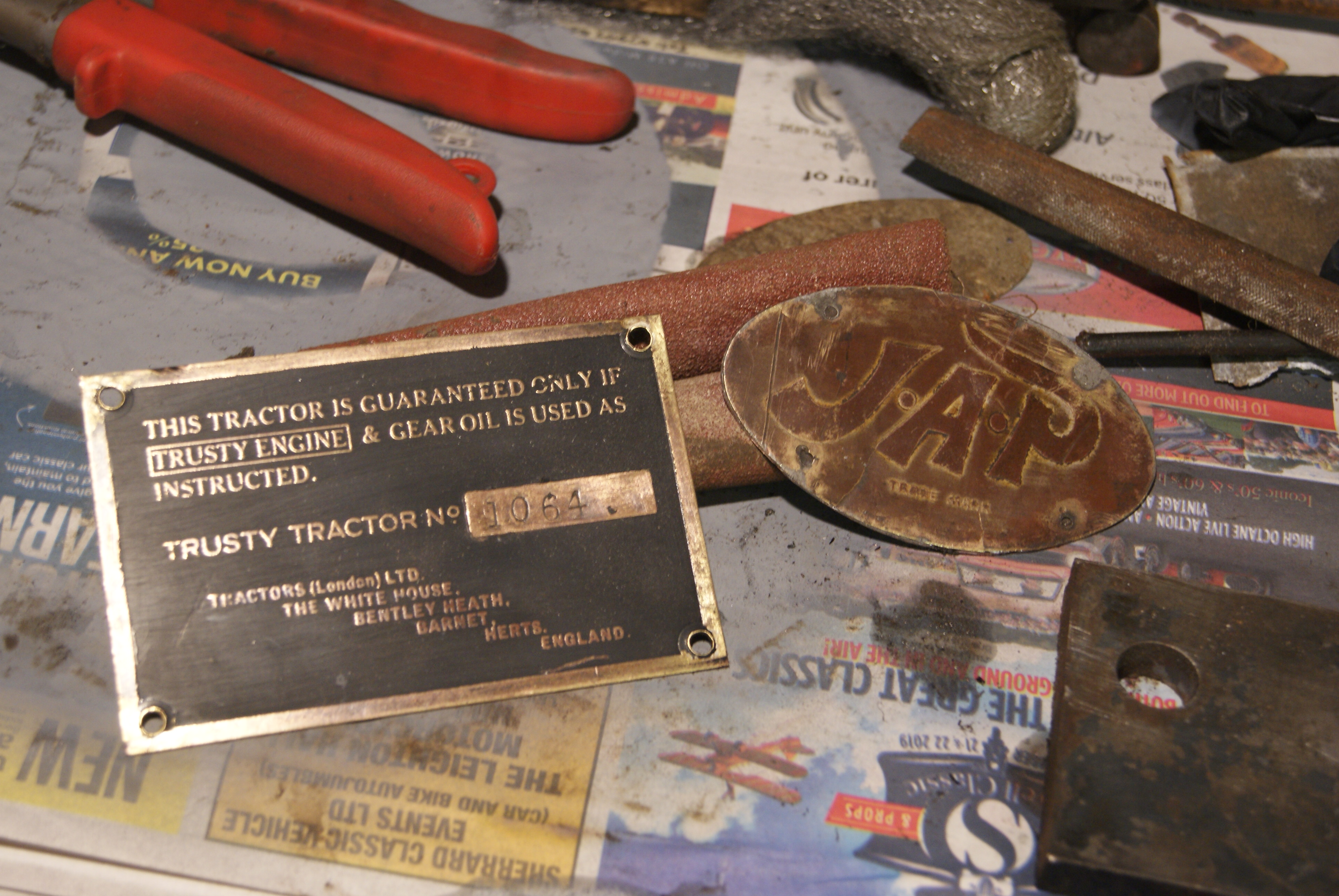
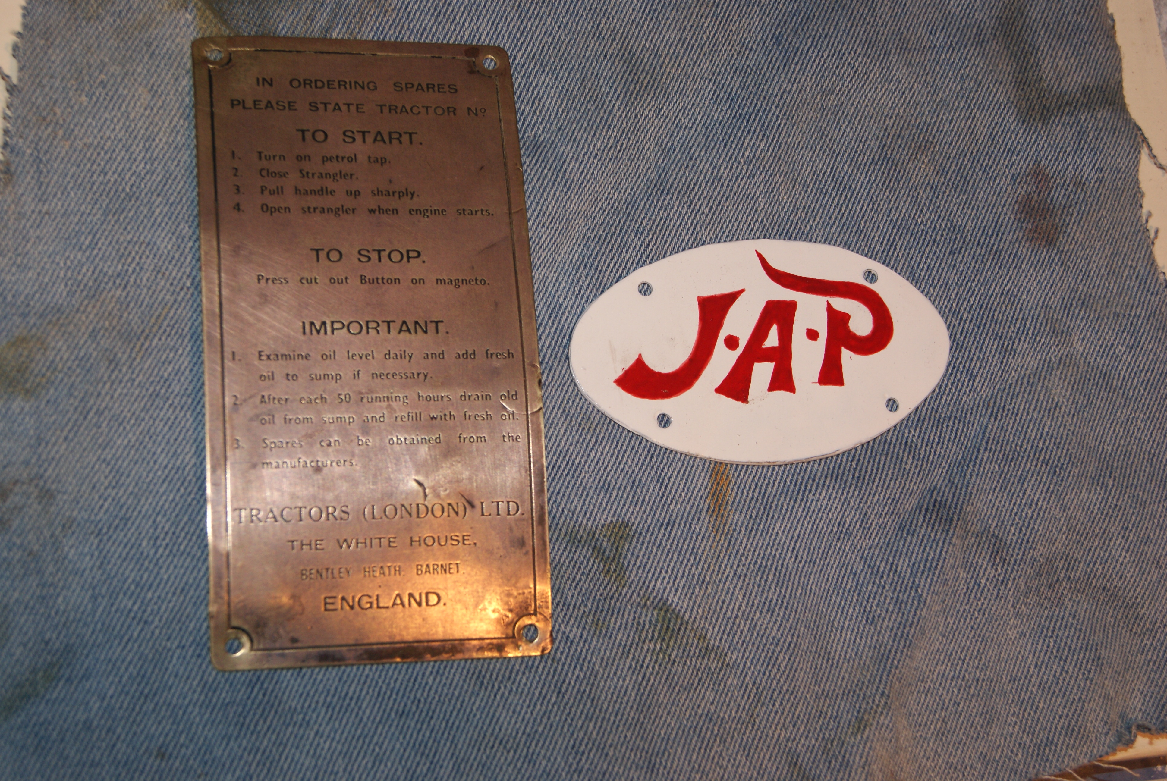
Onwards with the rebuild- now that I’ve got the paint can working I sprayed a generous coat of white onto the etch primer and left it in the sun for a day. Next day I picked out the letters in red enamel (I’m not going to use aerosol cans for a bit) with a very fine brush. It seems to have worked out quite well, but the words “Trade Mark” underneath the main letters were too small to attempt. The embossing for the large letters wasn’t deep enough to try the trick with the wire wool, so I discounted that method before I started.
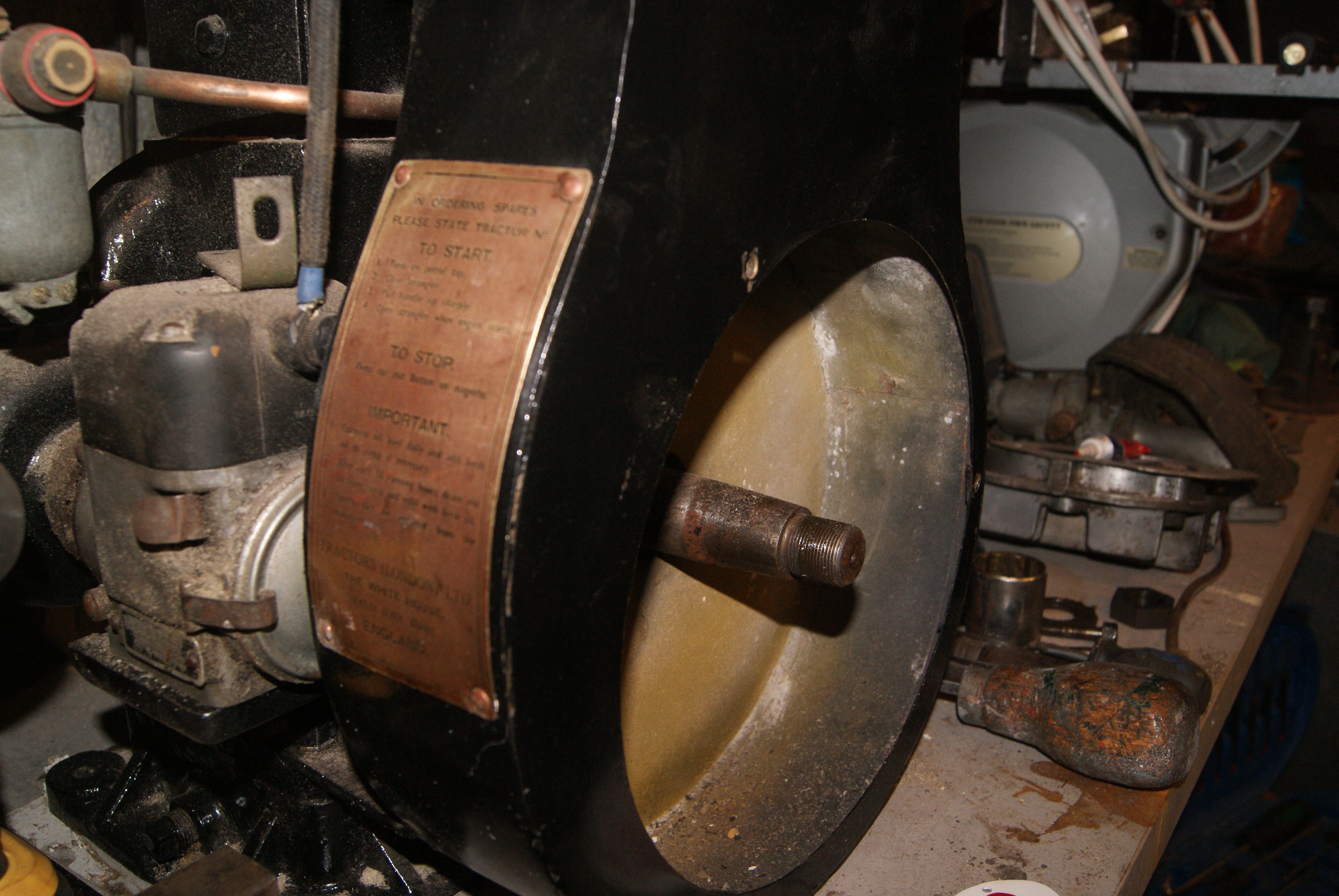
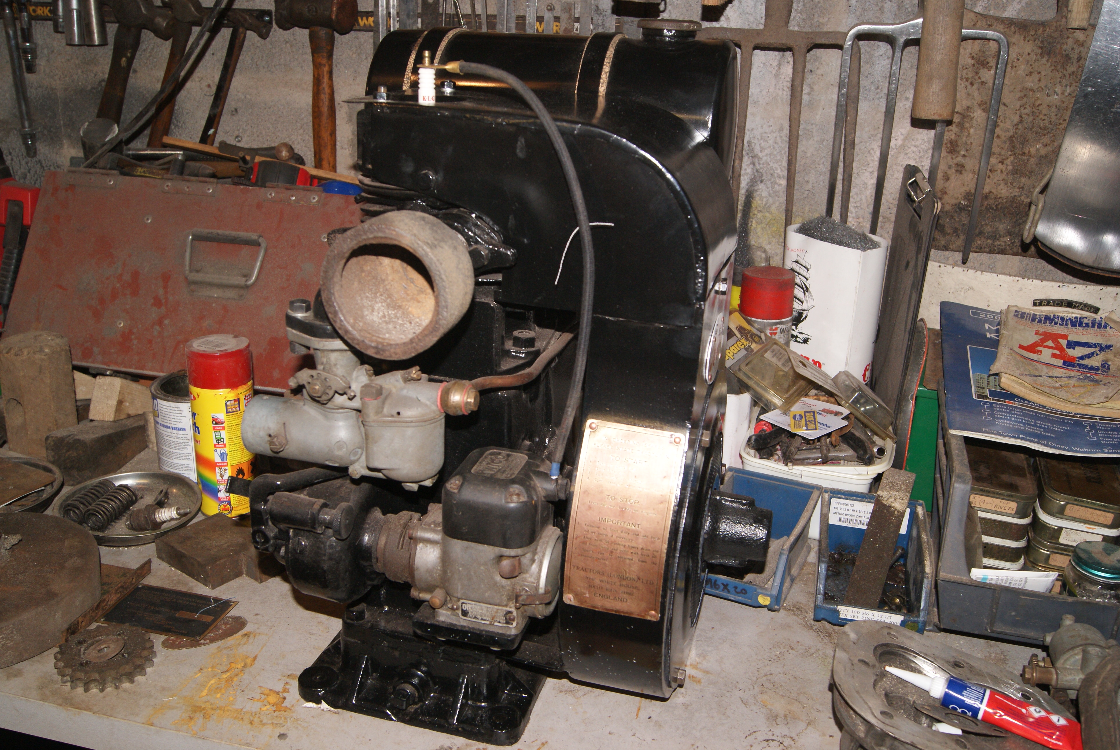
The other plate for this engine is the one that appears on the front of the cowling next to the magneto. Originally it would have had a similar plate added by JAP at their Tottenham works, but the cunning people at Tractors (London) Ltd. saw an opportunity to make more money by selling engine parts for their Trusty tractors; they used to remove the manufacturer’s plate and substitute it with their own. The two were identical apart from the last few lines which asked tractor owners to buy parts from Tractors (London) Ltd.- the original plate had J.A.Prestwich’s contact details in Tottenham.
The plate is made from brass with letters etched into it this time, so a quick go with the black spray can (I knew this one worked!) had the plate painted completely black all over. The wire wool rubbed off all of the paint on the flat surfaces leaving the letters picked out in black.
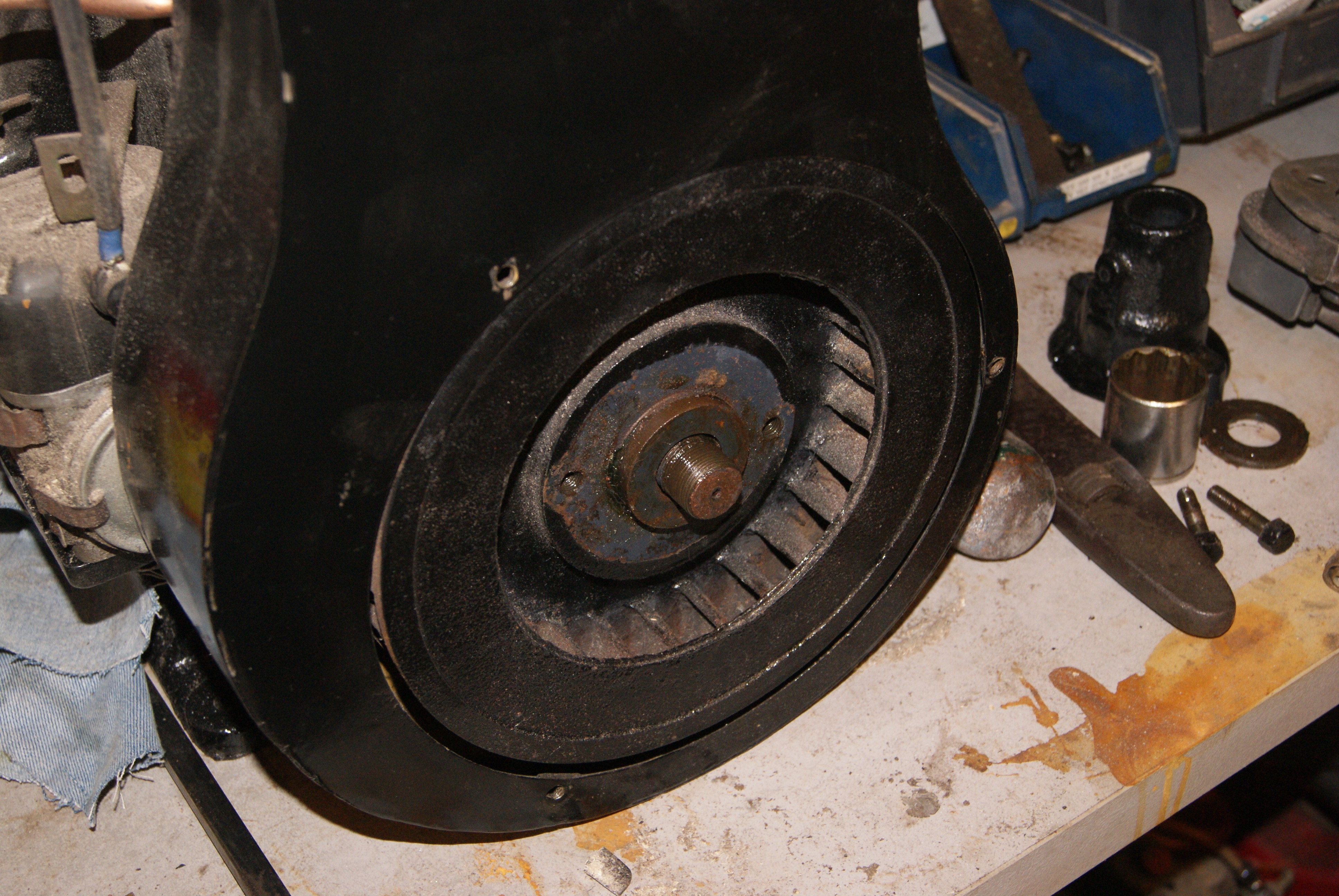
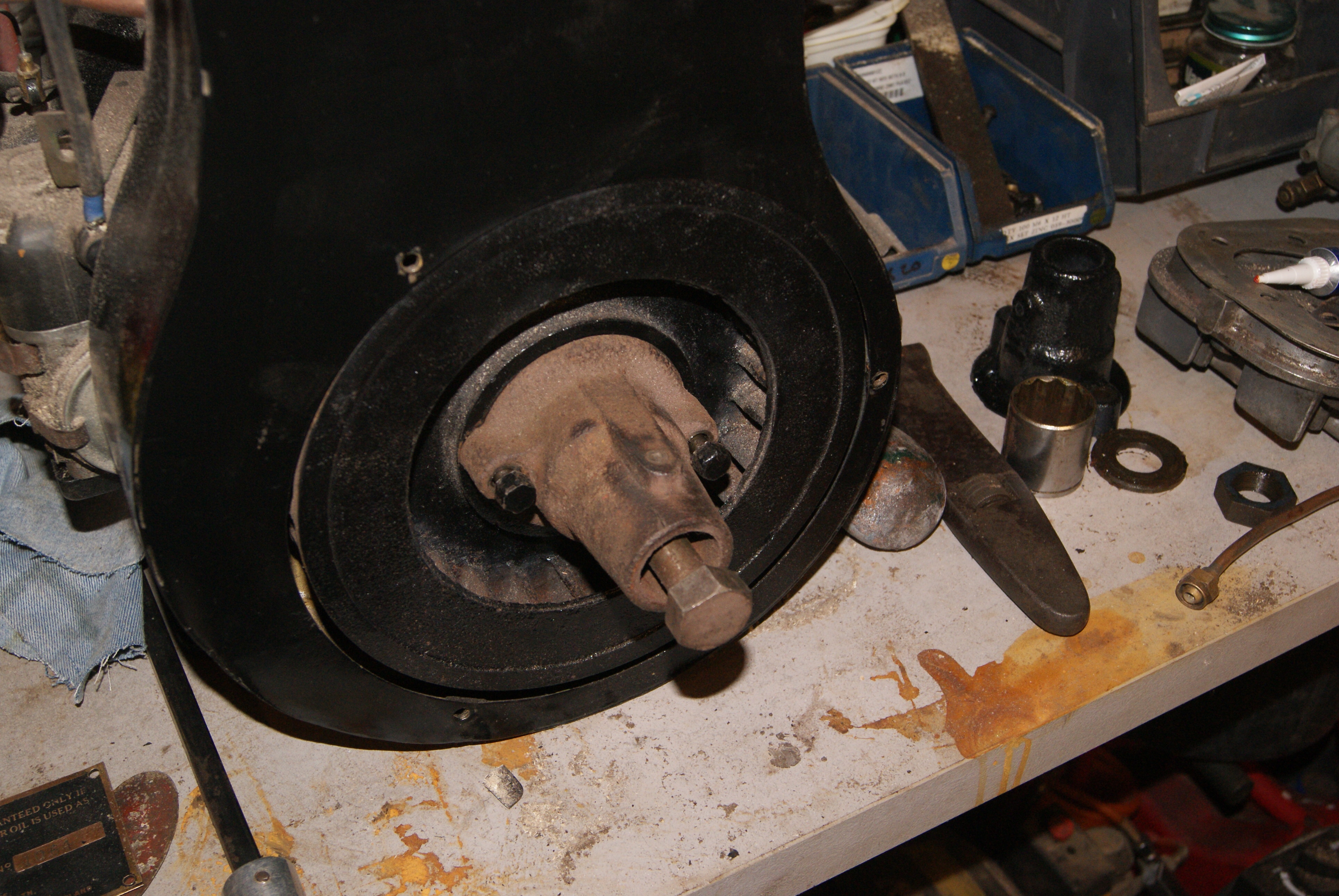
It only left the job of rivetting these plates back onto the cowling and the engine could be put aside for the time being. I found some copper rivets which would do the job well, being both soft and the right diameter, and so the flywheel had to come off again to give me access to the inside of the cowling to round the ends of the rivets over.
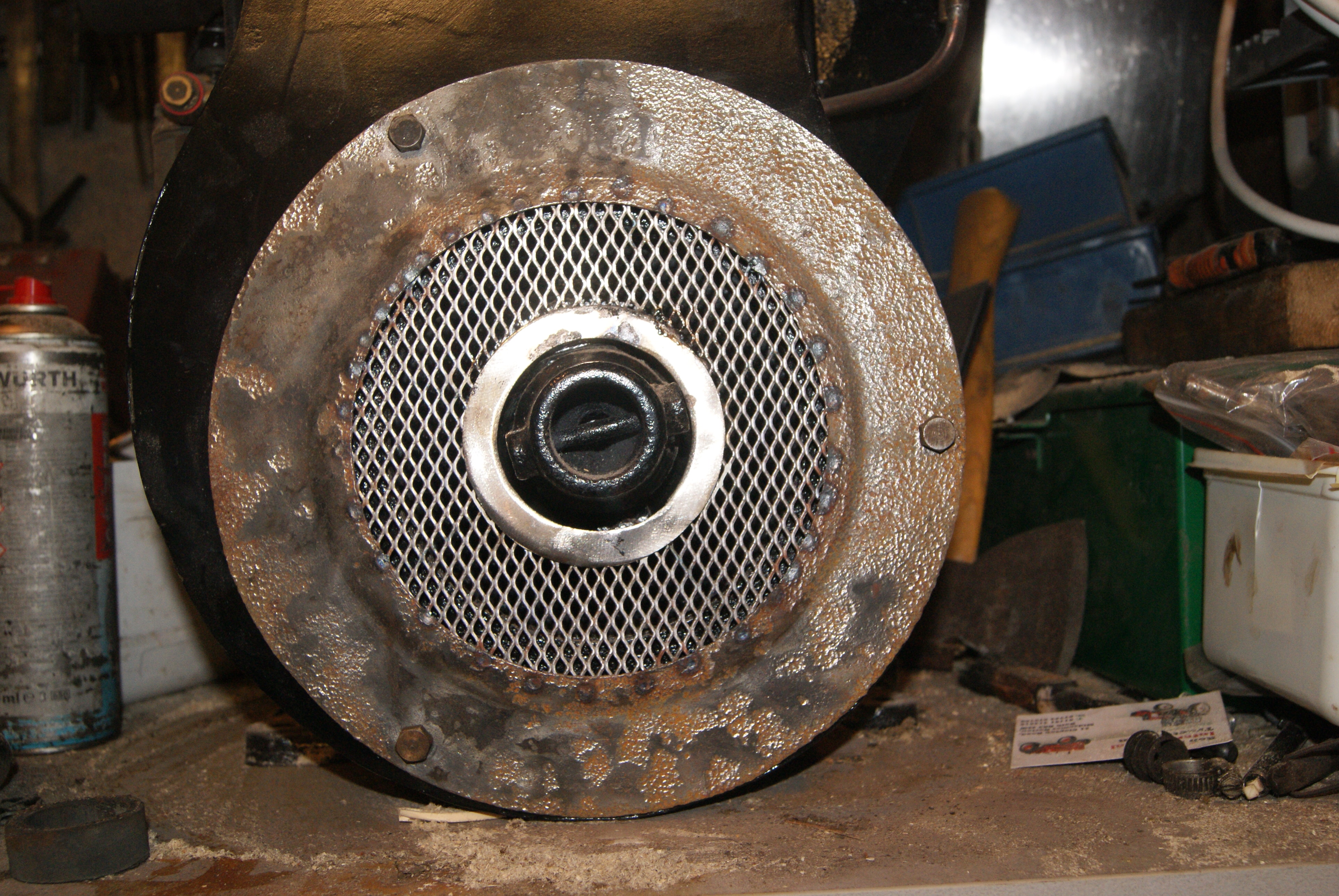
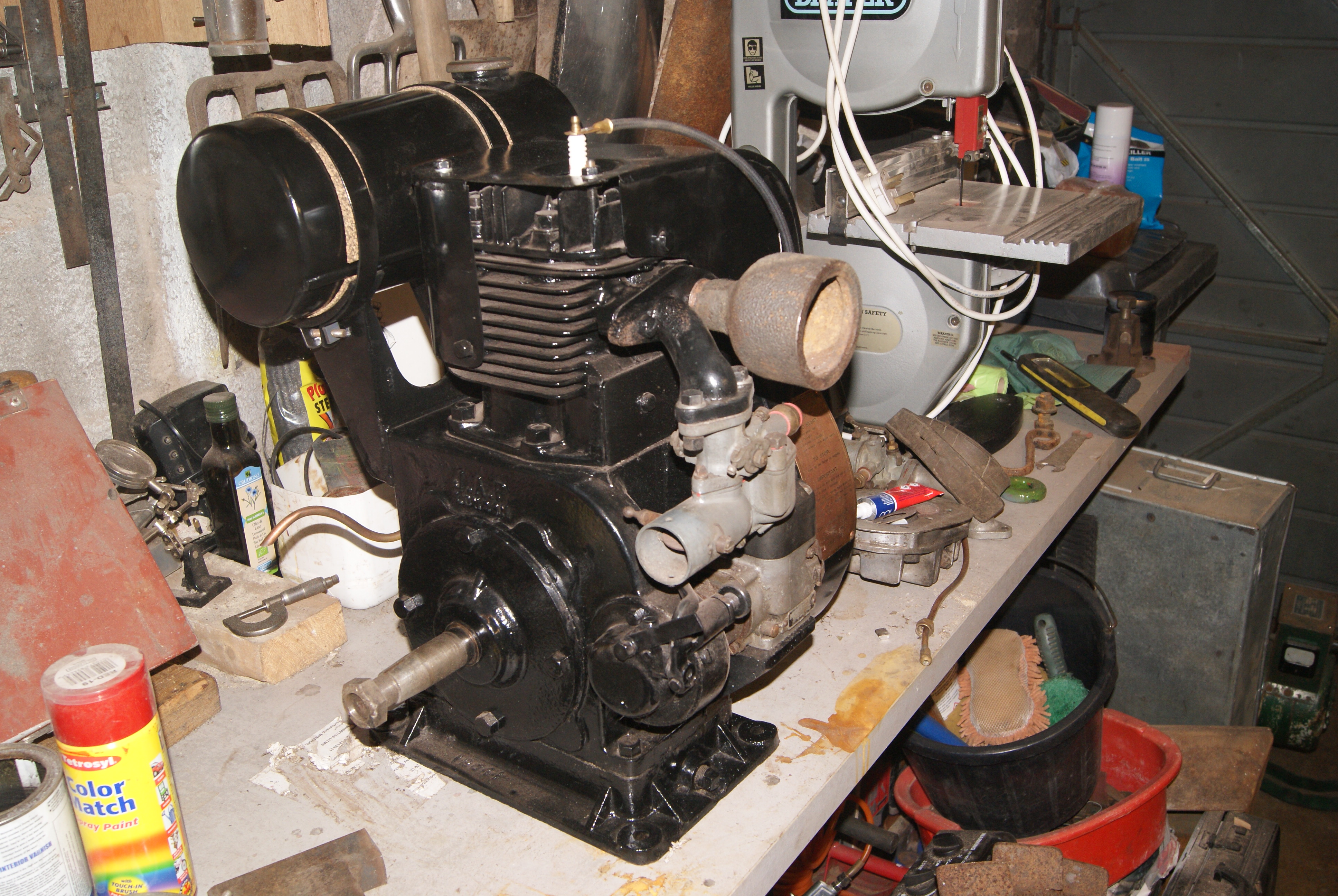
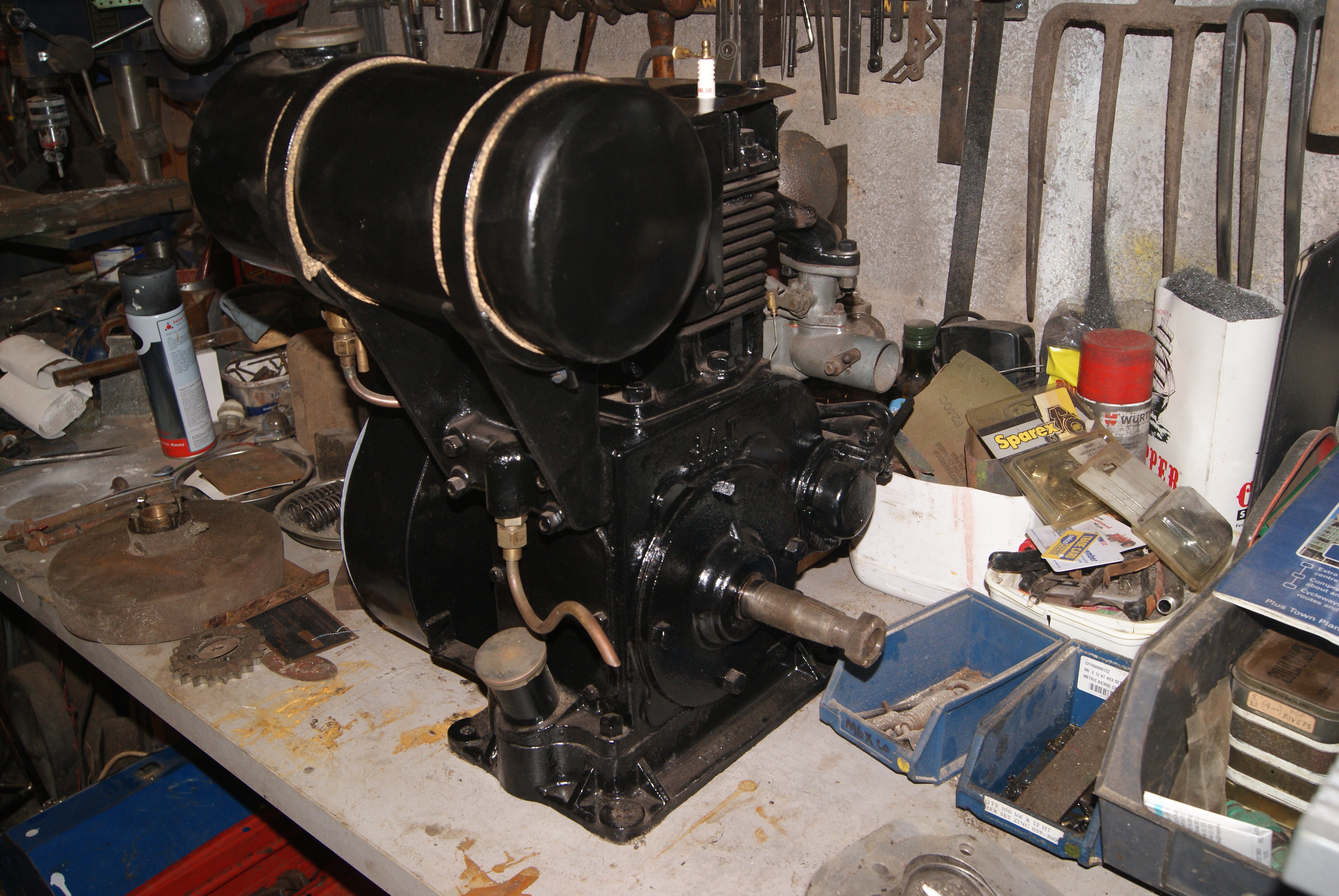
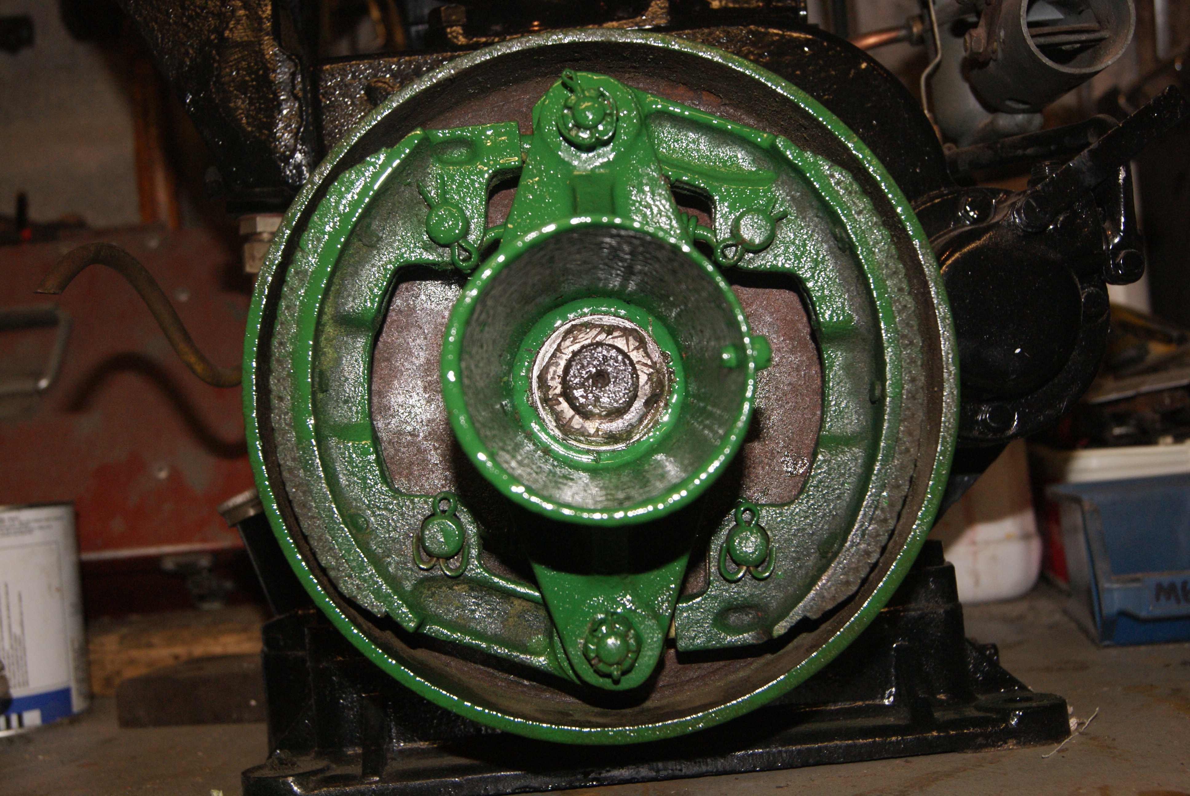
This is an early JAP 5 engine which has a very different cowling to most. The cowling continues across the back of the flywheel making it impossible to remove the cowling without taking off the flywheel- later JAP’s were modified so that the cowling will come off more easily and leaving the flywheel in place. The JAP 5 and JAP 6 engines are well engineered and incorporate their own flywheel puller to help the job along. If you look in the centre of the starter dog where you fit the starter handle there is a Whitworth thread through the centre of it; all you need to do is to remove the round bar that the starter engages with and find a bolt to fit down the centre. You will need to take the starter dog off to slacken the flywheel bolt underneath, but once you’ve done that you fit the starter back on and wind the centre bolt in until it bottoms on the end of the crankshaft. If it won’t shift by pressure alone on the bolt, give the bolt head a sharp tap with a copper mallet whilst it’s under pressure and that should be sufficient to pull the flywheel off it’s tapered seat on the cranshaft.
All that remained then was to drill a few holes and rivet the plates on, then re-assemble it all and stand back! During the rivetting process I did discover the way to remove the white paint- I managed to chip a little with the hammer whilst rivetting, but there’s no way I’m going all round my face with a hammer to get the rest off!
Enjoy the photo’s.
Attachments:
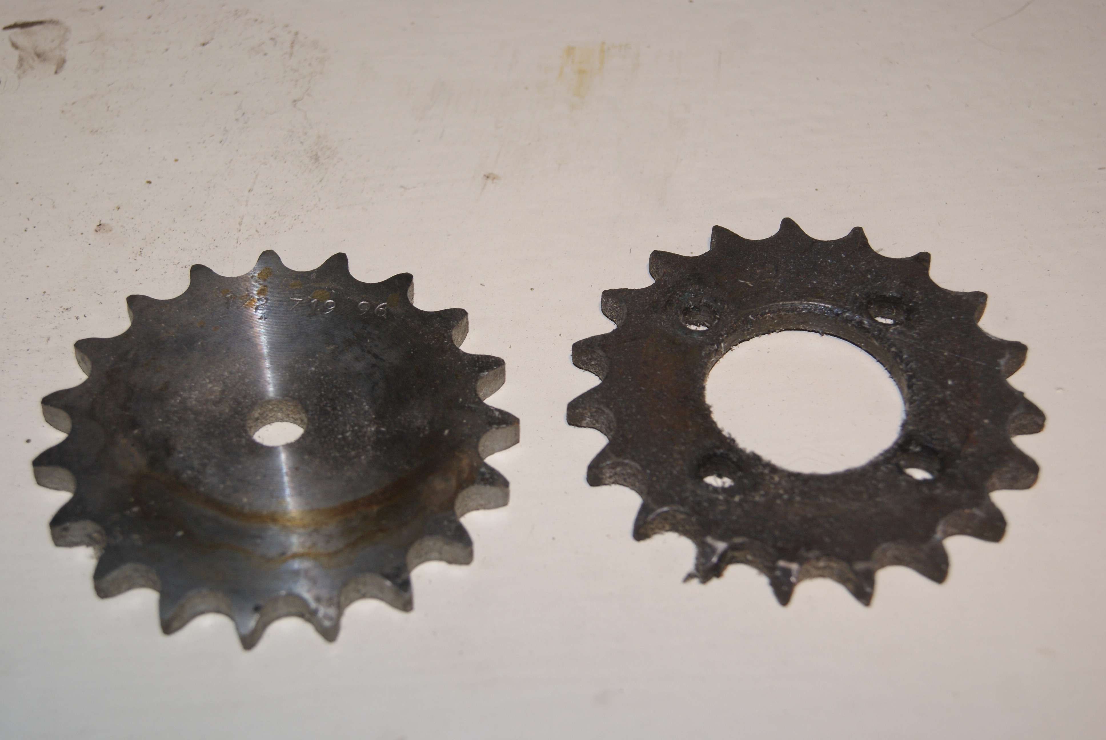
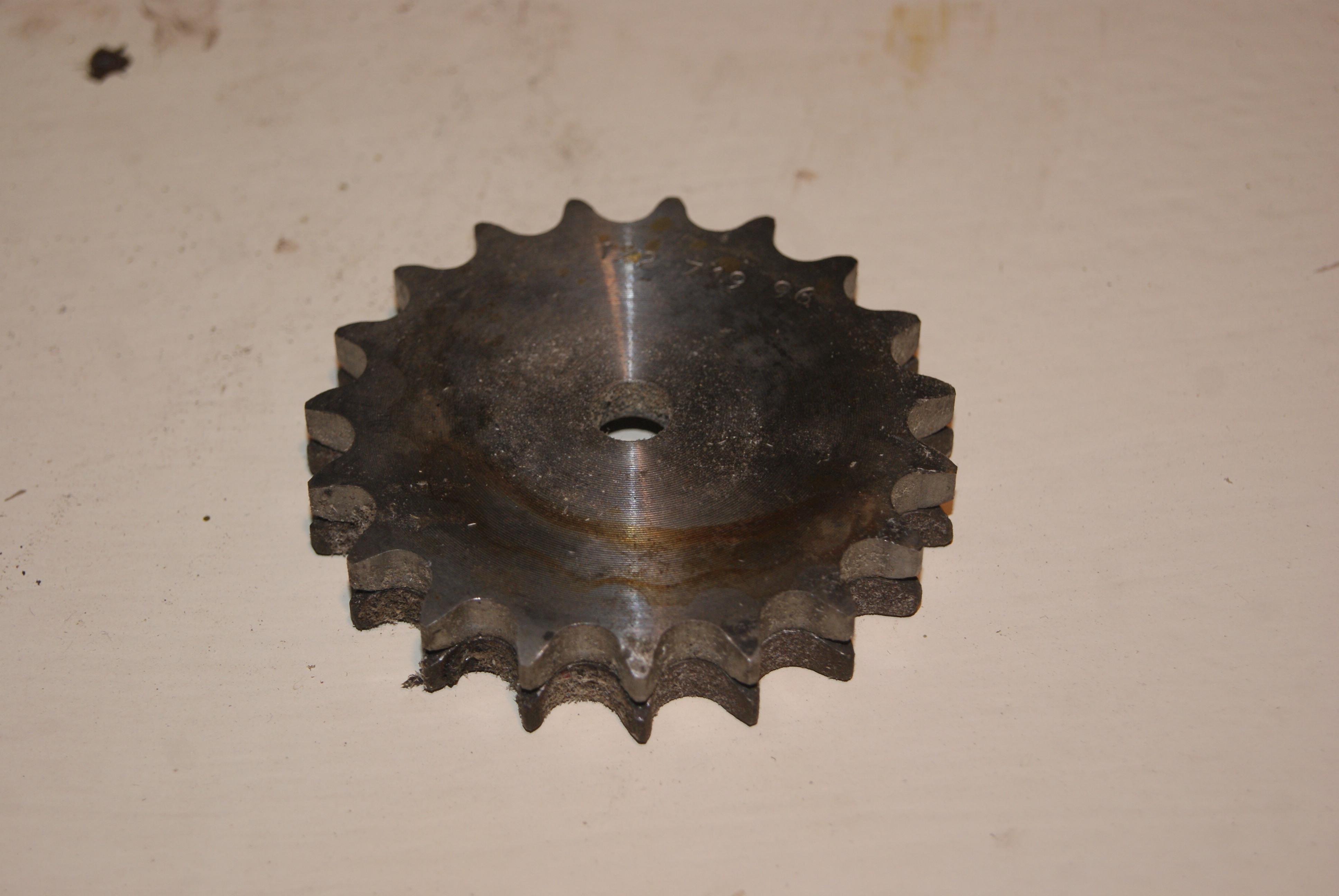
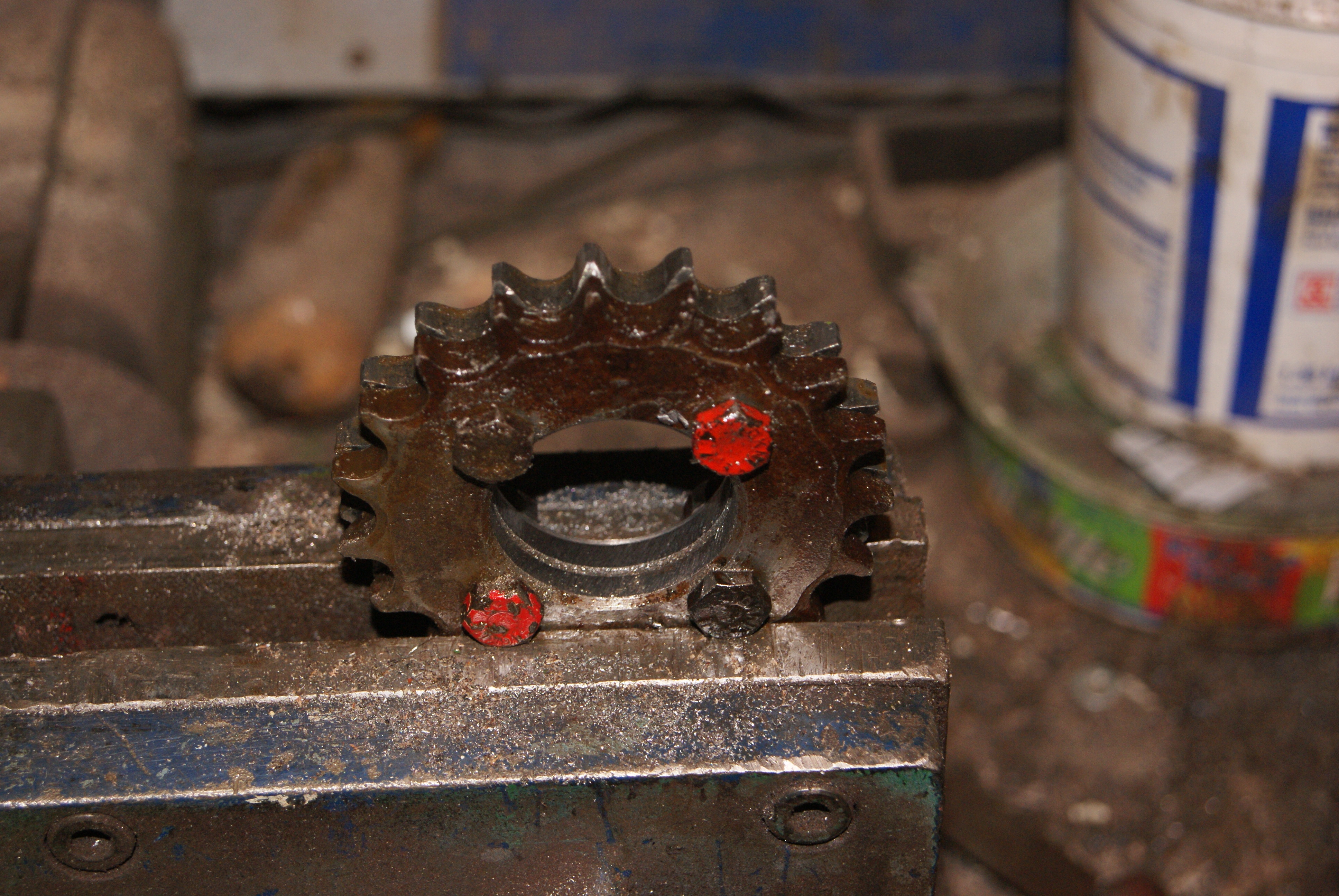
April 22, 2020 at 11:26 am #33946trusty220KeymasterNow, the next problem to overcome- I can’t fit the clutch until I’ve sorted out the chain sprocket on the clutch drum. Normally I would just mount it in the lathe and turn the centre out to the diameter that is needed to clear the centre bush, but everything is packed away in storage so I need to find a simple way of doing it without using machine tools.
If I clamp the two together I can drill out the four securing bolts using the old one as a template, but how to enlarge the centre? I’m stumped at the moment, anyone got any ideas?
Attachments:
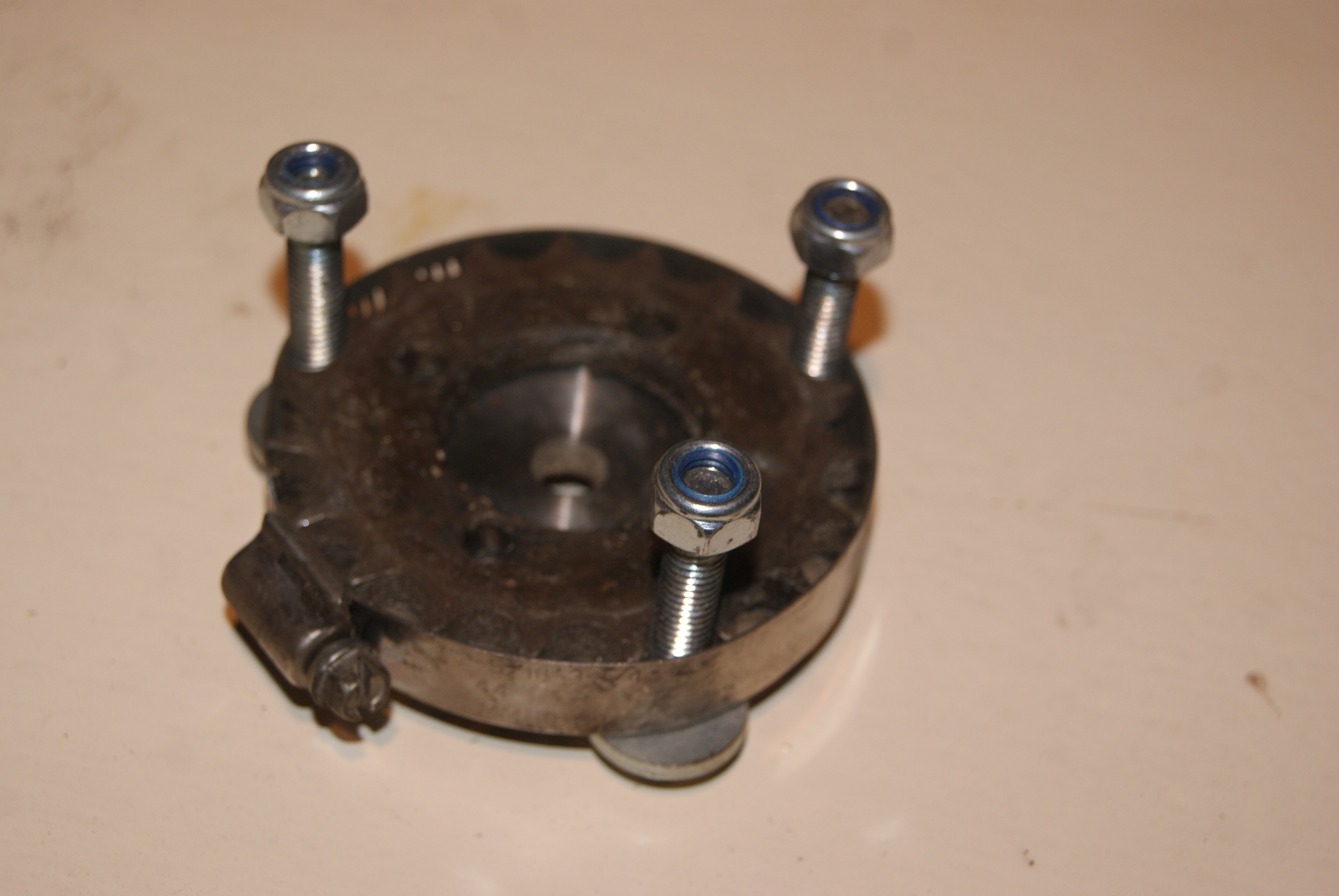
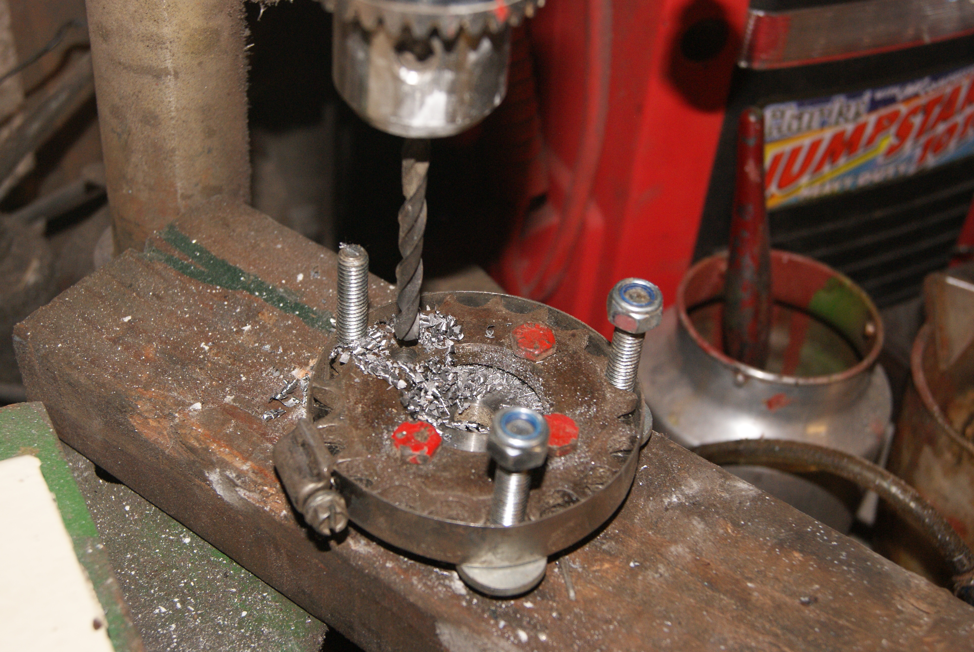
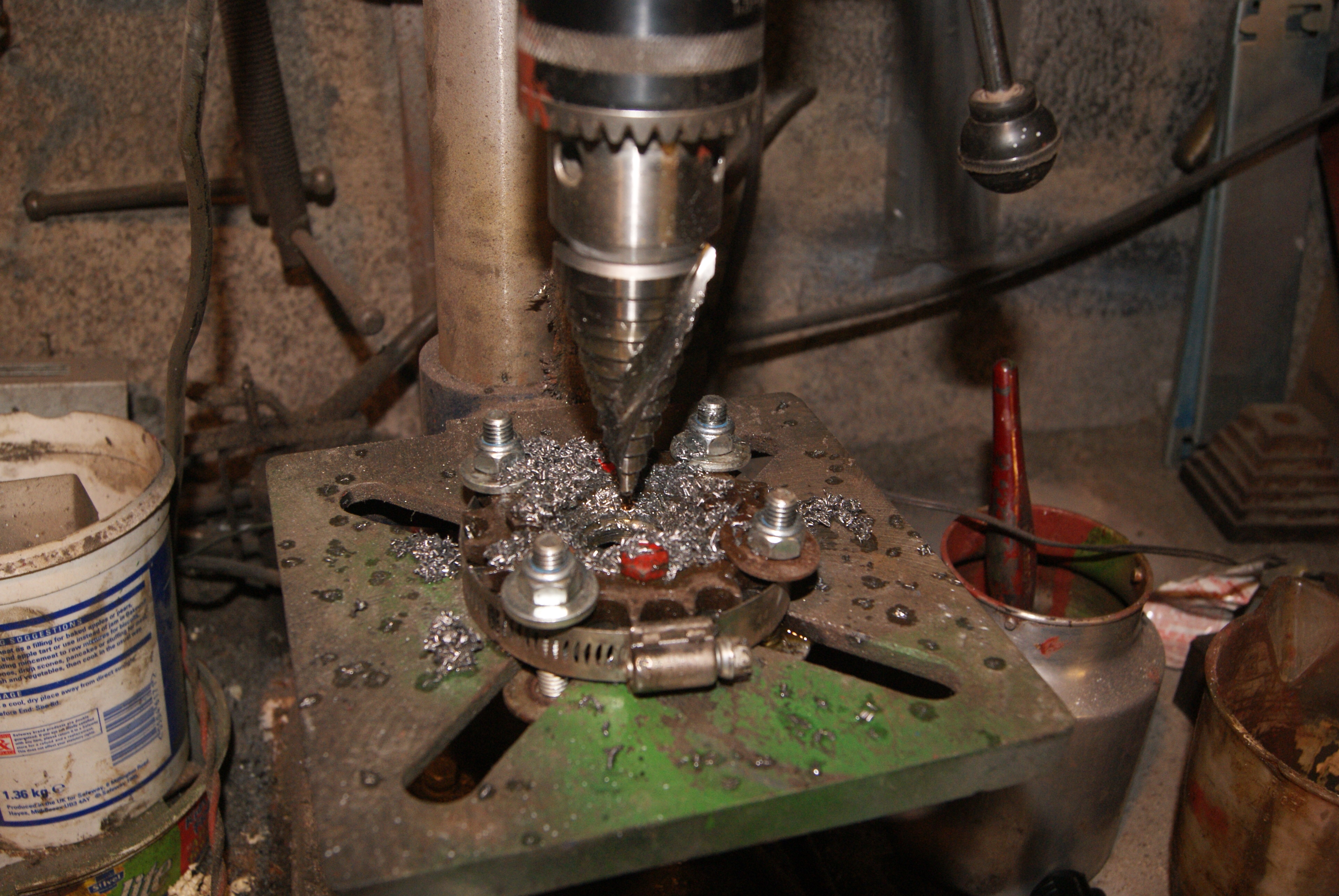
April 22, 2020 at 1:45 pm #33952trusty220KeymasterI’ve had a few ideas and progressed the problem slightly as you will see from the pictures.
In order to line the two sprockets up exactly I hit on the idea of using three 5/16″ bolts spaced equally around the rim. This uses the base of the tooth profile (which will not wear as much as the teeth do) and so is much more accurate. To force the bolts into contact with the base of each tooth I then used a jubilee clip and wound it up tight, forcing all of the bolts to push towards the centre of the sprocket. This had the desired effect of lining the two sprockets exactly so that I could use the original to drill four 1/4″ holes which locate the holding-down bolts when it’s fitted to the clutch drum.
Now I’m stuck again; how do I make the 1 3/8″ diameter hole in the middle? Help!!
Attachments:
April 23, 2020 at 8:14 am #33956 charlieKeymaster
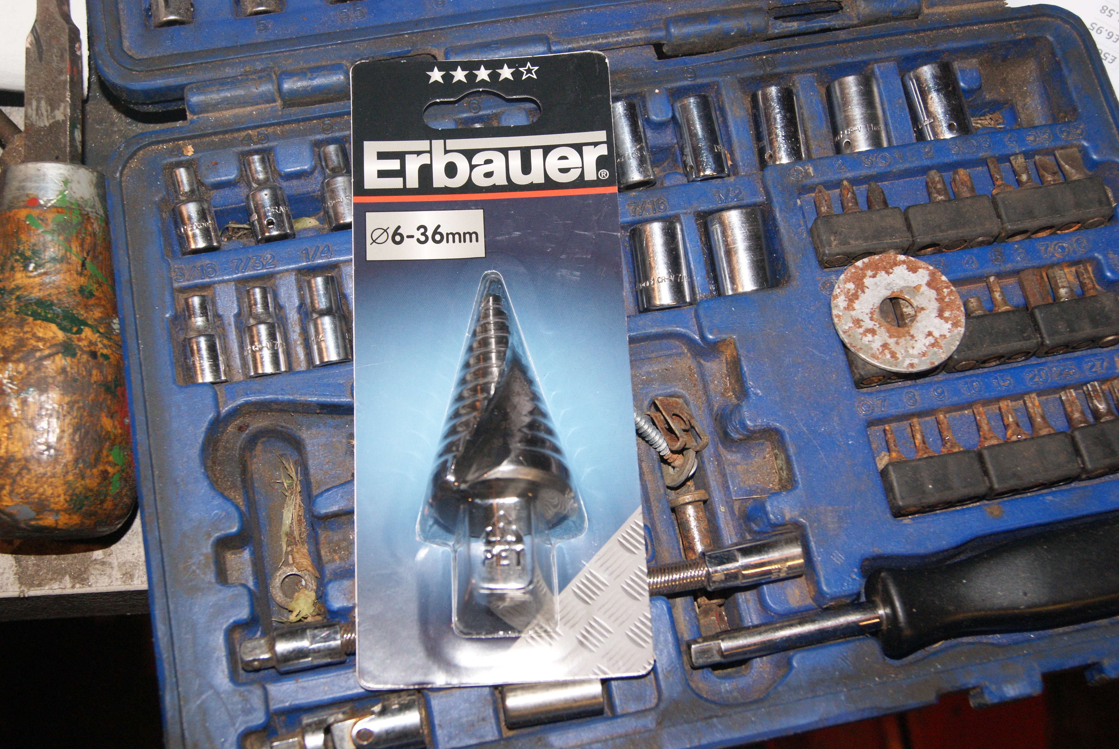
Making good progress. Would a step drill be up to the job of taking out the centre hole?
Reading about the tactic of changing engine plate so customers went to Tractors (London) for spare parts was it the same for oil, If I remember they plate said use Trusty oil, Vigzol.April 23, 2020 at 6:28 pm #33985trusty220KeymasterYou obviously had the same thought as me, Charlie. I was trying to track one down last night and eventually found one in the Screwfix catalogue that looked like it might be man enough for the job. Paid for it on line and was waiting in the queue at 8.30 this morning!
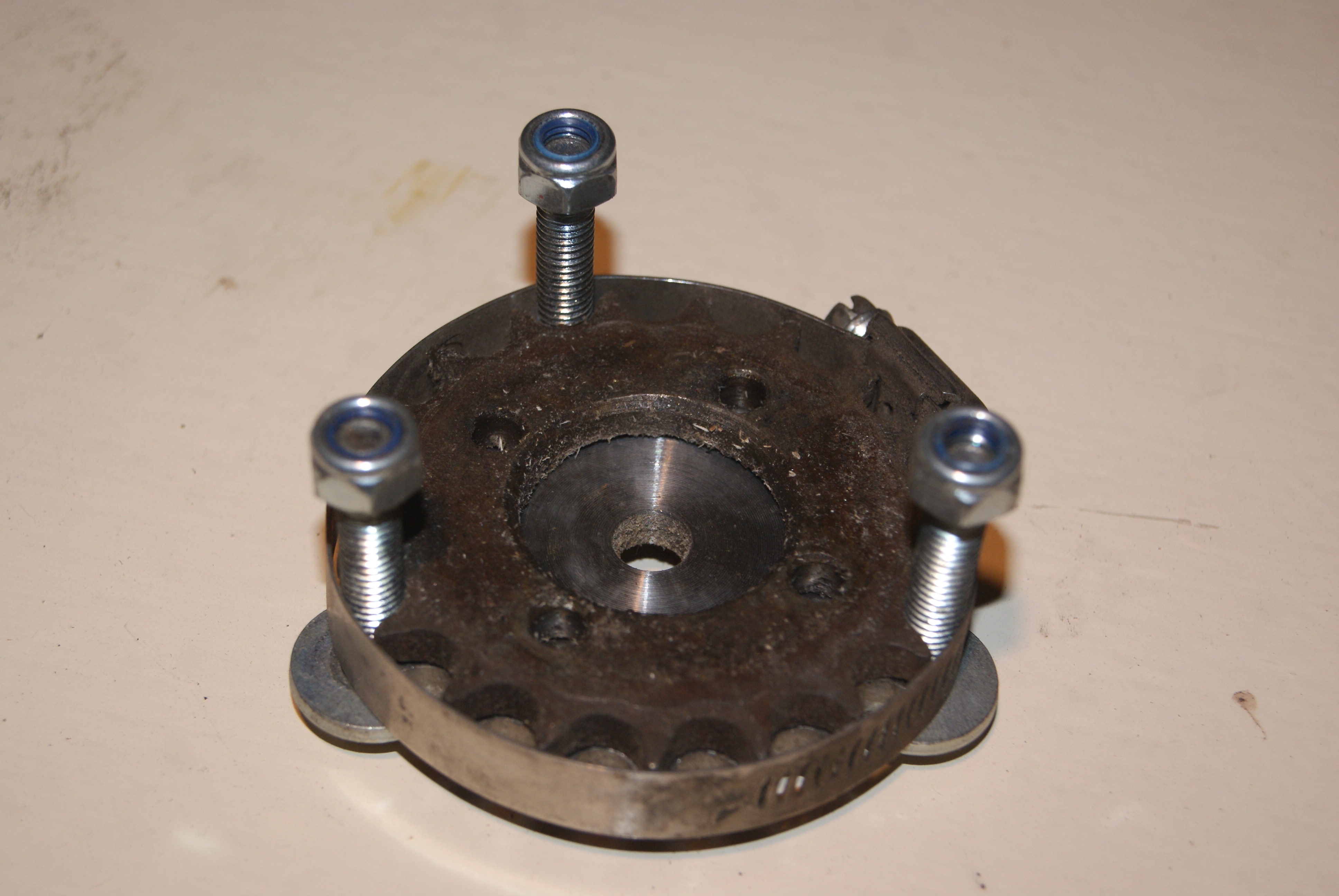
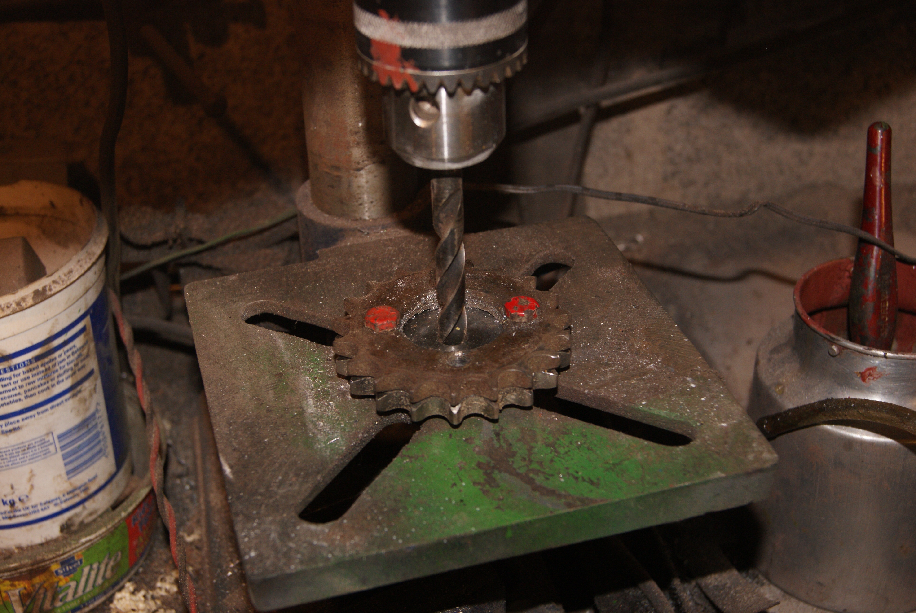
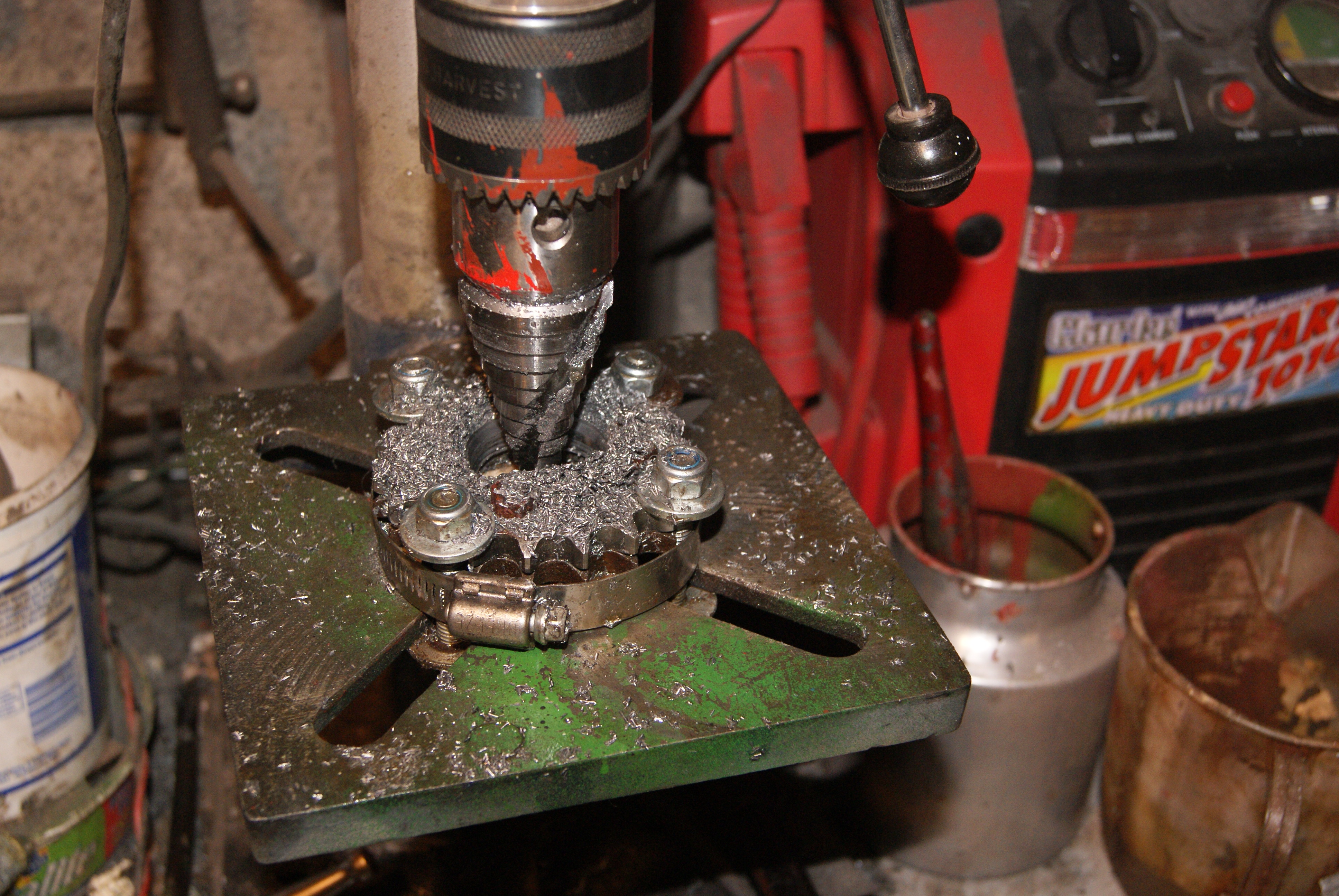
Now that the sprockets are held together by four 1/4″ bolts with nuts on the back I hit on the idea of using four 5/16″ bolts to hold it down to the table on the pillar drill; to stop them sliding off as I tightened them the old jubilee clip came in handy again. A 7/16″ drill through the centre hole fitted quite snugly, so I put that in the chuck and used it to centre the sprockets by tapping them this way and that until the drill entered the hole without binding (lots of patience here!).
It was then the work of a moment to swap the drill bit for the conical step drill and lower away, but very, very gently with loads of oil and backing off regularly to clear the swarf. I’ve had to call a halt on proceedings tonight because it started to chew the centre hole out of the table, so I’ve got to re-position it to give more clearance underneath. A job for tomorrow once the animals are fed!
Attachments:
April 24, 2020 at 6:41 am #33991charlieKeymasterMy eldest boy has been following Bad Obsession Motorsport and their Project Binkey on You Tube, actually a good series which I would recommend. They are avid users of the step drill in their many fabrications.
April 24, 2020 at 3:10 pm #33993trusty220KeymasterThe step drill has certainly done the business better than i could have hoped for. Whether a cheaper one would have worked just as well I don’t know, but this one claimed it would cut 5mm thick steel so I thought that it would be better. If you’re going to spend money on something like this, better to spend a little more and get a tool that’s going to last.
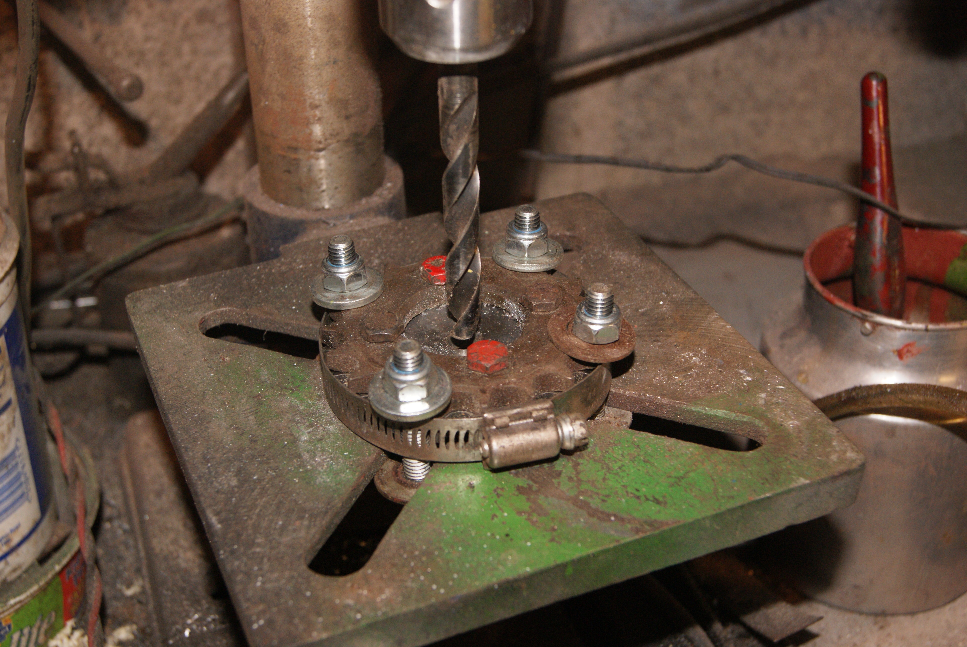
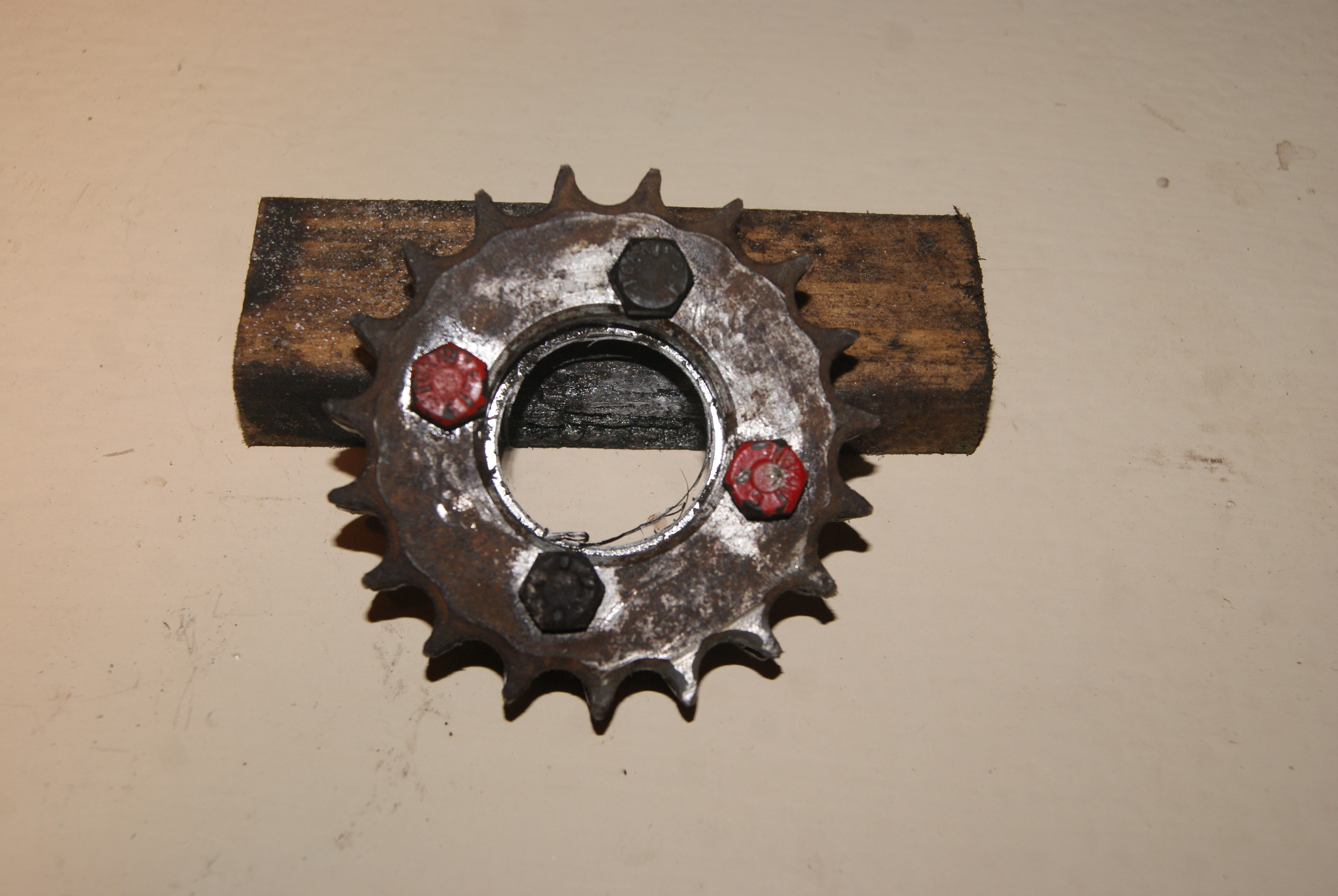
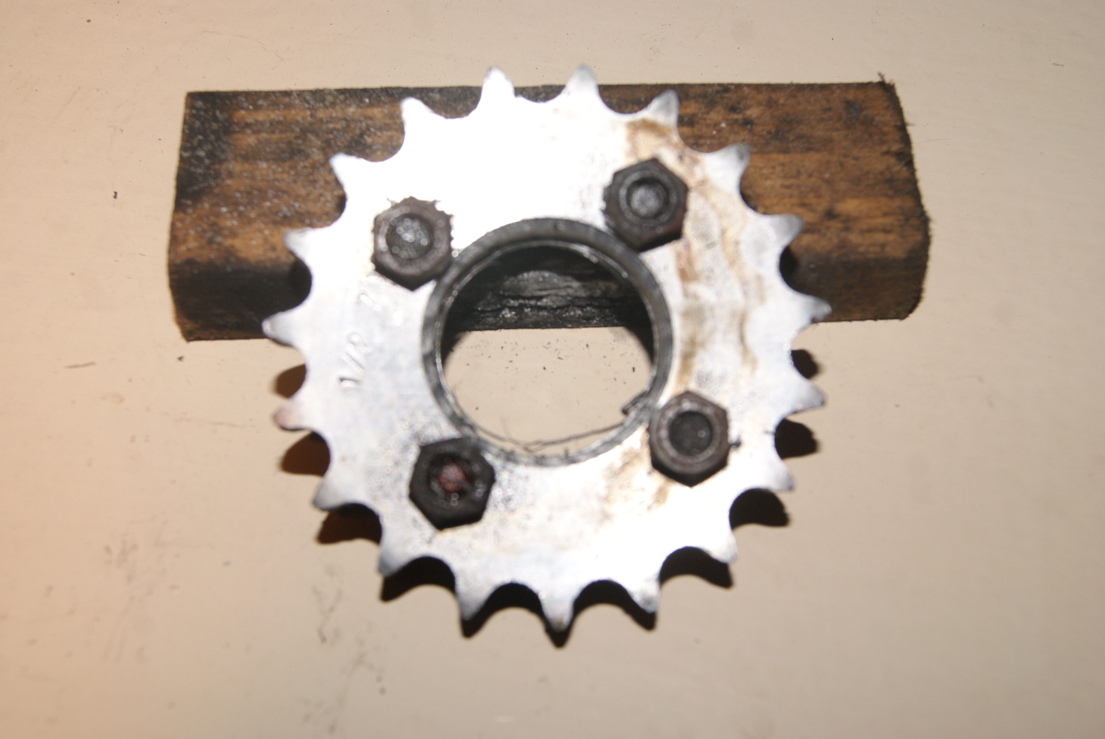
Anyway, I roped Mrs. Geoff into the job this morning to give me a hand to centre the workpiece again once I’d spaced it away from the table. Really I should have used metal blocks but all I had to hand was wood and so that had to do; the problem with using wood is that it compresses slightly and you have to be very careful how you tighten the retaining bolts otherwise the workpiece will tip slightly. The knack was to get her to lower the step drill into the hole and keep moving it up and down to feel if the sprocket was moving as I tightened the retaining screws. If it started to drag on one side or the other I then tightened the opposite side to bring it back into true again until I had it bolted down firmly. It was then a matter of drilling the rest out but stopping before the last step because it would make the hole too oversize. I found it handy to start the drill cutting the last step to leave a taper on the edge of the hole so that when I opened the hole out to the finished size with a half-round file I had a reference point on the outside; this helped in keeping the hole circular and concentric.
You can see the results in the pictures. I just hope they load in the correct order!
You Tube??? Does it look like I use a glue gun and bits of wood?
Attachments:
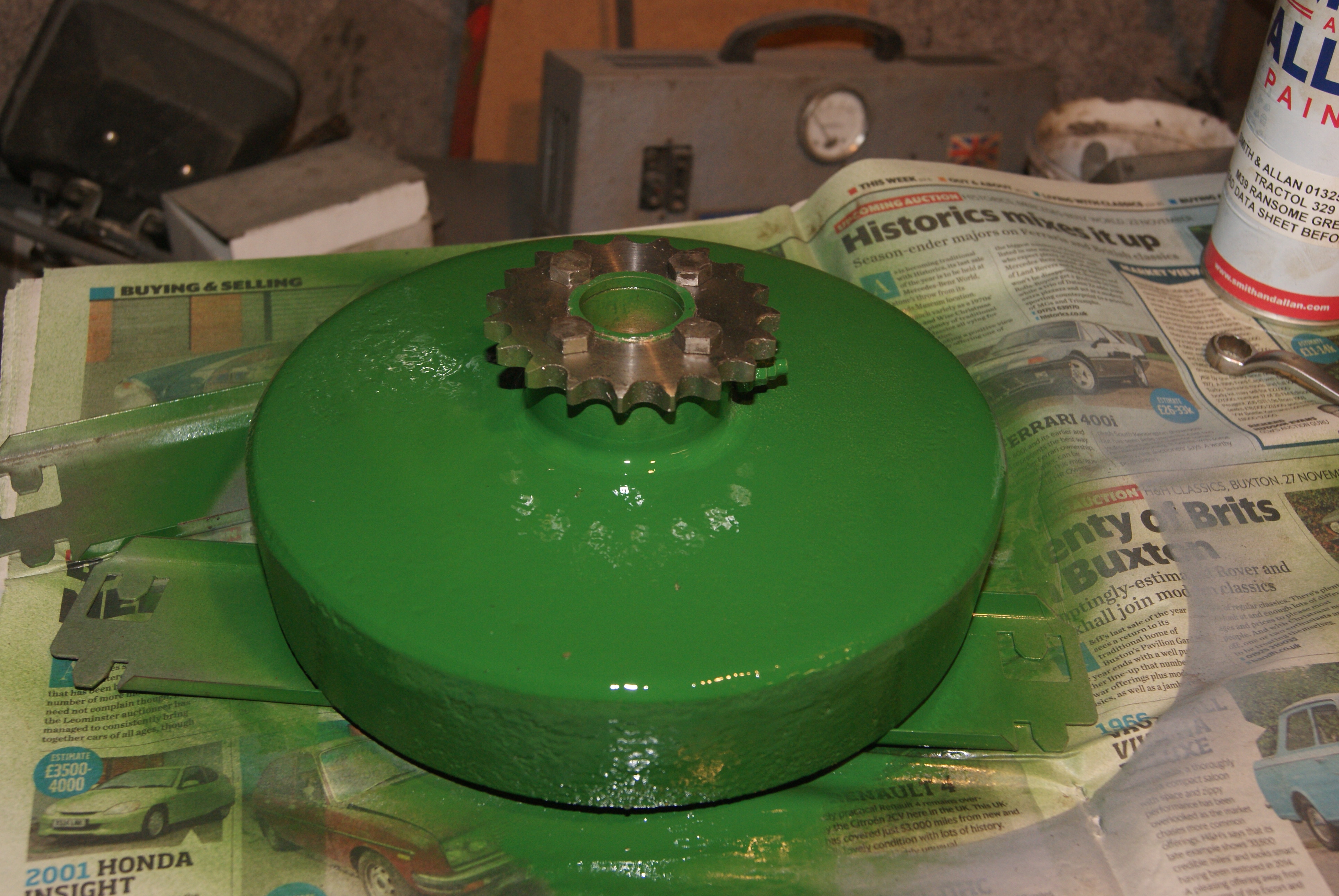
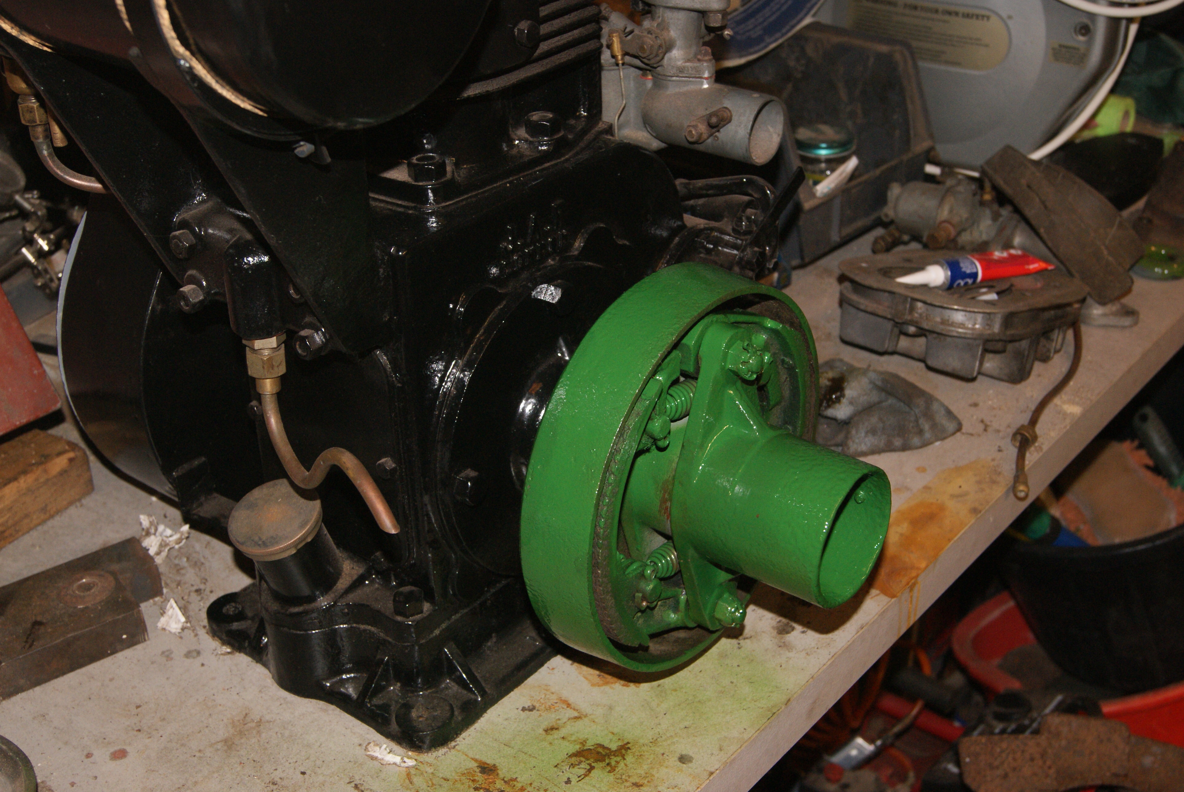
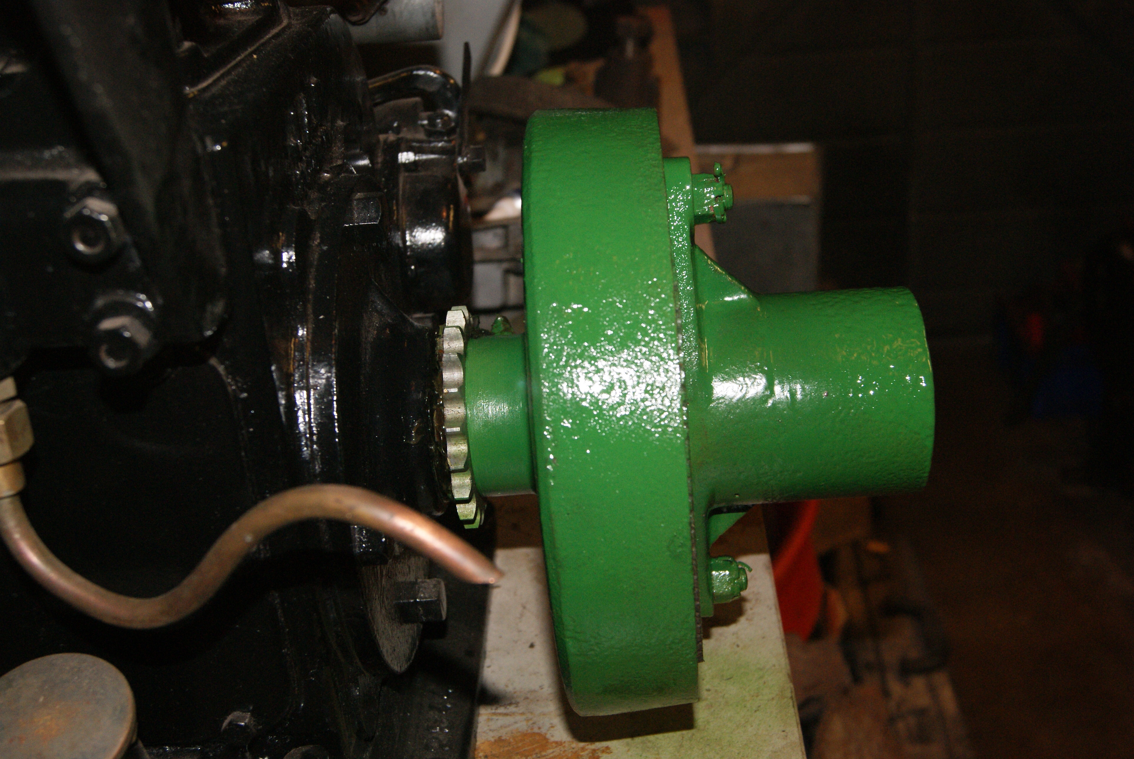
April 26, 2020 at 11:46 am #34013trusty220KeymasterJust so that you can see the final result, here are a few pictures of the clutch fitted up to the engine. A shame that It’s all hidden away once it’s finished but at least I know that it’s done properly.
This clutch is slightly different to the normal ones as the early JAP 5 has a taper on the end of the crankshaft, similar to the flywheel end, and so the clutch carrier is slightly different in that it has a reverse taper on it’s inside face. It is also located with a straight keyway but this should not have too much pressure exerted on it when working because the taper should be adequate to hold the clutch in place. The key itself was a strange one in that I had to file it to fit; the slot in the carrier was just wide enough at 3/16″ but the slot on the crank was slightly undersize in width and depth, but not enough to step down a size, so the only solution was to file it down to fit.
Attachments:
April 26, 2020 at 12:39 pm #34017andyfrost
ParticipantGeoff , I take it that you have been through the engine internals , that engine , and the later variant had a reputation for big end problems.
Andy.
April 26, 2020 at 6:04 pm #34018trusty220KeymasterYes, Andy, I went through it thoroughly the winter before last but I didn’t post it on the forum at the time, I don’t know why. It looks like it had done very little work so there was little wear that I could find. Most of the work on the tractor has been to rectify corrosion through being left to stand for long periods covered in soil.
Have a look at the dog clutches and you’ll see how little work the tractor has done. Maybe it was one that was bought so that the owner could have a petrol ration, then he put the petrol in his car- it has been known!
April 26, 2020 at 7:17 pm #34019 trustymasseymanParticipant
great photos & information Geoff. look forward to see photos of the draw bar restoration soon
-
AuthorPosts
- You must be logged in to reply to this topic.