Forum Replies Created
-
AuthorPosts
-
May 16, 2019 at 2:23 pm #31241
 vhgmcbuddyMember
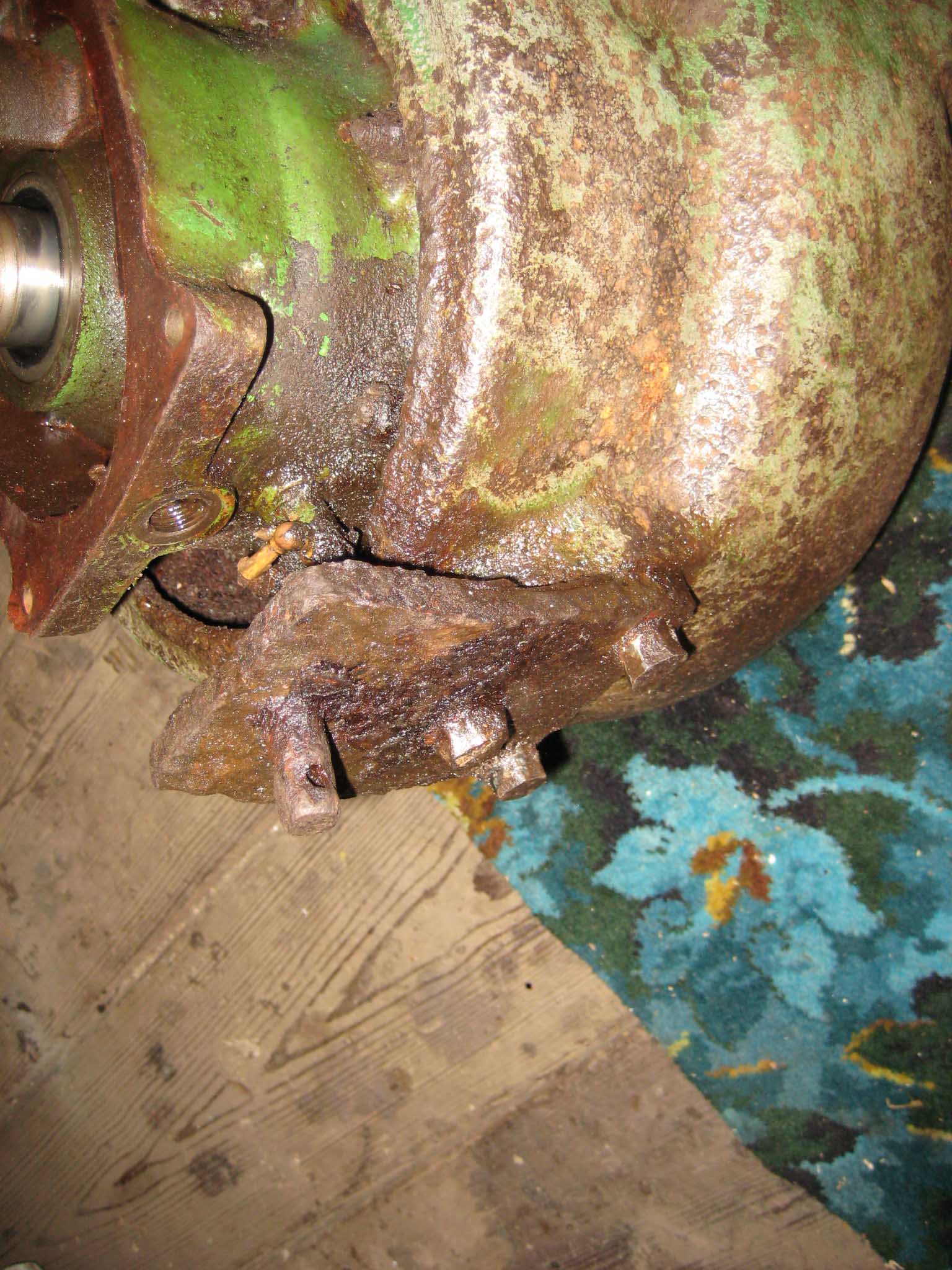
Here’s a pic now I have got it all out in the open air today
May 16, 2019 at 2:22 pm #31240vhgmcbuddyMemberI was hoping someone who had bought one recently could give me an idea of what price to list it at. Searched all going web sites on the scythe and model number but can’t find any others for sale at all. Just pictures of it. Seems finding one is a rarity and I will have to guess price it accordingly. Cheers
May 16, 2019 at 5:56 am #31234vhgmcbuddyMemberThanks Charlie.
What’s the best way to stop the crank from moving when you do this?
May 16, 2019 at 5:13 am #31231vhgmcbuddyMemberHello Chris,
Thanks I didn’t know it was called a taper lock coupling. I replaced the engine with a Loncin G200f-p as it was cheap so I could get the rotovator in action while I source a new exhaust valve for the Briggs. It is a Honda copy with a 3/4″ shaft which I checked and its correct. The engine fitted perfectly and has the same dimensions etc as the old Briggs. When I removed the flywheel I removed the allen grub screws but the flywheel was seized on and required some force to remove. I don’t think anything has been removed since new as when I changed gearbox oil I found the paint was still intact around the drain valve. The flywheel seemed tight when I replaced it but is tending to travel very slowly to the end of the shaft. I did also use the new key that came with the shaft which may be slightly different. It was longer but seemed to fit perfectly. Is there a special way of refitting using the two other holes in the coupling to tighten it before using the grub screws? As a last resort I was thinking of using a drop of thread lock on the shaft to see if it can hold it in place.
Thanks
AlasdairMay 15, 2019 at 5:21 pm #31228vhgmcbuddyMemberThank you for that, I appreciate it, I have some thread gauges, so when I am allowed to drive again and I have two arms again, I will go down the barn and check.
Regards Plonker
May 15, 2019 at 1:12 pm #31227vhgmcbuddyMemberWell, all part of thinking too much, I was very dubious as to how to do what you said, but… you guys are amazing!!
I did exactly what you said and I got a spark. I put the plug in and she fired up. Straight to it. No strangler open, no flooding of carb, but throttle wide. She turned over for maybe 4 or 5 seconds and then died. Subsequent tries she fired for less time each time and by the fourth or fifth try I just got one massive backfire with a foot long flame out the exhaust.
So now I need to adjust something I guess…..Suggestions will now be treated with reverence!
Thanks so much.May 14, 2019 at 6:19 pm #31223vhgmcbuddyMemberYes, there are 3 threaded holes in the underside of the engine cowling. Can’t remember what size the thread is, but they are metric.
May 14, 2019 at 2:40 pm #31221vhgmcbuddyMemberThanks Andy – 5/32″ BTDC – I understand to be 5/32″ of the stroke in a vertical sense, so with spark plug out and a stick in, I have one line marked on the stick where the piston reaches the top of stroke TDC – and a line marked 5/32″ above that where the spark should happen.
But what I am finding is that the points seem to be open for most of the flywheel revolution and only close briefly. I don’t understand how the flywheel shaft that moves the points can be circular, except for a small flattened area. The flattened area is where the points get a chance to close, but otherwise are held open. And if or when the governor kicks in, it completes the circular part where the flat part is, keeping the points open all the way round.
And yet the spark is only formed when the points open briefly.
Well, that’s how it works on the landrover. Is this system fundamentally different?
In addition to which, when the points are just opening the points are behind one of the three ‘spokes’ of the flywheel and so I am unable to adjust the gap.
I am mighty confused.
RobinMay 14, 2019 at 11:36 am #31220vhgmcbuddyMemberThanks for taking the trouble to photo it for me, very helpful, it is different, but still seems to be simple to fabricate from what looks like 3/8″ plate,I assume there are threaded hole alrady under the engine for this plate to bolt on? I cant get to mine at the moment because I have one arm in a sling and cant drive! Regards Plonker
May 13, 2019 at 7:18 pm #31218vhgmcbuddyMemberSo, pre-2000 models seem to be RAL6025 Fern Green apparantly, not convinced
May 13, 2019 at 7:11 pm #31217vhgmcbuddyMemberI see, its usually the way that something so simple could be so complicated
I shall continue investigations and post any updatesMay 13, 2019 at 6:31 pm #31214vhgmcbuddyMemberHere’s a photo of the plate attached to the underside of the engine cowling on my 56a. Definitely different to the one on Peter’s machine. Hope this helps.
Sean
Attachments:
May 13, 2019 at 6:06 pm #31213vhgmcbuddyMemberNo i havent to be honest. Just assumed they would be too old for them to be bothered with.
May 13, 2019 at 3:20 pm #31211vhgmcbuddyMemberThanks Alan. That spacer looks brass, or is that a trick of the light? Strange that the right hand handle is closer to the wheel than the left – I would expect the whole thing to be symmetrical.
May 13, 2019 at 2:29 pm #31208vhgmcbuddyMemberAgain, Many thanks to you both for taking the trouble to crawl about giving me so much useful information, If my plate is missing, It should be simple to fabricate one out of 3/8″ plate, at least I know where to look! Thanks again Plonker
-
AuthorPosts