
Forum Replies Created
-
AuthorPosts
-
October 11, 2015 at 10:54 am #14820vhgmcbuddyKeymaster
The big end journal mikes at 1.865/1.864″.
Is this the standard size or a regrind ?
As for the exhaust port—- I may have to bore it out and sleeve it back to the original size.
It’s quite badly eroded.
SilverfoxOctober 10, 2015 at 10:03 pm #14818vhgmcbuddyKeymasterThe engine is cleaned and stripped.
Not in bad condition.
The big end bearing journal is in good condition, but I will replace the shells and the main bearing.
The valves require re-seating but are usable.
The timing chain is a bit stretched and I will replace it.
The main problem is the exhaust port.
How is the exhaust pipe fitted to the cylinder
All I have is a rusted hole in the cylinder and 2 tapped holes.
Is something missing?
Does anyone have a picture of this area?
SILVERFOXOctober 10, 2015 at 9:59 pm #14817vhgmcbuddyKeymasterThe big chunk of channel iron on the left of the engine bay is embossed ” Dorman Long Middlesborough ” and is also stamped on the edge 137
https://www.dormanlongtechnology.com/en/Dorman%20Long%20historical%20information.htm
October 10, 2015 at 8:48 am #14810vhgmcbuddyKeymasterThe big chunk of channel iron on the left of the engine bay is embossed ” Dorman Long Middlesborough ” and is also stamped on the edge 137
Attachments:
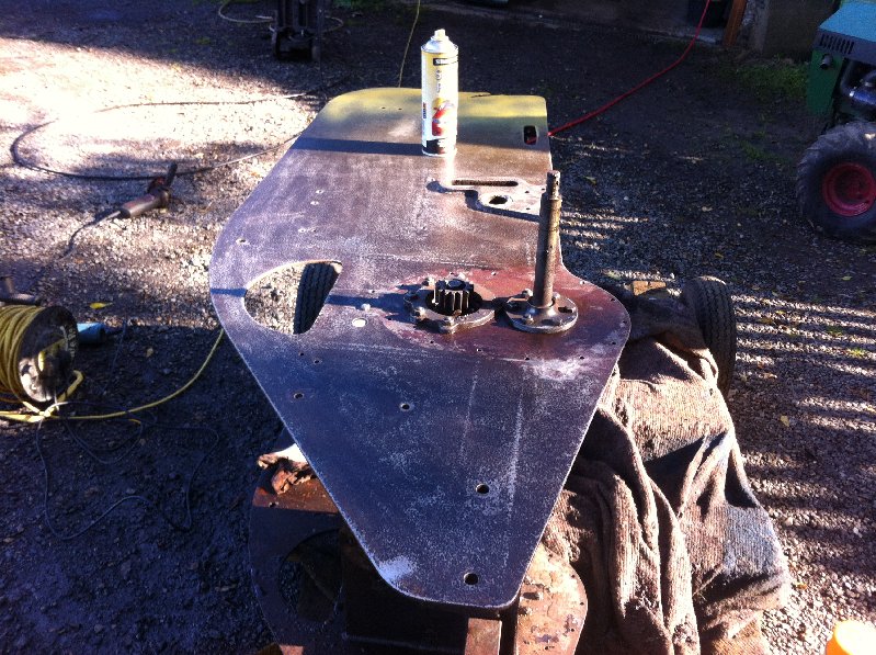
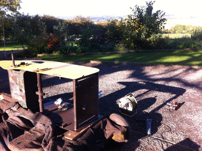
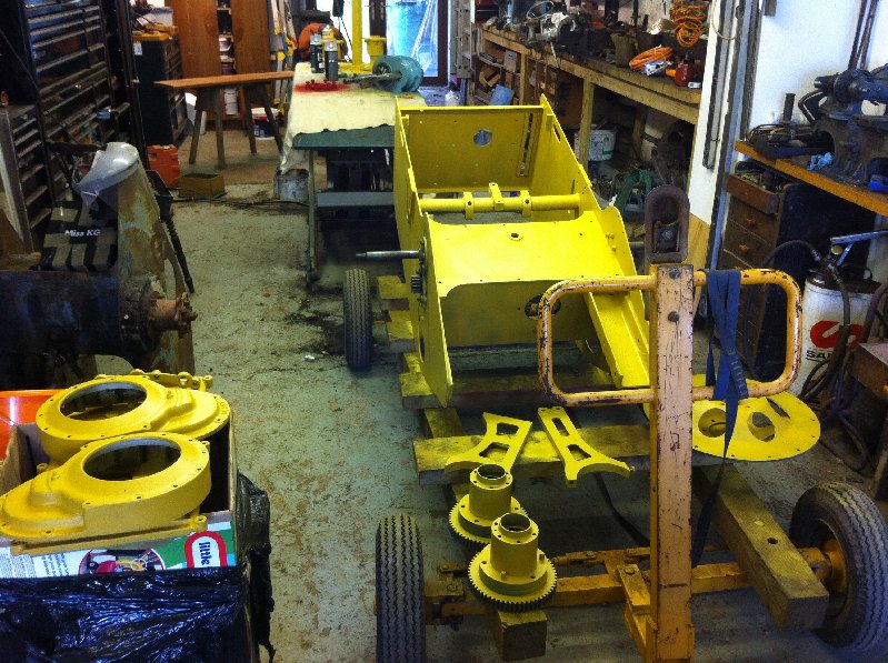
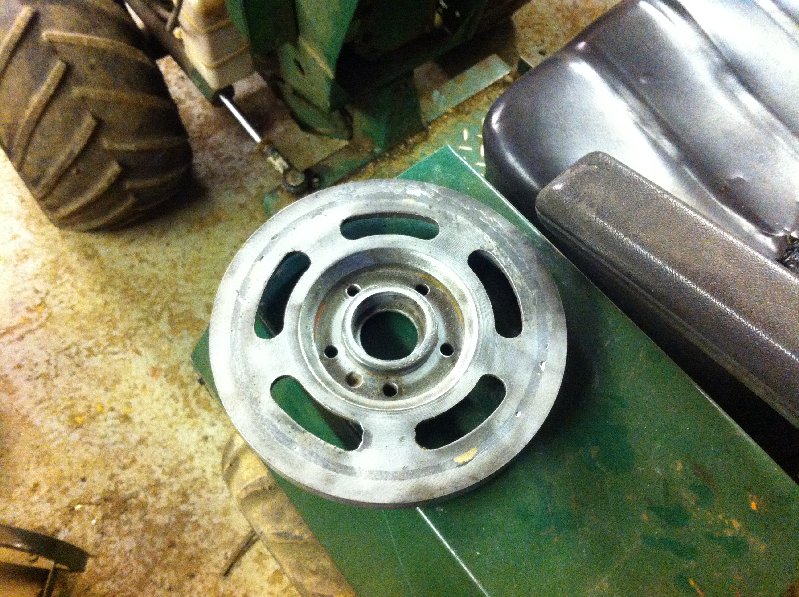
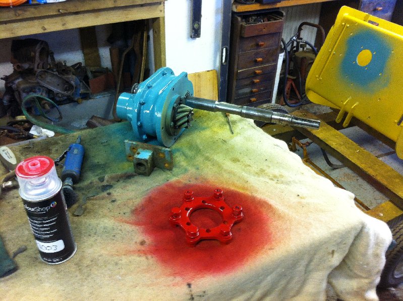
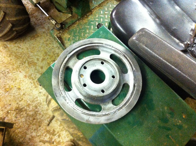
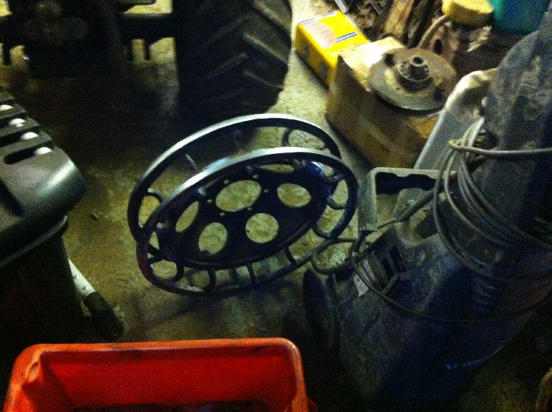
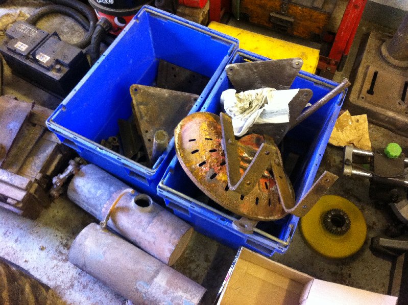
October 10, 2015 at 8:40 am #14803vhgmcbuddyKeymasterFinally managed to finish the idler wheels and the load rollers. The idlers were rebuilt to size using 1/2″ square bar rolled and brazed to the rims, the rollers were restored to size using 1/2″ slices of 8″ dia cast bar bored out to an interference fit located on rawl pins and then brazed, should last another 80 years. In the meantime I have sanded off the body acid treated it with phosphoric and then given it a light coat of primer putty to stop any re rust, I will now apply a light skim of filler to fill the rust pits. All the bolt on bits have been through my electrolysis tank ,been shot blasted, acid treated and primed, I am working my way through a bog box of parts and thankfully can now see the bottom of the box.
Some parts of the tractor still had original paint, which looked different to the Orwell blue and the red commonly used, I tested the colours on a spectograph and came up with a turquoise ( 102 ) and Ruby red (3003) I ordered some test aerosols and tried it out with very pleasing results. As I do not think that these machines were ever shiny gloss finish I have opted for a satin finishAttachments:
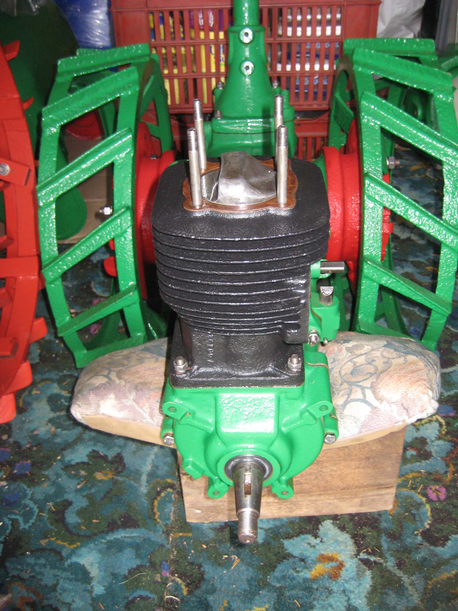
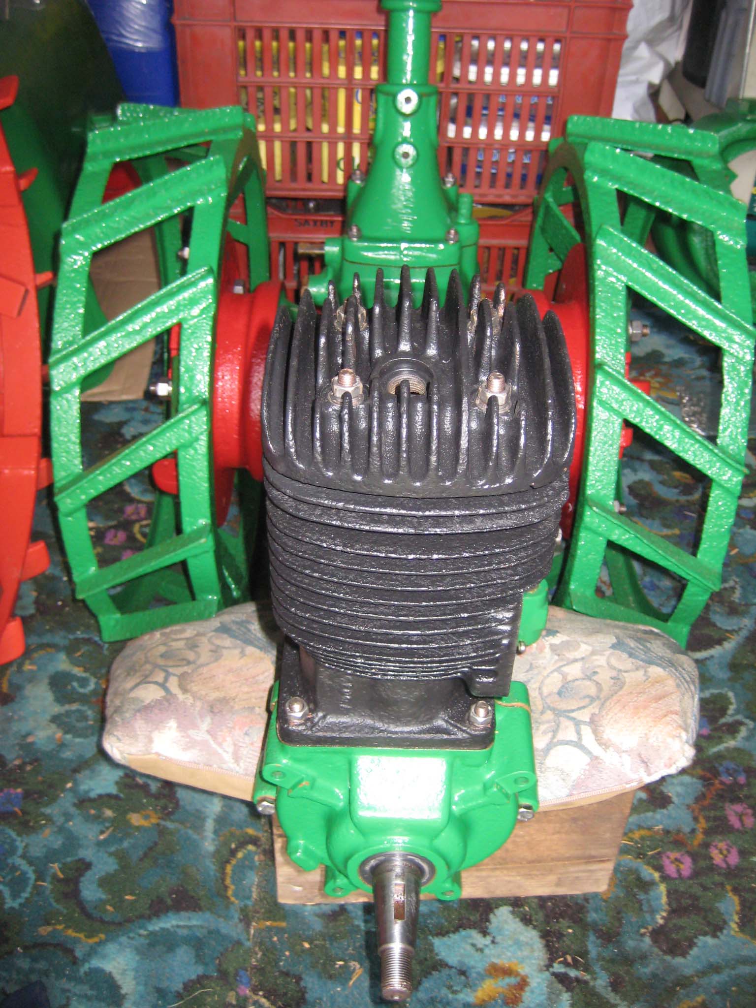
October 7, 2015 at 5:08 pm #14787vhgmcbuddyKeymasterAfter refitting the piston, the cylinder barrel, cylinder head studs and head gasket were installed (Simar 0071). Note the orientation of the piston. The cylinder head needs to be aligned so the spark plug hole is towards the front (Simar 0072).
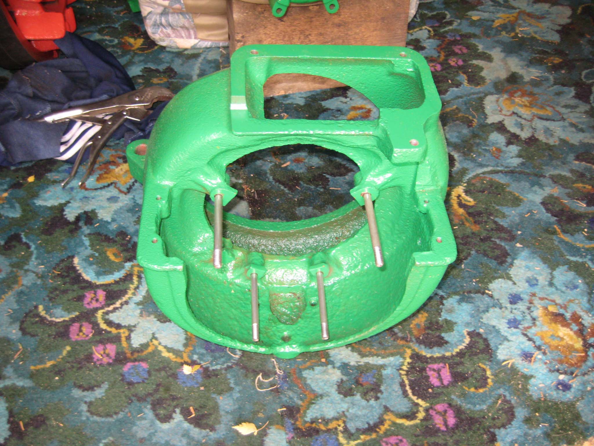
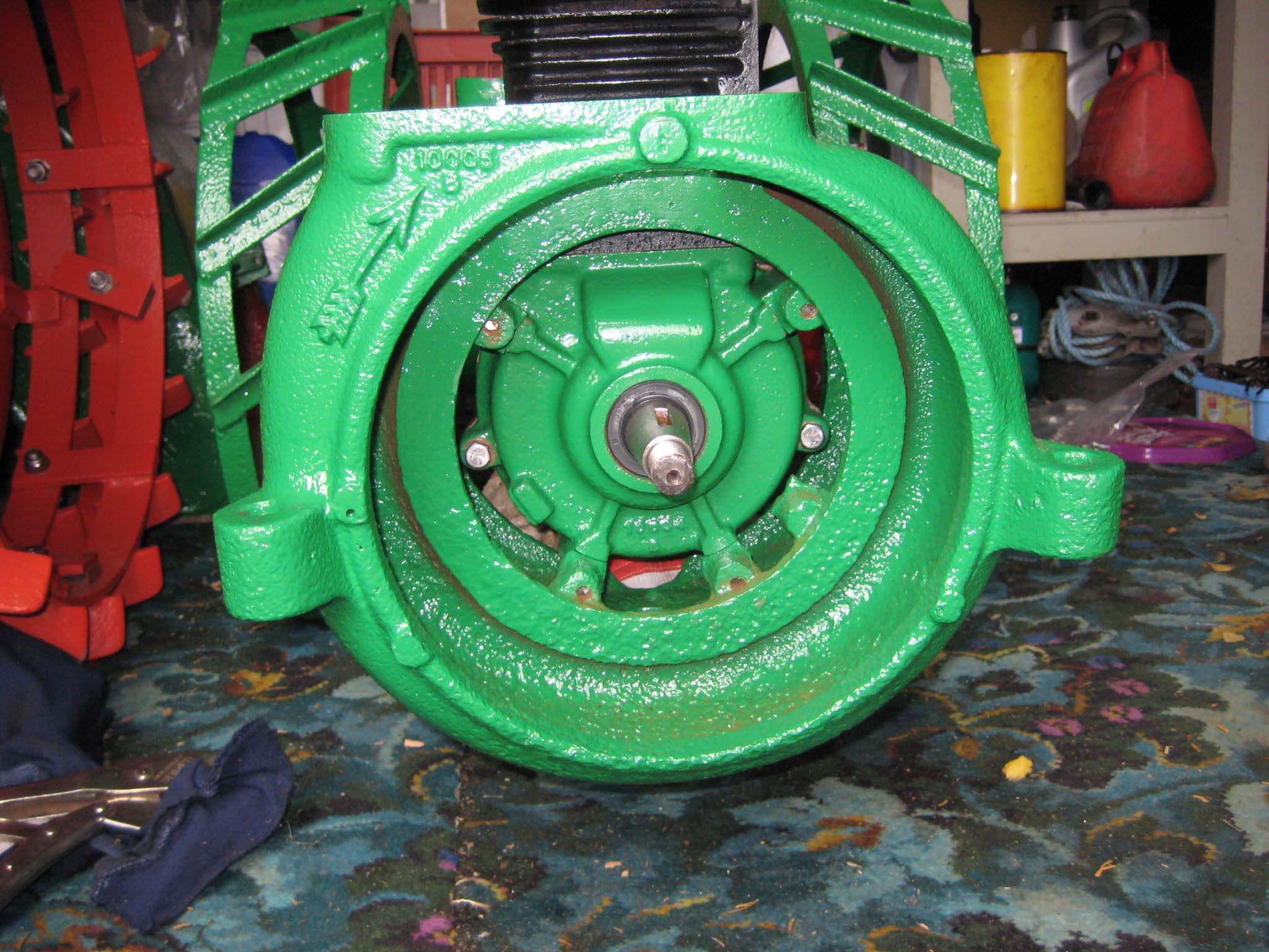
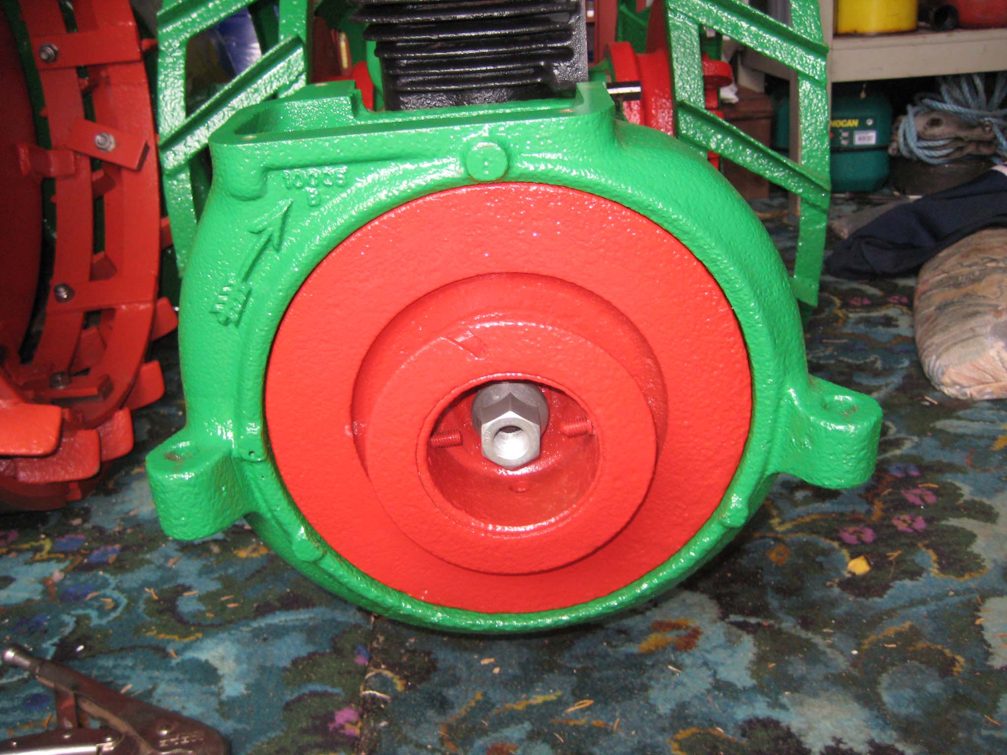
The cooling fan casing was prepared by installing the four M8 mounting studs (Simar 0073) and then fitted to the crankcase (Simar 0074). The cooling fan fits on the tapered crankshaft via a half moon key. A M18 x 1.5 nut holds the fan in place. The original nut was too corroded for reuse, so a replacement was obtained in the form of a wheel nut from a piece of agricultural machinery (Simar 0075). This also had the advantage of being a flanged nut, therefore I did not require the large washer which was used with the original nut. Note that in the photo the nut has yet to be tightened. The cylinder was filled with a cloth rag to lock the piston in place to allow the nut to be tightened.Attachments:
October 6, 2015 at 8:29 pm #14784vhgmcbuddyKeymasterMore blue bits just got main frame to sort next
Attachments:
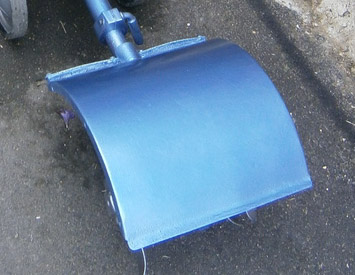
October 5, 2015 at 6:32 pm #14781vhgmcbuddyKeymasterRight people im needing some help im currently looking for one of these its a a metal cover for the rotovator head. As in the picture ? If anybody has one in reasnoable condition please contact me as ill happily buy it off you
Attachments:
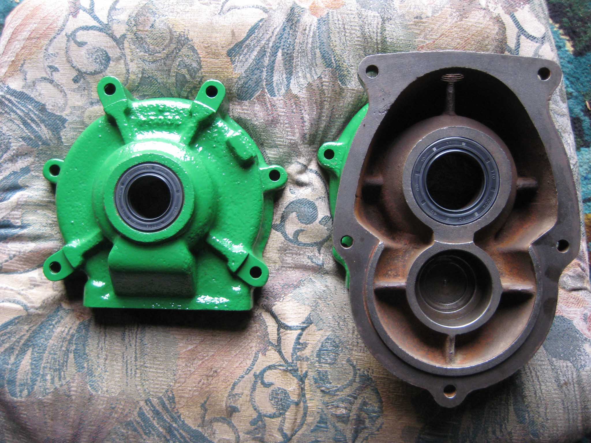
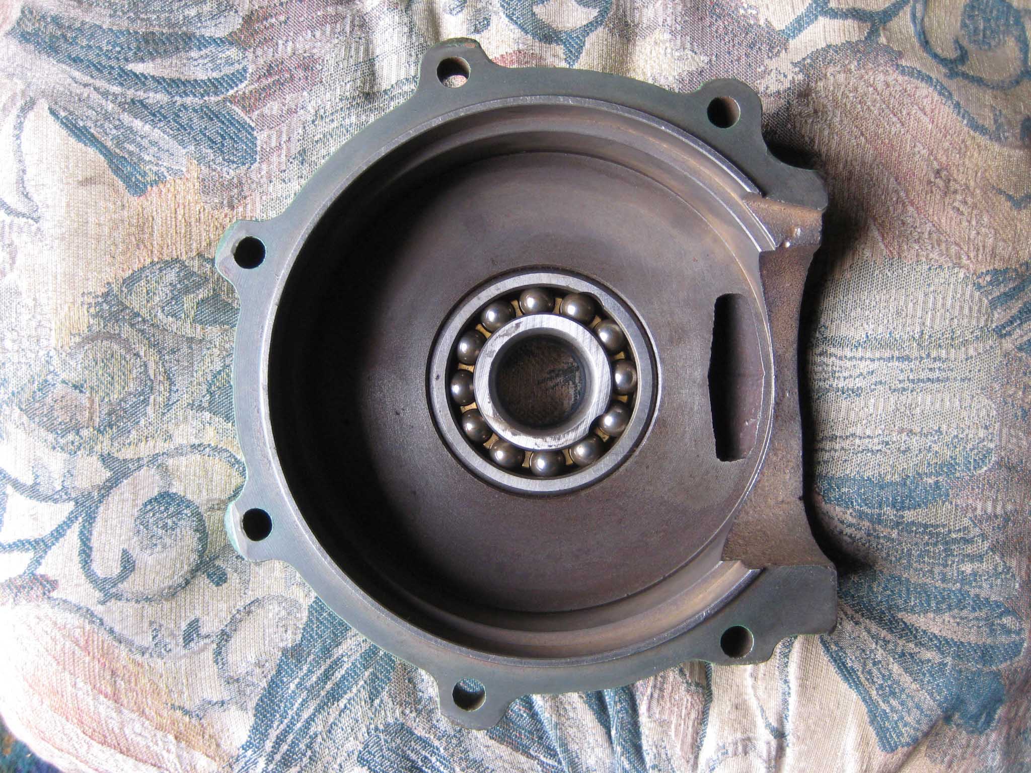
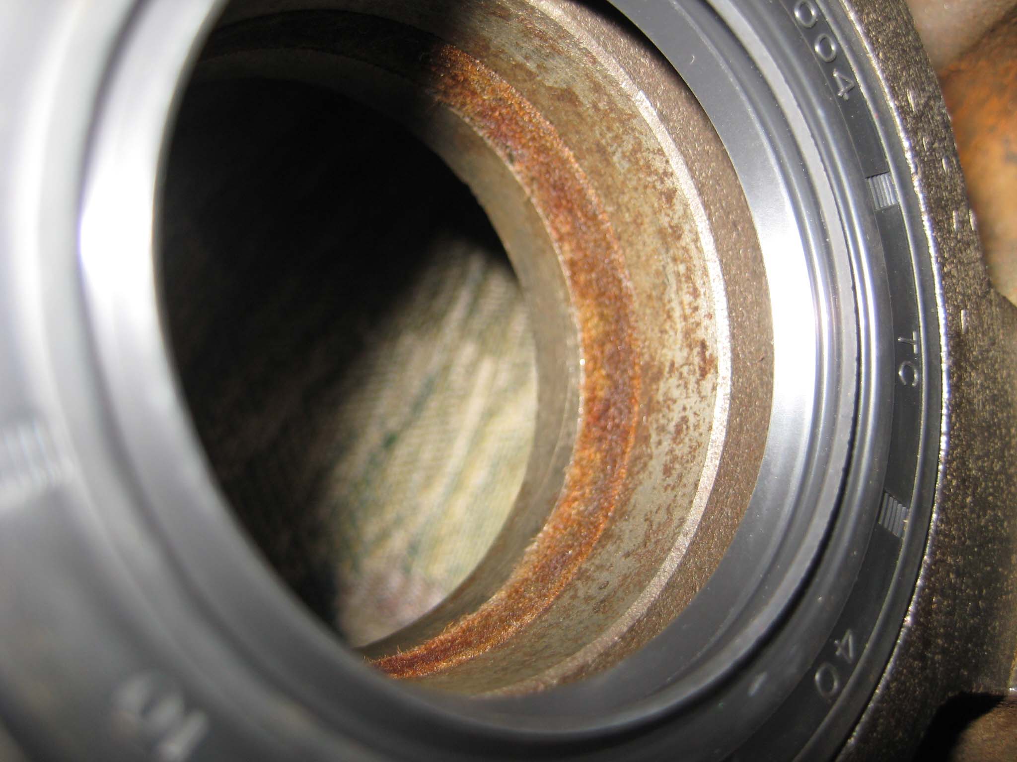
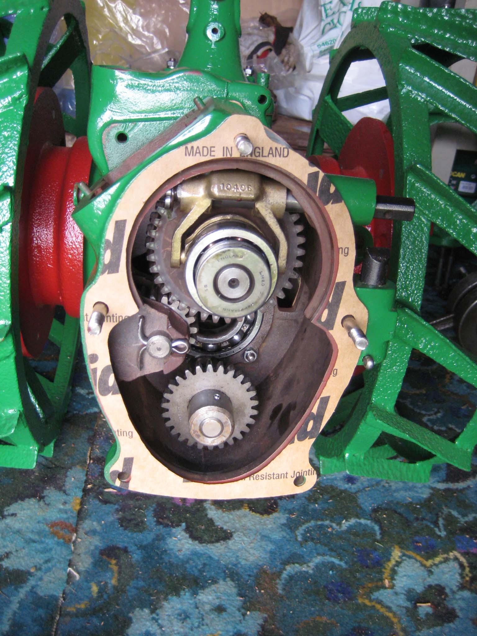
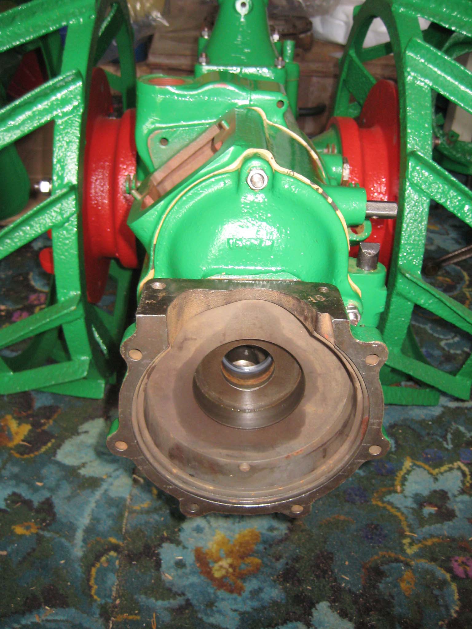
October 5, 2015 at 6:19 pm #14770vhgmcbuddyKeymasterThe crankcases were prepared for assembly by fitting new oil seals, 60mm O/D, 40mm I/D, 10mm wide for the rear crankcase and 47mm O/D, 30mm I/D, 10mm wide for the front crankcase (Simar 0061). The front crankcase also contains a double roller bearing (Simar 0062). As this bearing sits in a blind hole, it cannot be pressed out, so removal would require a special blind bearing removal tool which normally results in the bearing being damaged. As the bearing was in good order, I did not attempt to remove it. The rear crankcase contains a machined groove into which is inserted a felt washer (Simar 0063). A new paper gasket was fitted to the reverse gearbox casing (Simar 0064) and the rear crankcase secured into position on the three long M8 studs (Simar 0065). At the same time, the M8 x 50 bolts were fitted which secure the reverse gearbox to the main gearbox and rear crankcase to the reverse gearbox (Simar 0066). All were gradually tightened, in the same fashion as a cylinder head, to ensure an even pressure.
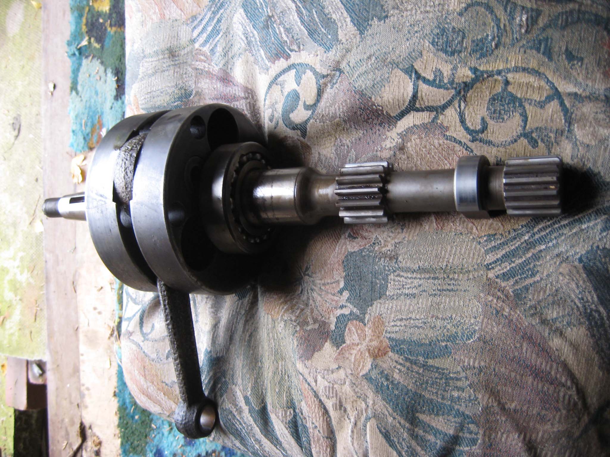
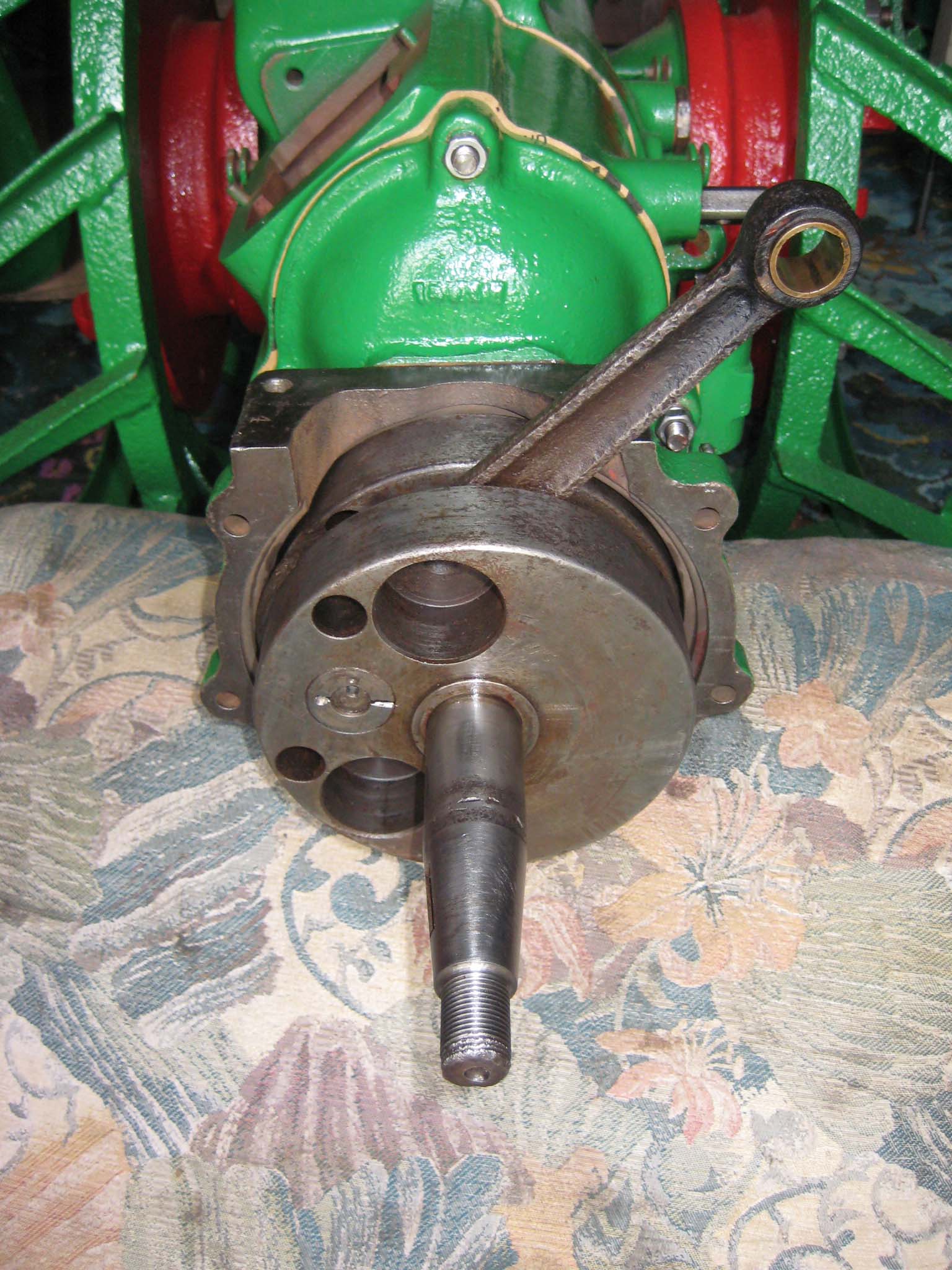
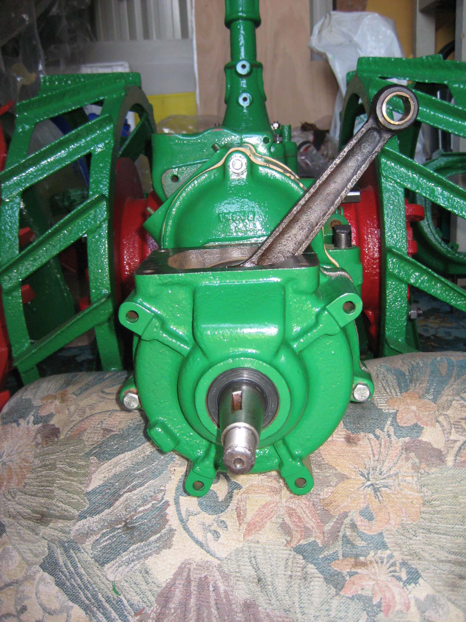
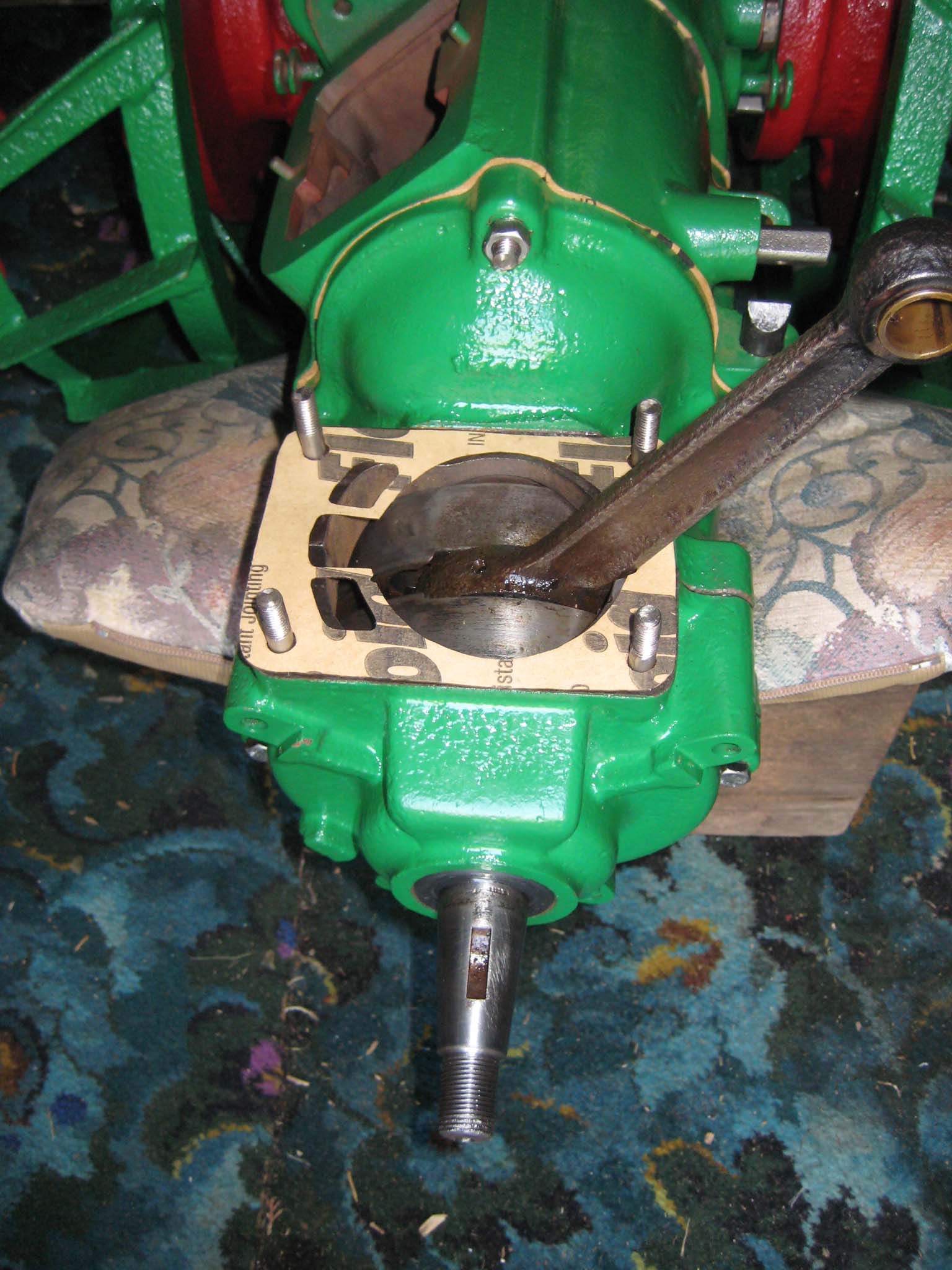
I did not take the engine crankshaft apart (Simar 0067), as reassembling would require a jig to ensure both front and rear sections of the crankshaft are perfectly concentric. The whole lot was slid into place, taking care not to damage the oil seal in the rear crankcase (Simar 0068). A distance washer is fitted up against the front flywheel before the front crankcase is installed (Simar 0069). The front crankcase is fixed to the rear crankcase by two M8 x 55 bolts. The other four vacant fixing holes visible in the photo also carry the front cooling fan casing. Four short M8 studs and paper gasket were then fitted ready for the cylinder barrel (Simar 0070).Attachments:
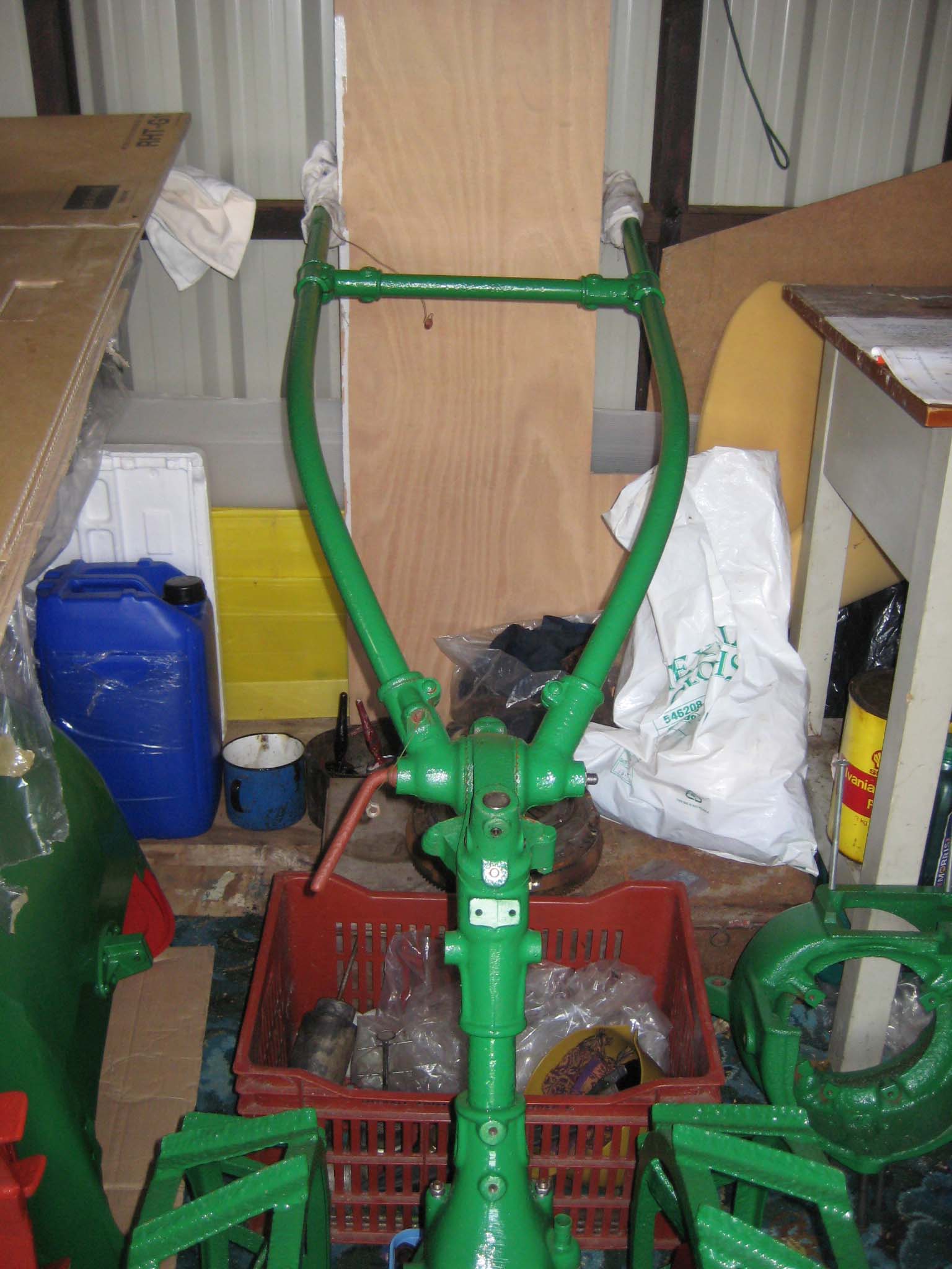
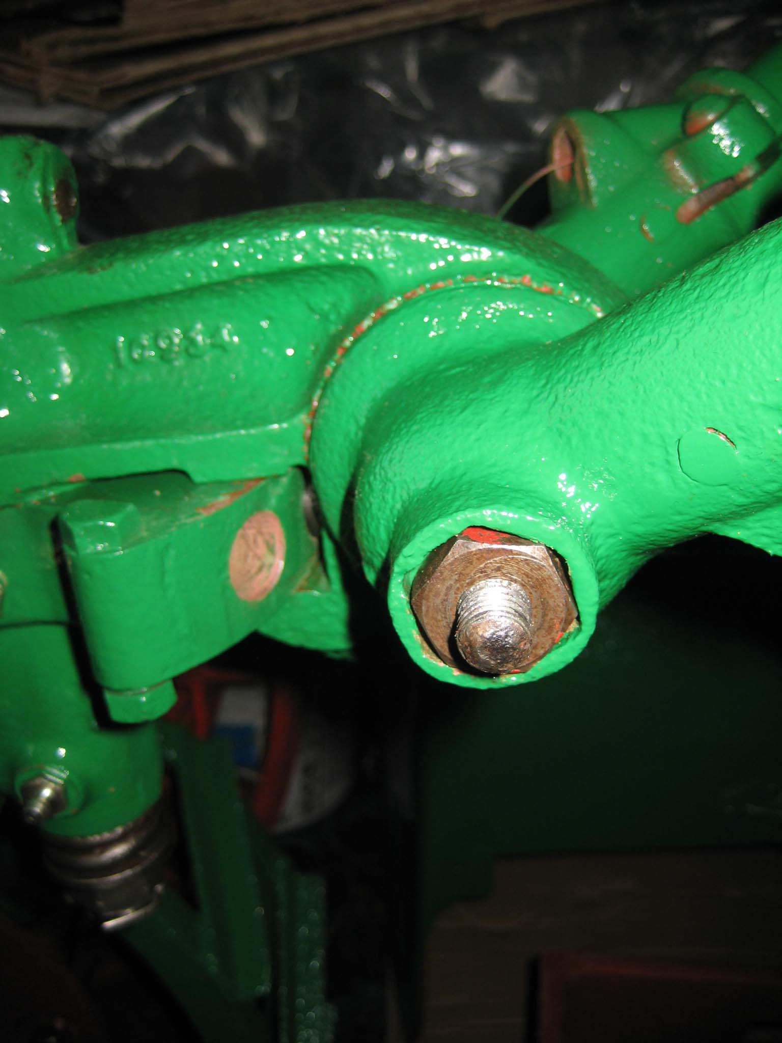
October 5, 2015 at 6:14 pm #14762vhgmcbuddyKeymasterThe handlebars are attached to the steering column via a locking handle and M12 nut (Simar 0054 & 55). Note that the M12 nut is larger across the flats than a normal plain M12 nut, as it fits into a hexagon recess at the handlebar pivot.
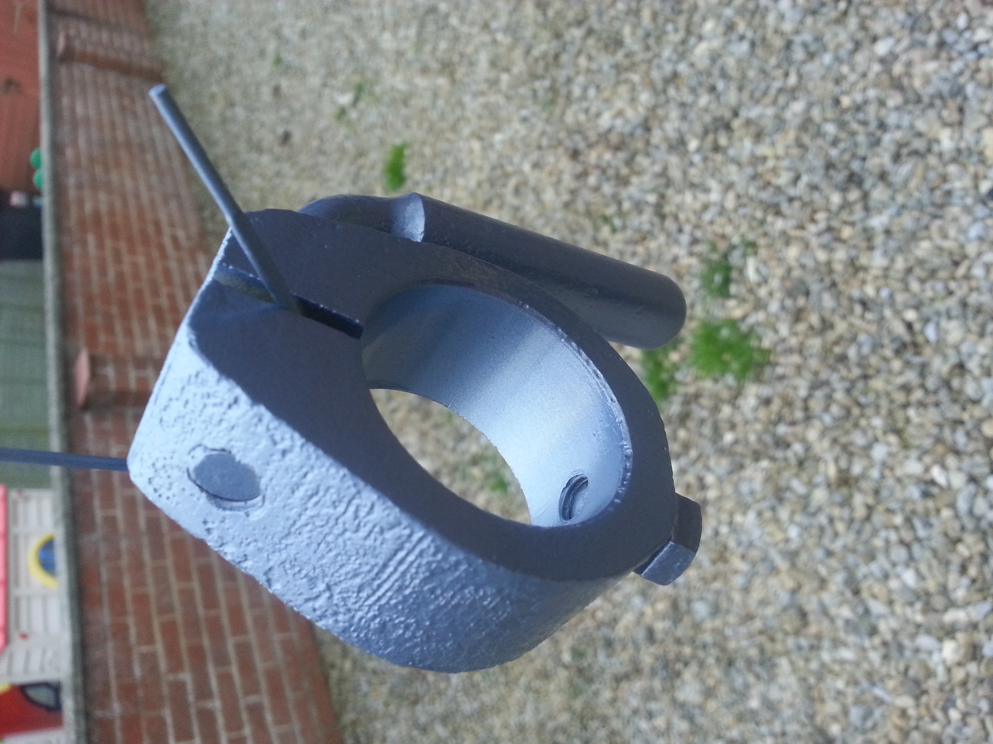
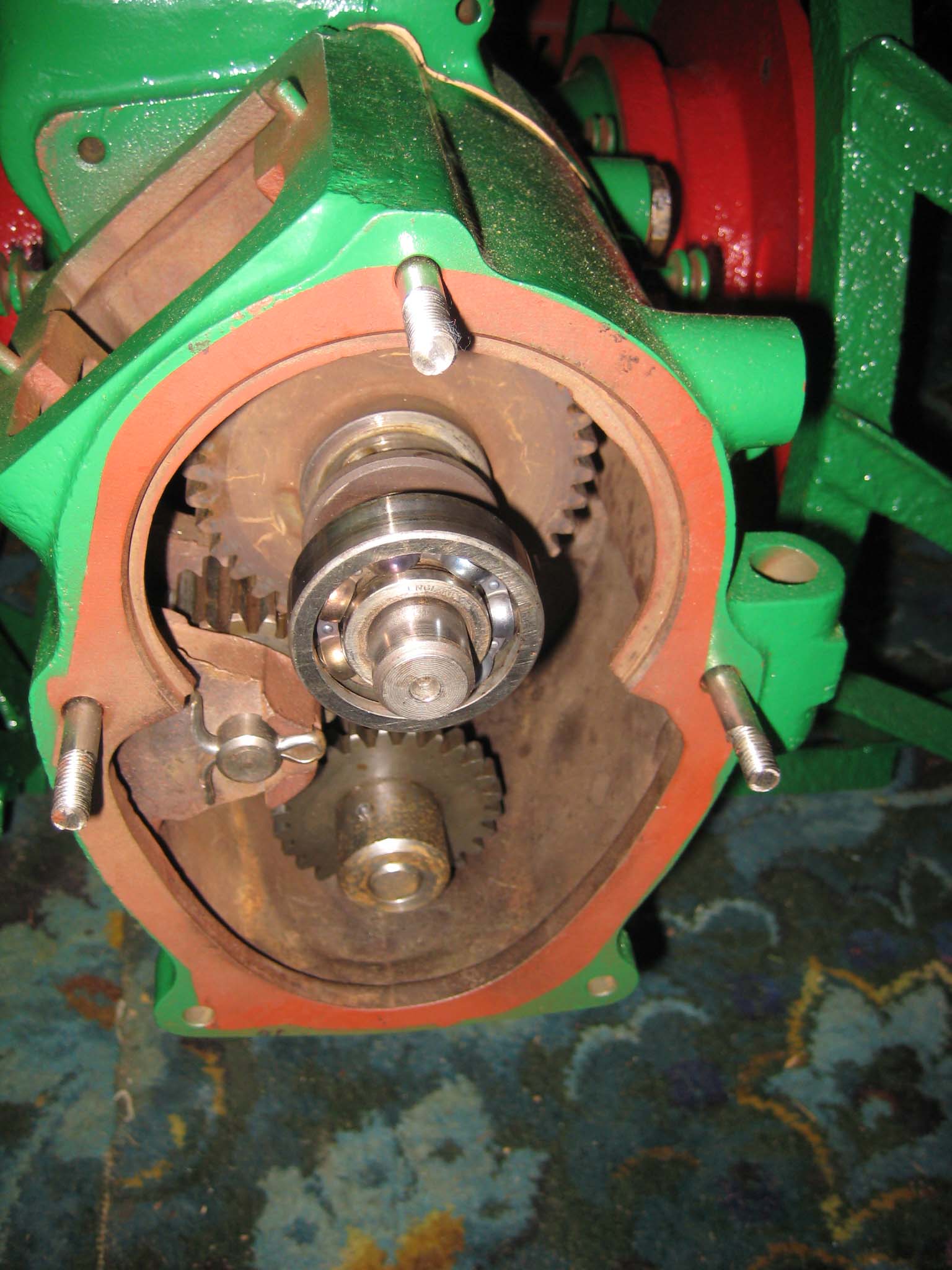
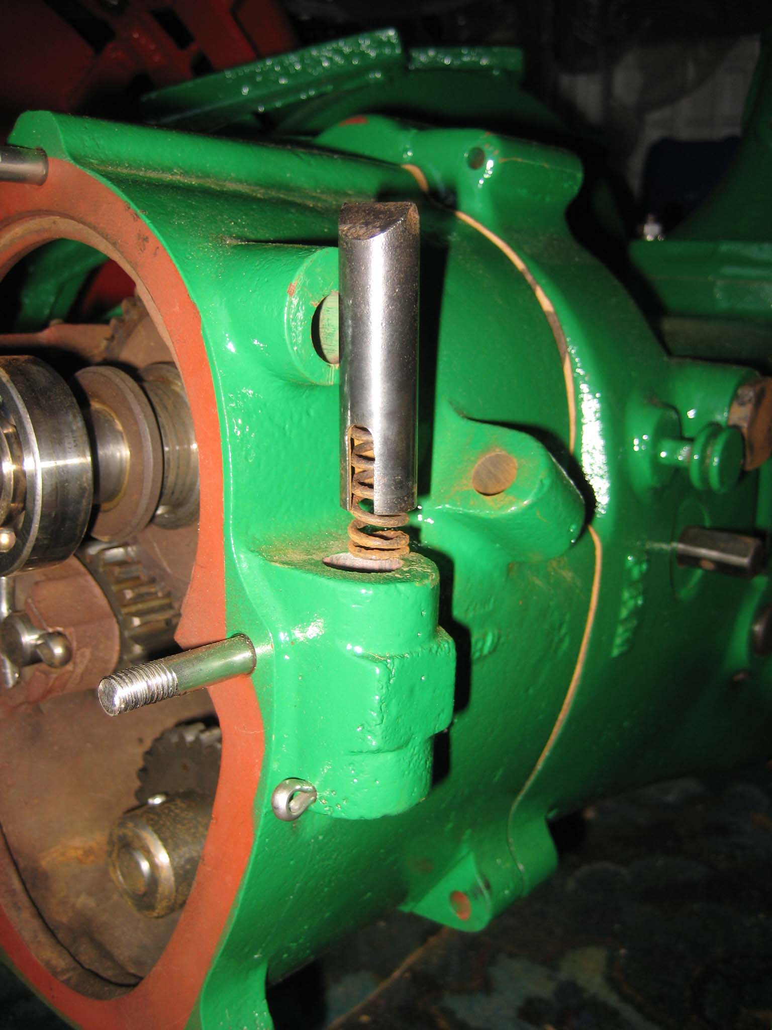
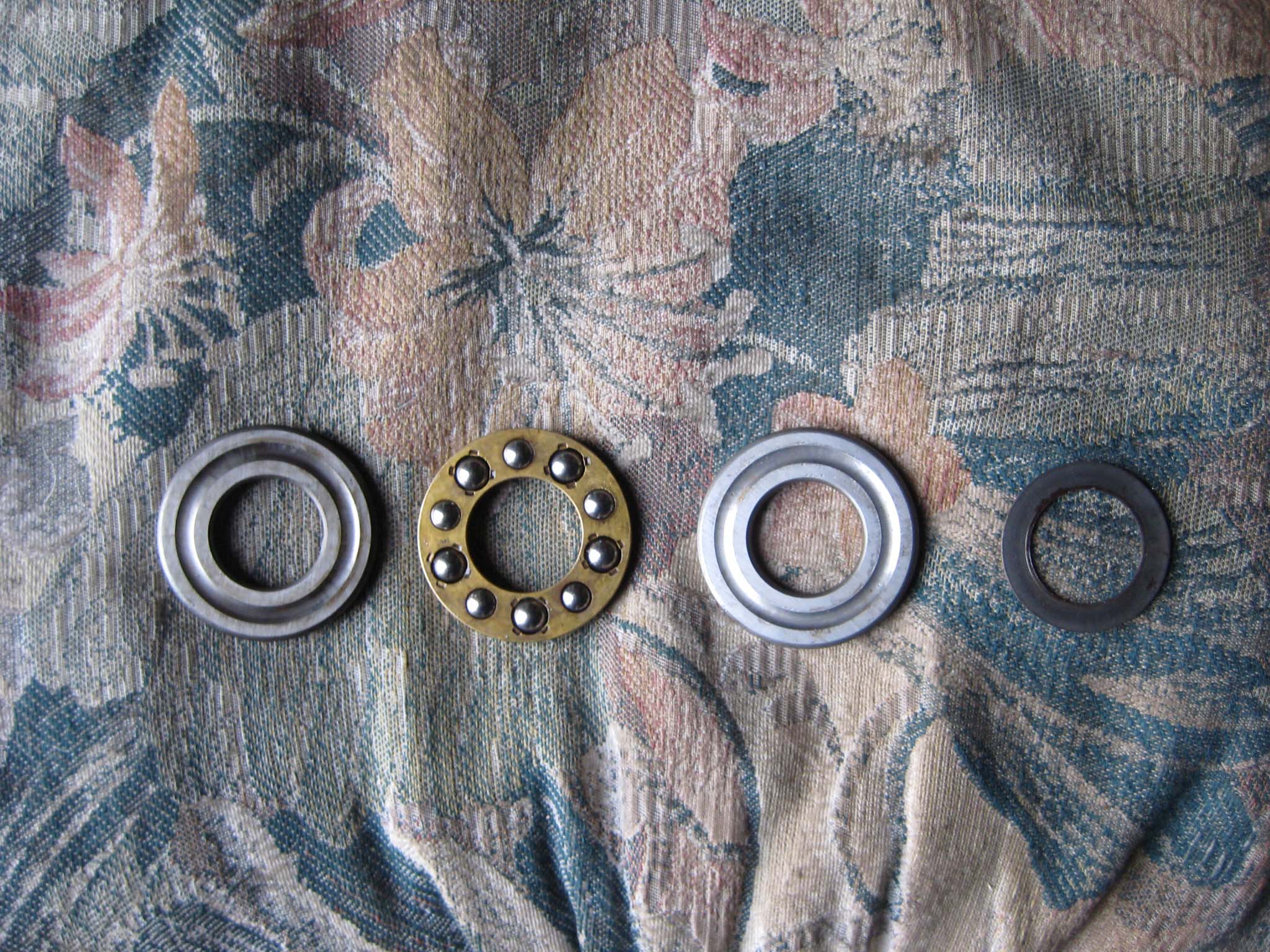
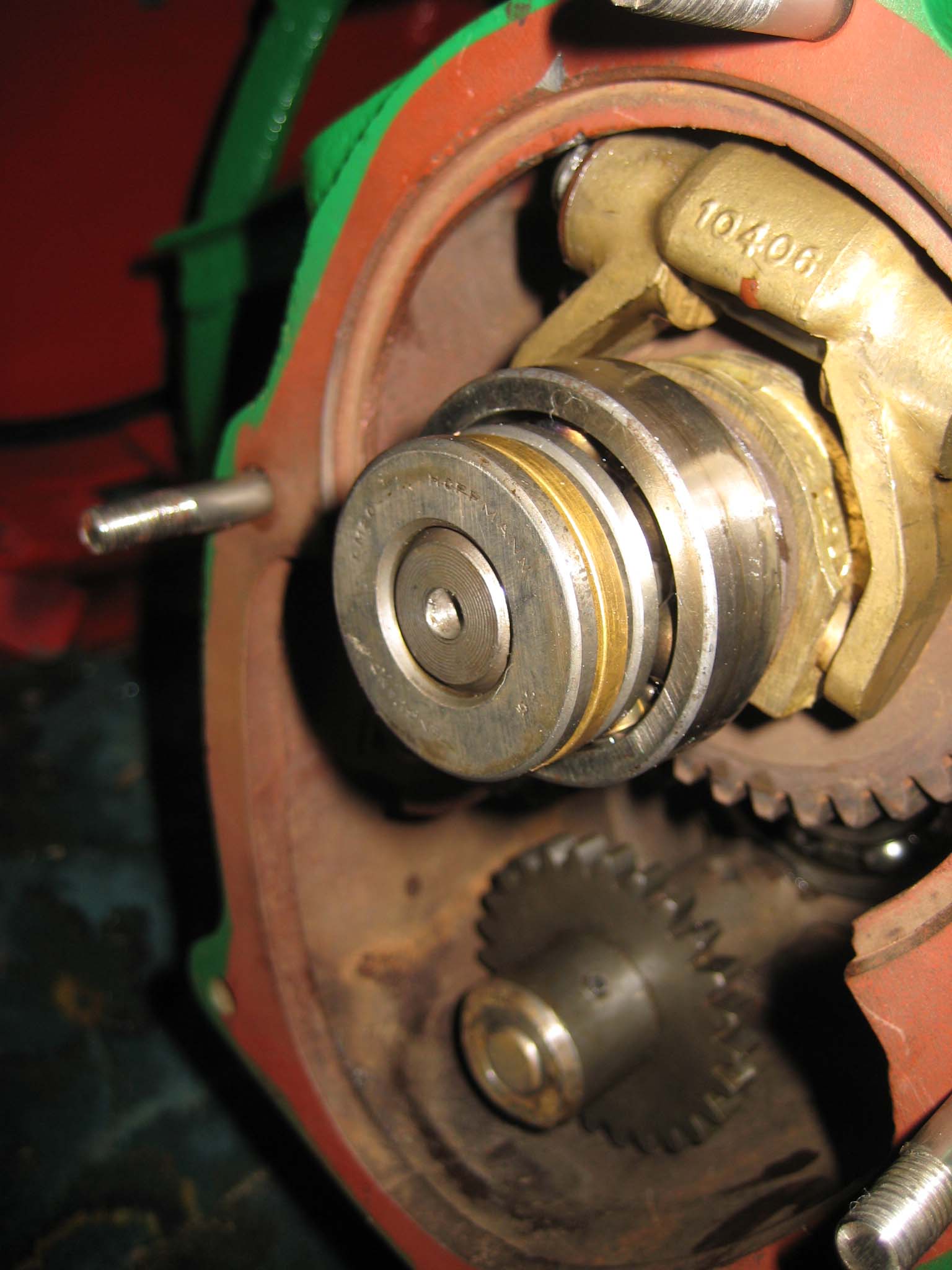
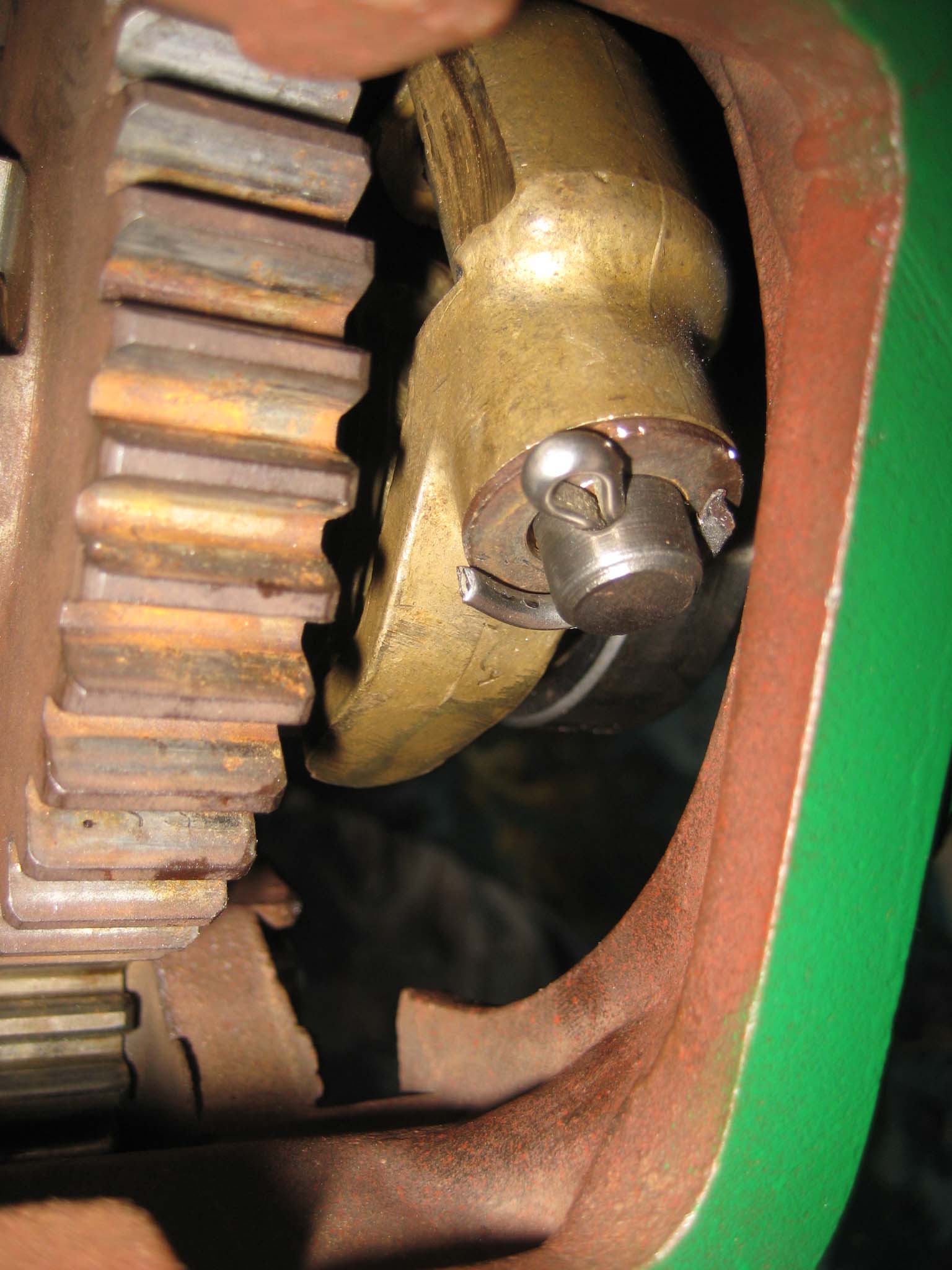
Before the engine could be fitted, there were a few items left to go in the reverse speed gearbox. The roller bearing for the end of the worm drive shaft went in first (Simar 0056), followed by the locking plunger for the reverse gear lever (Simar 0057). I did not fit the actual reverse gear lever at this stage, just in case I needed to manipulate the clutch when fitting the engine. To complete the worm drive shaft, a distance washer and thrust ring are fitted (Simar 0058), along with the clutch fork (Simar 0059). The clutch fork is held on the shaft via a washer and 4 x 20mm split pin (Simar 0060). When the legs of the split pin are bent over, they are very close to the reverse gearbox casing, so check the clutch operation a few times to make sure they don’t foul.Attachments:
October 5, 2015 at 2:30 pm #14757vhgmcbuddyKeymasterFrame
October 5, 2015 at 2:25 pm #14756vhgmcbuddyKeymasterthanks owen and yeah i did wounder filler i also wondered about leaving it and calling it “characteristics” ill see.
October 5, 2015 at 1:47 pm #14755vhgmcbuddyKeymasterOK. The engine is out and in my workshop.
The clutch and flywheel are removed as is the magneto, carbureter and fuel pump.
Fount that the magneto had been repaired in the past. It may require a replacement cap.
It’s still far to heavy for me to lift.
The engine number is MGE 3828.October 4, 2015 at 6:32 pm #14744vhgmcbuddyKeymasterBeautiful machine, thanks for the extra photos Chris.
Very similar machine to the Gyrotiller, but so far as I can glean from the net, no relationship between the two. I have seen a Gyrotiller in the past but not yet the Holt. I’ll eventually make the treck to GDSF, but its a long way from Norfolk!October 4, 2015 at 6:25 pm #14743vhgmcbuddyKeymasterJust to reiterate what Charlie has said, EP oils must be avoided completely. They have an additive which attacks the bronze parts of the gearbox.
-
AuthorPosts