Forum Replies Created
-
AuthorPosts
-
July 3, 2018 at 12:01 pm #28793
 wristpinParticipant
Take the variator off complete with its bracket (that way you don’t have to prise the toothed retainer off) assemble the belts onto it and to the trans and crank pulleys and then replace the bracket pivot bolt and spacer etc.
The trans holding bolt goes back in tight. The front wheel drive assemblies that you refer to either pivot to de-clutch or is under spring tension to keep the belt tight.
The machine that I was working on was suffering from a weak drive and as well as the belts being worn there was considerable wear on the crankshaft pulley – approximately £50+vat for a new one.July 2, 2018 at 12:45 pm #28786wristpinParticipantYes, I’ve got one on the bench at the moment!!!
It’s a bit of a fiddle getting the belt on off and on to the trans pulley but can be done without any major dismantling.
What do you need to know?
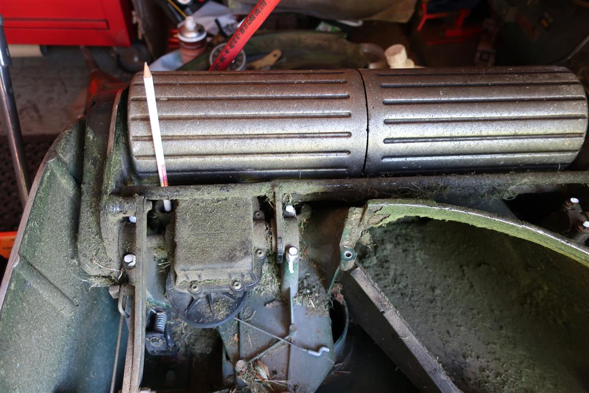
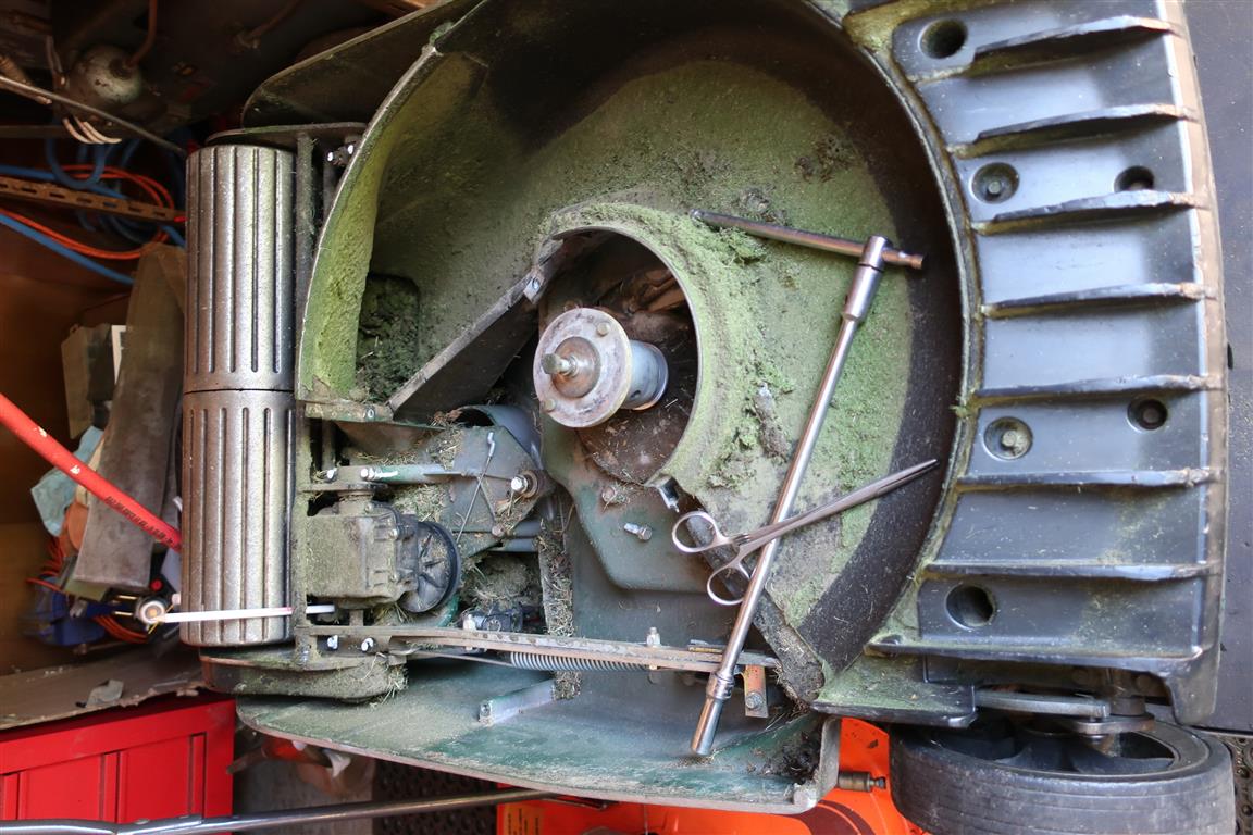
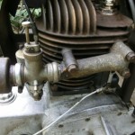
Should add that depending on the model of 56 the trans belts may be 2 x 411024 or 1x 411024 and 1x 111-1254. so checking the part numbers against the model number – for example 560F – is wise.Where the white pencil is on the images is a deep recess in the trans casing with a hex head screw in the bottom. Undo and remove that screw (hence the tweezers) and it allows just enough rock in the trans to make fiddling the belt in or out easier.
Attachments:
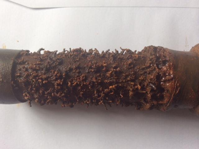
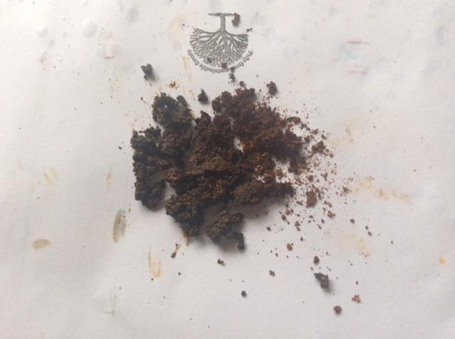
June 10, 2018 at 11:51 pm #28640wristpinParticipantIf you still have the original fuel tap with the gauze filter, there are now two, the combination of which may be causing some fuel starvation. Try rigging the BS tank on a temporary basis with no additional filtration and if normal running is restored, you have the answer.
Internal cleaning of a rusty steel tank can be done by electrolysis and is very effective. Fill the tank with water with a spoonful or two of washing soda and insert the positive electrode through the filler but insulated from it and not touching the base of the tank. The tank itself is the negative electrode.
It may take upto a week to clean it.Attachments:
June 5, 2018 at 10:26 pm #28623wristpinParticipantNone of my engine literature makes any reference to the threads used but perhaps the spanner sizes needed for any nuts or bolts will give a clue. If they require AF spanners, measured Across the Flats, I would suggest that the treads will be UNF and UNC. If on the other hand, they need BSW/BSF spanners where the size relates to the diameter of the threaded component, the thread forms are likely to be BSF and Whitworth. Alternatively, you could check any other threaded components with thread gauges – respectively cheap and always useful.
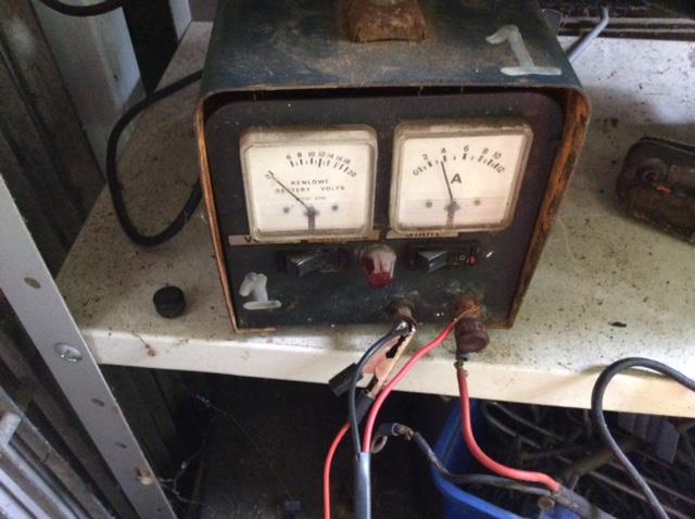
May 31, 2018 at 2:57 pm #28613wristpinParticipantJust remember that you are playing with mains electricity so I suggest that anything that you do should be via a residual current device RCD. Don’t just rely on your household box to protect you – its actually there to protect the house !
If you are determined to fiddle around with it I suggest connecting a short fly lead to the choc bar connecter where you have the white and orange wires connected and plug it straight into your RCD and wall socket.
If it runs ok you have isolated the issue to the mains cable and switch – if not I’d bin it.May 29, 2018 at 11:24 pm #28602wristpinParticipantNot sure about the HS suffix but here is a scan of a Mk15 manual
https://www.dropbox.com/s/2wwwngqeji7m1wy/Villiers%20Mk%20150001.pdf?dl=0May 29, 2018 at 11:21 pm #28601wristpinParticipantCan you be a bit specific about what model you have or even add an image or two? I have the Flymo workshop manuals from the late 70s so may be able to assist.
April 25, 2018 at 8:14 pm #28386wristpinParticipantIt’s been a while but …..Maybe easier to lower the transmission. When I was working on them regularly I used a couple of 4″ lengths of threaded rod and nuts to replace one trans mounting bolt on each side and then remove the other two and the torque brackets to control the drop.
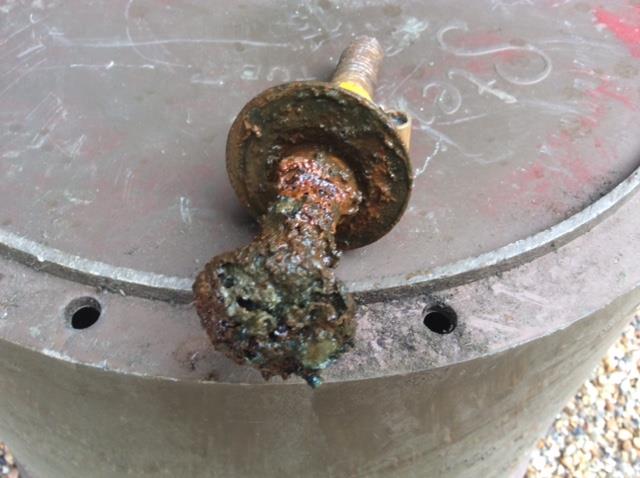
If I remember correctly the pto shaft engages into a plastic block on top of the trans belt pulley – maybe water has got in there and corroded/bonded the shaft into the block.March 29, 2018 at 3:36 pm #28311wristpinParticipantHave you tried using a trolley jack or bottle jack, these would be my first choice.
As above but once lifted settle on an axle stand or stable wooden blocks – just in case.
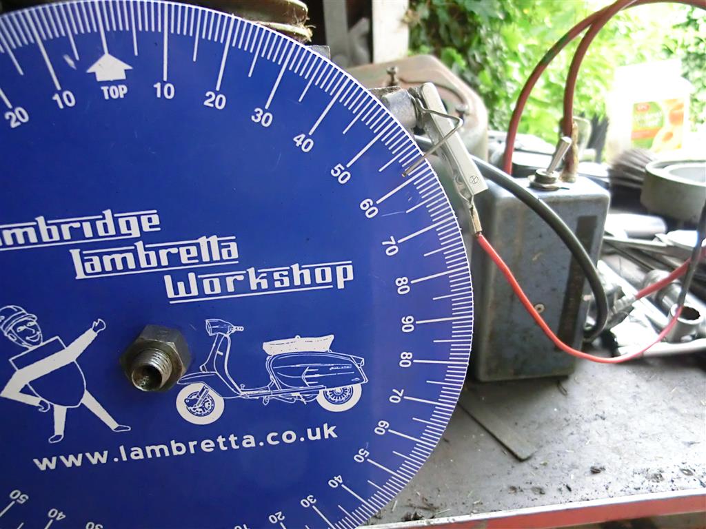
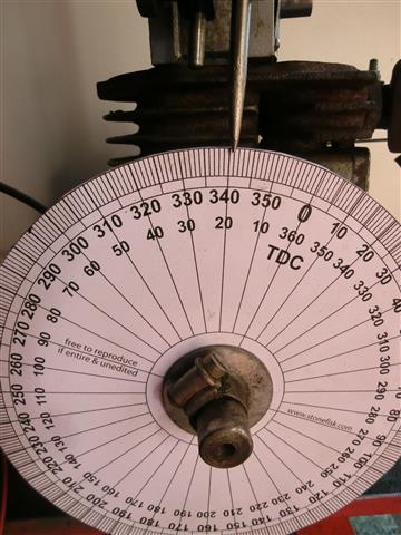
March 6, 2018 at 9:23 pm #28121wristpinParticipant22mm btdc is far too much. You cannot convert the linear measurement into degrees of rotation by a simple pro rata calculation. To do the maths correctly you need to know the throw of the crank and the length of the conrod.
If you are a glutton for punishment, here’s the formulaThe rod angle � is related to the crank angle � by:
R*sin(�) = C*sin(�)
R is the rod length, C is half the crank stroke.
So � = asin(C/R*sin(�))
or � = asin(R/C*sin(�))
The drop of the piston is the rod and 1/2 crank stroke minus each length times the cosine of their respective angles.
Piston drop = R + C – [R*cos(�) + C*cos(�)]
Substitute the equation for � from the above equation:
Piston drop = R + C – [R*cos(asin(C/R*sin(�))) + C*cos(�)]
Solve for � given the rod length, 1/2 crank stroke and piston drop from TDC. You can drop that equation into a spread sheet and plot piston drop versus � then put a trend line through it if you do not want to do the inversion.No, I didn’t do it from memory !!!
A 360 degree timing disk on the crank is the easy and safe method. You can download and print a disc from the net and glue it to a bit of card.
Sending this from the tablet but will add an image from the PC later.
Another thing to remember is that if the magneto incorporates an impulse starter the engine should be turned until the impulse trips and then turned back to set the timing.Attachments:
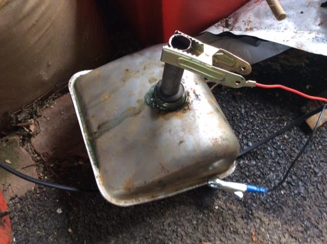
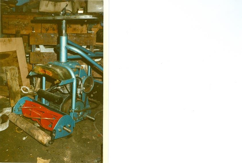
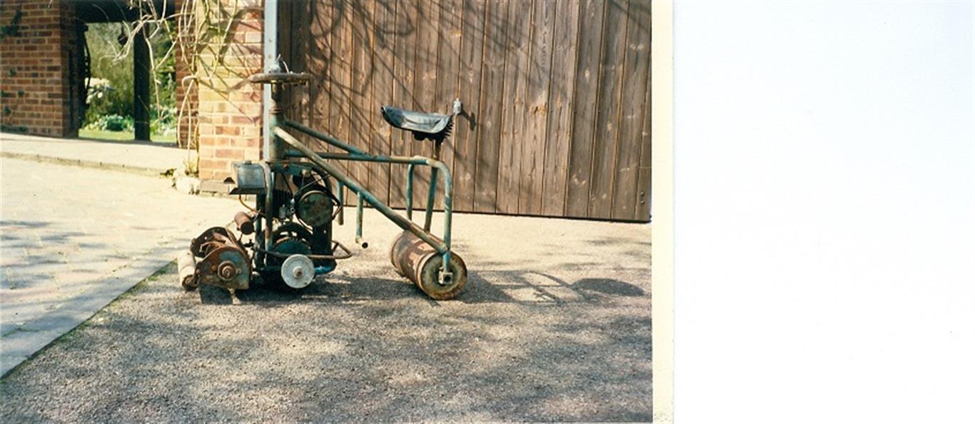
March 4, 2018 at 1:54 pm #28110wristpinParticipantThe Easi-mow, ride on mower, was originally manufactured by EFRanger (Ferring) Ltd in West Sussex, in the early 50s, and was of the “open frame” tubular construction. In the late 50s they sold the manufacturing rights to British Anzani who evolved the original design into the more streamlined pressed steel Lawnrider.
The truck illustrated definitely has Easi-mow origins down to the original shaped fuel tank and the “chain around a sprocket” recoil starter. The attached images are of my part restored Easi-mow.Attachments:
February 26, 2018 at 11:23 pm #28075wristpinParticipantMy Uncle had an M1 identical to this one. His was fitted with Aspera at new, which was an early casualty, he then replaced it with a Briggs 3.5Hp.
A word of warning. The correct spec Briggs for such an application has a “heavy flywheel” . If a rotary mower spec engine is used it will have a light flywheel and in the absence of the flywheel effect of a blade will tend to “snarch your wrist off” when starting !
February 11, 2018 at 10:37 pm #27899wristpinParticipantNot sure about the designation B14 applied to a Villiers engine. Would it be the engine fitted to an Excelsior B14 bike of around 1929?
February 5, 2018 at 11:18 pm #27858wristpinParticipantI have now fitted an electronic magneto but unfortunately broke the pull start return spring
There seems to be a centre bolt holding the mechanism together but it is Very tight and I wonder what the secret to undoing it is?Could it be a left-hand thread? What engine do you have?
January 31, 2018 at 1:20 am #27835wristpinParticipantThis Peerless lubrication chart may be useful in the future. Interestingly there’s no 1216 listed but there is 1316, maybe the chart doesn’t go back far enough or it just comes under the 1200 series?
https://www.dropbox.com/s/98jk0on0inxna53/Peerless%20lube%20specs0001.pdf?dl=0
-
AuthorPosts