Forum Replies Created
-
AuthorPosts
-
January 26, 2017 at 4:55 pm #24179
 trusty220Keymaster
Best of luck with the rebuild. Why not do it as a step-by-step job on the Projects section so the rest of us can help with problems that can occur? It is well worth it if you have the patience to photograph everything then write about it afterwards.
January 26, 2017 at 9:37 am #24175trusty220KeymasterInjectors tend to be made by a specialist company (such as Bosch) and are normally standard items which the engine manufacturers buy in. Most diesel service centres should be able to tackle the job; your best bet is to Google your local diesel service centre.
January 17, 2017 at 9:43 am #24063trusty220KeymasterThe part of the bakelite cap that sticks out should have a knurled knob on it. If you unscrew that you’ll find a thread inside- bare a bit more of the copper on the HT lead and wrap it around the thread in the bakelite cap, then screw the knurled knob back on to hold it in place.
That’s how it should work, anyway! Good luck.
January 4, 2017 at 9:15 am #23880trusty220KeymasterYour best bet is to download a program called “Shrinkpic” off the internet. It just sits on your computer and when you want to post a photo (or email a photo as an attachment) it automatically adjusts the size to something more manageable. I’ve used it for years with no problems.
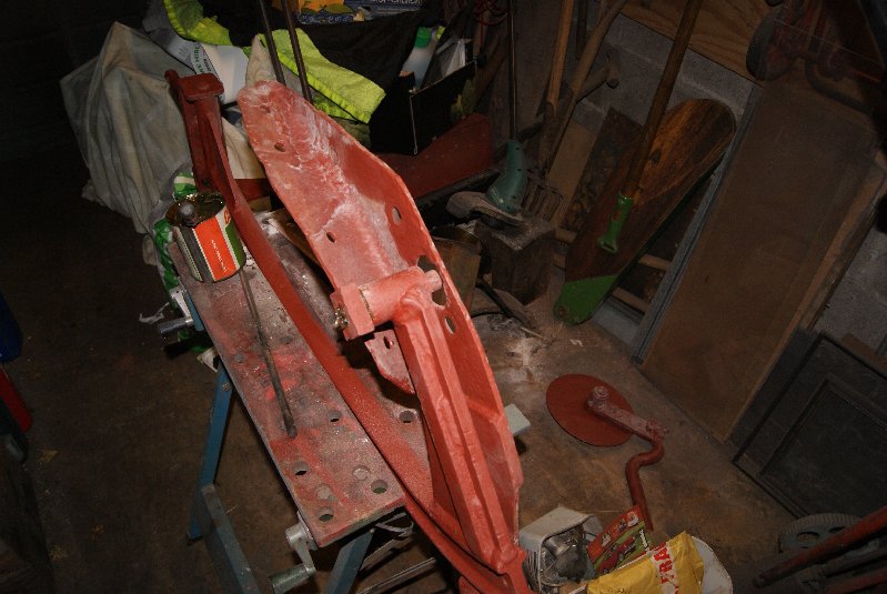
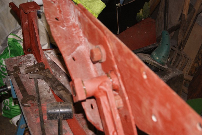
January 2, 2017 at 12:41 pm #23808trusty220KeymasterOnce dismantled I used the pickling process to kill the rust on all the small parts. If you have never done this before it is very worthwhile but takes a couple of weeks to do properly. Firstly I soak the parts in Brick & Patio Cleaner for a week (it is a dilute Sulphuric Acid, so you must do it where you have good ventilation and neighbours that don’t mind the smell of rotten eggs!) then put the parts into a bath of Bicarbonate of Soda for a week to neutralise the acid. It seems to be the second process that fetches the rust off, and if there is any left after the week it is easily removed with a wire wheel on the angle grinder. Generally the steel comes up shiny like new but needs a good clean to be ready for paint. One of the surprises that this brought up was that all of the round spacers seemed to have been almost eaten away with rust so I found myself turning up some new ones before I could re-start the restoration.
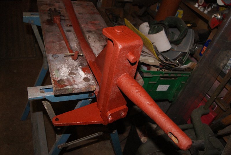
The most logical approach to building the plough up again was to fit the breast to the leg, then bolt the landslide to the breast so that the bottom pivot that I had all of the trouble with could be looked at. Once this was done there is a plate on the side of the beam that limits the plough’s travel that needed to be re-fitted with the first of the new spacers. That completed the back end of the beam for a while whilst I fettle the replacement mouldboard and source a new plough point.
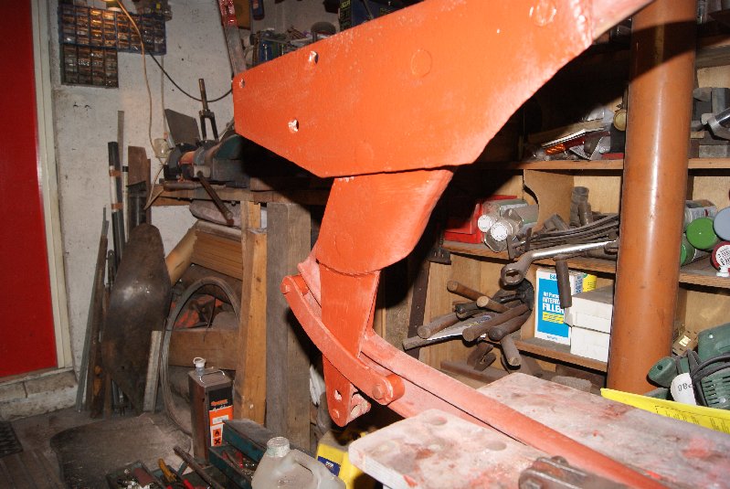
The front of the beam has a similar arrangement to the plough pivot but it works in a vertical plane. The purpose of it is to adjust the furrow width when it is fitted to the tractor, and it also carries the special Trusty Steed fitting to attach it to the drawbar. While the paint was wet at the back I thought it best to re-assemble this as well so that when I turn it right way up again I can re-mount the adjusting levers and connect them.
That’s as far as I got today, so I’ll leave it to dry until I can find time to have another bash.
Attachments:
December 7, 2016 at 9:03 am #23440trusty220KeymasterYou may be lucky- the part that you see through the holes in the wheel does not have the threads in; the threads are in the 100-tooth wheel behind and the circular block that you see when you take the wheel off merely has oversize holes drilled through. This has the effect of lining up the bolts when they are inserted, so it is unlikely that they could be stripped.
Try it first! Good luck.
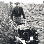
December 6, 2016 at 9:45 pm #23437trusty220KeymasterHere is the picture of the dust cover that I was on about. It is an original factory photo that did appear in one of the tractor brochures.
Attachments:
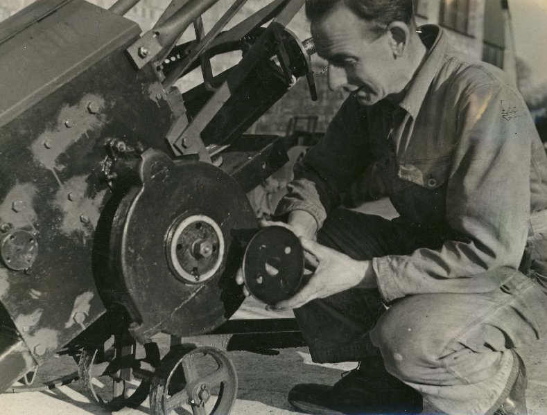
December 6, 2016 at 3:39 pm #23436trusty220KeymasterIf you remove the other two bolts you will find that the wheel will come off easily. What you are likely to find is a whole mass of mud/grease/felt that has congealed behind the hub- don’t worry, just clean it all off with petrol or paraffin so that you can see what you’re working with.
First, have a look at the inside face of the wheel where it meets the hub. It needs to be smooth but most of them tend to be pitted with rust which will tear the new seal if you do nothing about it. The easiest way to overcome a rusty, pitted face is to make a disc out of steel plate and glue it to the inside of the wheel; you can get the diameter of the seal that it has to mate with from the groove around the cast iron reduction gear housing, then add a little more for good luck! Don’t worry, you can’t see it once the wheel is in place and the wheel bolts will hold it in place so you aren’t relying on the glue. Trusty used to make a similar disc that they called a “Dust Shield” which you could buy as an optional extra- I’ll see if I can find a picture of it to post on here.
The seal is fitted to the tractor side and runs around a groove machined in the reduction gear housing. From memory it is 3/8″ square section felt that does the trick.
Whilst the wheel is off it may be as well to find out why the two bolts are missing. Are the threads stripped in the hub? They should be 1/2″ BSF but I forget the length- be aware that if you put a bolt in that’s too long you may lock up the gears or even break the casting at the back, so pay attention to the length and keep rotating the wheel as you tighten the bolts.
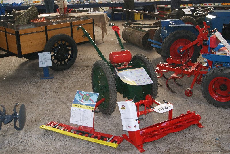
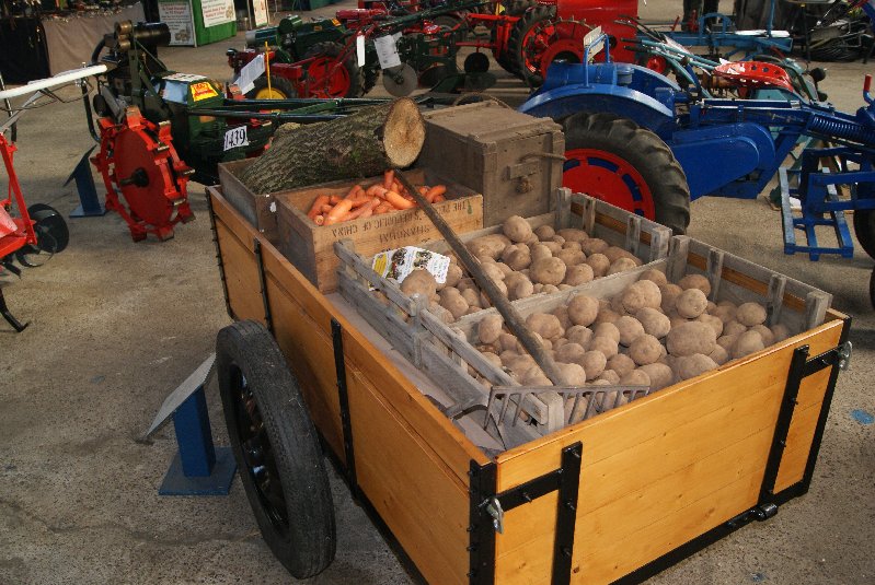
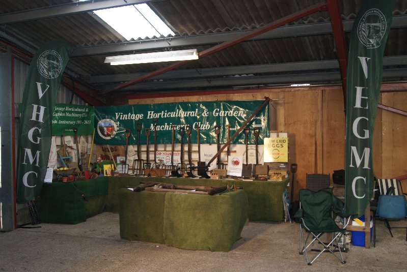
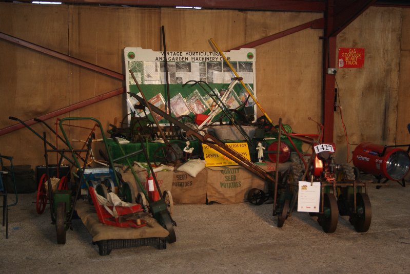
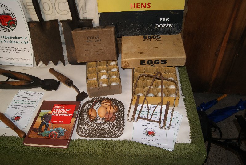
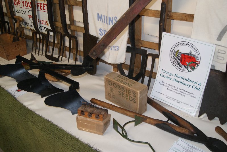
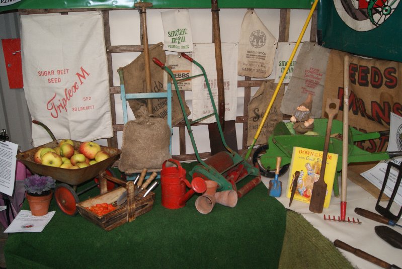
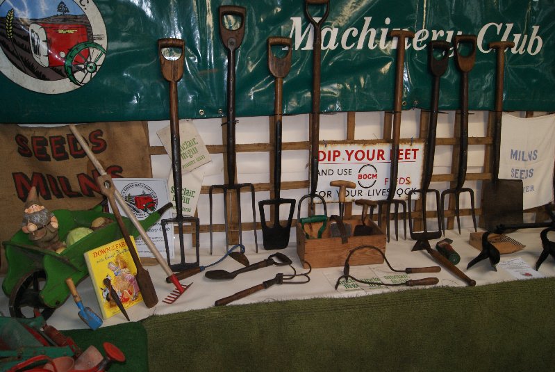
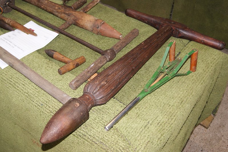
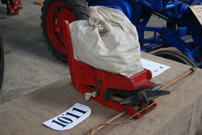
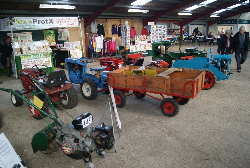
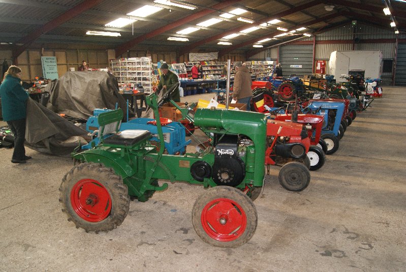
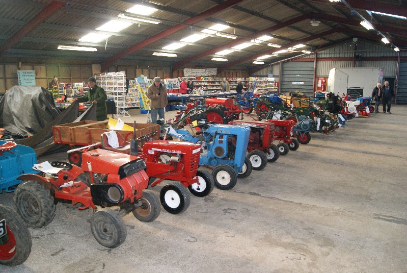
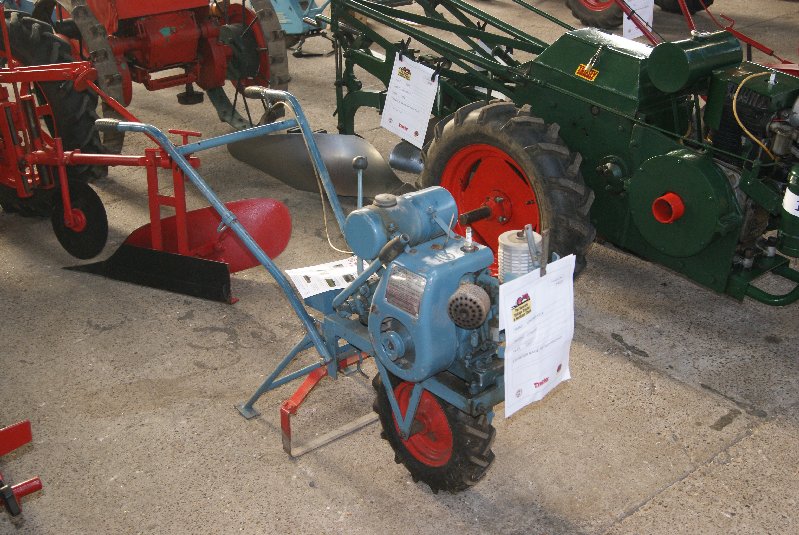
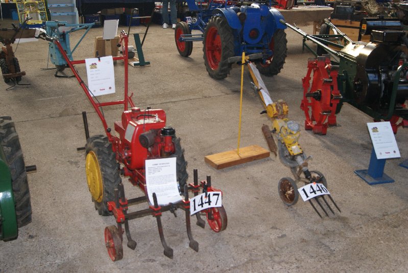
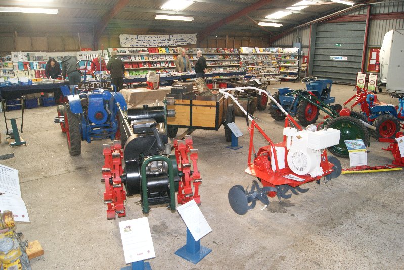
December 1, 2016 at 8:09 pm #23354trusty220KeymasterDon’t panic, here are a few more that I couldn’t get on the previous post! Sandra’s display was very original (and a first!) in that she collected children’s horticultural tools. I never realised that there were so many things made for children to do “our” jobs!
Attachments:
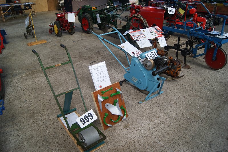
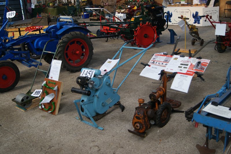
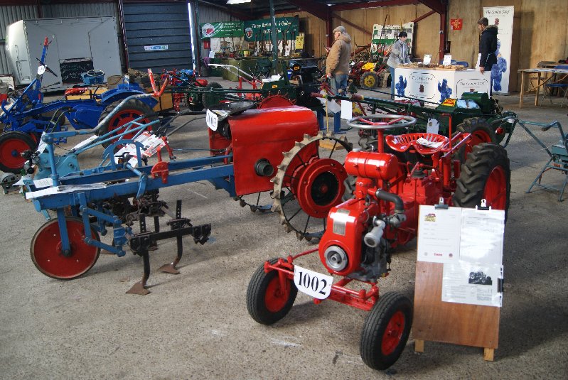
December 1, 2016 at 8:02 pm #23341trusty220KeymasterI do apologise for the lateness of these photo’s but family matters have been my priority for the last few weeks.
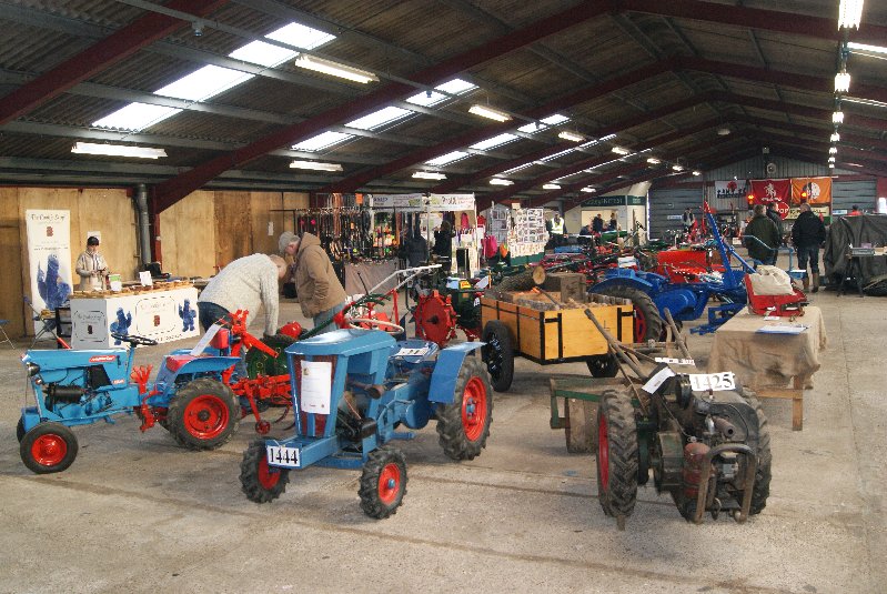
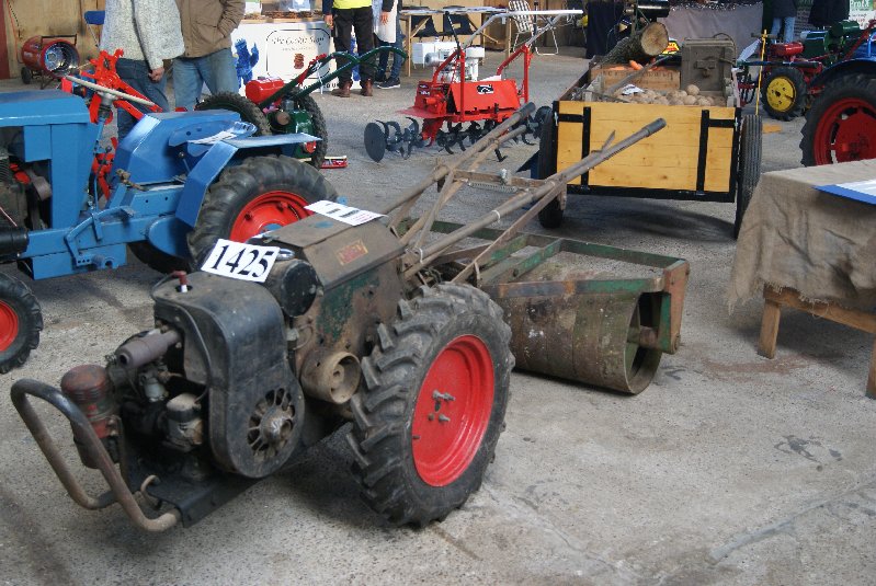
All pictures were taken on the Sunday morning of the show before it opened to the public because that’s the only time you can get to see a clear view of everything. I hope that I’ve captured everything that was in the horticultural section in Crocker Hall 2, but I’ll apologise now if I’ve missed out anyone.
Congratulations to Dave Foster for gaining the VHGMC Shield for best club member’s exhibit and my gratitude goes to Sandra Clark and Steve Woollas for putting on the display on the club stand.Attachments:
November 19, 2016 at 9:21 am #23150trusty220KeymasterThanks for that brief history, Joe. I was nearly right with my ten year guess!
I really must buy your book and read up on the OTA/Singer history.
November 15, 2016 at 9:27 am #23131trusty220KeymasterIt certainly shows how you could build up a nice little collection featuring just one make, and it also shows what a turbulent history these tractors had in their time.
What time span does this collection represent? My best guess is something around ten years’ worth of production by OTA and Singer combined, but then I’m no expert on them.
November 14, 2016 at 2:42 pm #23111trusty220KeymasterI would send the shoes away for re-lining first because the company that I use puts them in an oven to cure the glue. If you put the rubber bushes in before you send them you will very likely have to do the job again when you get them back!
November 10, 2016 at 8:59 am #22981trusty220KeymasterI’m sure Charlie would send you the plans for a small consideration.
November 7, 2016 at 5:30 pm #22916trusty220KeymasterThe shoes are easy enough to remove once you have the clutch carrier removed from the crankshaft. They pivot on a bolt at one end- this bolt has a cone-shaped head that fits into a tapered hole in the arm of the carrier, and there is a self-locking nut on the other end of the bolt. Just undo the nut and push the bolt out, then push the pins out that hold the return springs in place.
I use my local Truckstop to reline the shoes, but most good car accessory shops will offer the same service.
When you replace them on the carrier make sure the shoes are fitted in the trailing position. If you don’t know what it means, look at the carrier from the end that you wind the starting strap on. If you then rotate the carrier in the direction that the engine runs in (anti-clockwise in this case) you need to fit the shoe so that the pivot with the bolt through it leads the rest of the shoe when it turns, leaving the rest of the shoe to trail behind the pivot end. This way the clutch will drive and also disengage when you want it to.
If you fit the shoes in the leading position they will drive but will not disengage. Also, don’t overtighten the nut on the pivot bolt because the ears can snap off the clutch carrier.
Good luck, come back if you need more help.
-
AuthorPosts