Forum Replies Created
-
AuthorPosts
-
October 7, 2019 at 1:49 pm #32165
 wristpinParticipant
Any decent machine shop will make them for you.
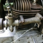
September 20, 2019 at 4:26 pm #32021wristpinParticipantAn image with better definition might answer the question but news print may never reproduce any better ?
Edit
How about this? https://vhgmc.co.uk/forums/topic/jap-16h-landmaster-150-engine-with-161-wipac-mag/September 13, 2019 at 10:31 pm #31962wristpinParticipantFirst, I was wrong about the oil, it should be SAE20 not 30. In the day it would have been Castrolite or another manufacturer’s equivalent.
I knew that I had a very good guide to all things Wico series A tucked away somewhere and I’ve just unearthed it.
http://www.wizardclassics.co.uk/douglas
Maintenance Manual for the Wico Series A.
Edited by and additional content by Peter ChadbundI’ve got another useful booklet which is a reprint of a Wico publication. Reprinted by David W Edgington, Lodge Wood Farm, Hawkeridge, Westbury, Wiltshire.
September 9, 2019 at 10:29 pm #31923wristpinParticipantOil. A few drops of SAE30. Be careful testing for a “ healthy spark” and only do it with a standard gapped plug on the ht lead firmly anchored to the mag base. Waving the ht lead around to create a gap can cause the spark to find an easier route internally resulting in permanent damage.
September 5, 2019 at 3:22 pm #31890wristpinParticipantWARNING!!!!
Much of the JP’s chassis is, I believe, alloy and brick acid will immediately fizz and start eating into it with quite a violent reaction.
I would suggest getting the area around the cotter good and hot with a hot air gun or very carefully with a blow torch. Then putting the nut back on the cotter and giving it a firm hit. The cotters are, I believe, a standard cycle pedal crank part so are cheap and expendable.
At the risk of forum disloyalty, there are a couple of JP experts on the Old Mower Club who have probably encountered the issue and may know the answer.August 26, 2019 at 9:13 pm #31811wristpinParticipantFrom what I remember Murray ( Mountfield) used a couple of different setups for securing the blade but I think that the part number for the nut was 15×72. Chances are that is an old number but may be a starting point. It or it’s replacement may still be current but if you draw a blank try Jon Cruse at the Hailsham Mower Centre; he specialises in old stock for all makes.
Edit. The parts book shows it as 1/2” x 20tpi which is a standard UNF nut size.
August 23, 2019 at 2:55 pm #31802wristpinParticipantCheck the outside perimeter of the flywheel for an arrow stamped into the rim . This arrow was put there on assebly when the factory had timed the engine to make it easier to retime in the future.
First check and adjust the contact breaker points to between 12 and 15 thou.This has to be done with the flywheel in place as the points operating cam is integral with it. Its a bit of a fiddle as it has to be done through the “window in the flywheel. I usually start with a clean 12 thou feeler gauge and settle for a slightly loose sliding fit but having tighten up the adjuster clamping screw just make sure that a 15 thou feeler will not go through the gap. That way its probability 13/14 thou. Having done that pull a clean piece of copy paper through the closed points to remove any traces of dirt. When pulling the paper through, stop before the end so that the points don’t snap down on to the edge and pull out fibres which cause a problem later. Hold the moving point clear of the paper.
The next step is to remove the cylinder head and turn the crank to top dead centre with both valves shut. Then while making sure that the crank does not move turn the flywheel so that the arrow lines up with the small protrusion cast into the magneto back plate.
Tighten the flywheel – very tight – Villiers sold a special spanner designed to be struck with a hammer.
If you have not got a flywheel with an arrow the job is a little more complicated. Set the points gap as above. Then find top dead centre with the valves closed and rotate the crank anti clockwise to lower the piston 3/16″ down the bore. Then ensuring that the crank does not move turn the flywheel so that the points just start to open. The traditional way to determine the “just” was to place a strip of cigarette rolling paper between the points and apply a little tension. “just” is as soon as the points release the paper. Then tighten the flywheel.
Gets easier with practice!August 19, 2019 at 7:33 pm #31791wristpinParticipantLots of modern ride-ons have electric clutches to engage the drive to the blades and these are normally bought in items so it is more than likely that you can find something suitable from a “mower breaker”. Be aware that they can have quite a heavy current draw so the alternator capacity of your “ found” engine needs to be sufficient. If your engine’s original application did not have an electric clutch, you could have a problem.
August 19, 2019 at 7:26 pm #31790wristpinParticipantMore information required – what model Villiers engine? I presume that you are referring to ignition timing and not valve timing ? Some engines have their flywheels keyed to the crank so the basic timing is set by design. Others have the flywheel secured on its taper with no key and it has to be positioned in relation to the piston position – slightly more complicated.
So, what have you got, images are always useful.August 16, 2019 at 3:28 pm #31767wristpinParticipantDennis did come from Guildford and they did make a set of mini gangs that were known as Guildford gangs – as in Premier and Paragon cylinder mowers etc. That said, if it is from a gang I would expect it to have a rubber tyre. I think that you could well be correct in thinking that it is the remains of a small side-wheel push mower that was made for a specific retailer – as was the practice of the day.
July 23, 2019 at 8:37 am #31629wristpinParticipantAs a non running cultivator – not a lot but as the missing link in a collection , a bit more. Not very helpful but it all boils down to what someone is prepared to pay on the day. To be correct it is a Kirby Lauson, not Lausen. They were an Australian built version of a Lauson / Tecumseh engine and Mountfield fitted them to cultivators and rotary mowers in the 1950s. I don’t know for sure but I suspect that coming from a Commonwealth country they attracted less import duty than the USA made products.
It shouldn’t be too much of an issue to get it running as it shares ignition components with more common Tecumseh and Aspera engines.July 22, 2019 at 5:17 pm #31625wristpinParticipantThis may be useful
https://www.dropbox.com/s/jcfefidm75gl4kq/HOWARD%20300%203500001.pdf?dl=0
Item 15 / 68908, Clutch cone inner and liningIf you have a very early 300 I have a vague recollection that they had a “fibre” thrust pad to disengage the clutch rather than a ball race as in the illustration. I believe that there is a firm that supplies some older Howard clutch parts – hopefully someone else has a better memory!**
Fairly certain that the original engine would have been a Kohler.
** edit – these people!
https://howard-rotavator-spares.com/products/index.php?cat=1July 15, 2019 at 6:03 pm #31581wristpinParticipantIf your machine has a Briggs and Stratton engine it’s as well to be aware that the blade carrier discs came with two sizes of boss, one for the crank on the 3.5 hp domestic machines and a larger one for the crank on the 5hp Professional.
June 29, 2019 at 3:40 pm #31504wristpinParticipantPerhaps you should be aware that all the available mowers will fill all the available space!
EnjoyJune 29, 2019 at 3:36 pm #31503wristpinParticipantThat makes sense. I think that the Westwood badged Dynamarks had the pressed steel decks as per your images and the first Plymouth built machines had the fabricated decks; the 28” one being known as the the-penny-bit deck.
Now I wonder why ?! -
AuthorPosts