
Forum Replies Created
-
AuthorPosts
-
March 11, 2018 at 4:42 pm #28142vhgmcbuddyKeymaster
Thanks Andy
Being local it was too much to resist! It’s currently sitting on the Commer as I’ve no space for it. IF, and it’s a big if, the weather dries up a bit I’ll probably have it out at Stanfield next week. I imagine it’s pretty claggy underfoot at the moment.
PeterMarch 11, 2018 at 3:00 pm #28140vhgmcbuddyKeymasterA short video from today.
Anyone got a spare black cover for the top of the handlebars pivot? Don’t think much of the current solution!March 11, 2018 at 2:36 pm #28137vhgmcbuddyKeymasterJust when you think you’ve missed the boat, you hear of the very machine you want being available locally. Suffice to say now safely tucked up at home, with one very happy owner!
Attachments:
March 11, 2018 at 12:53 pm #28134vhgmcbuddyKeymasterI believe it is a jap 80cc
March 10, 2018 at 6:44 pm #28129vhgmcbuddyKeymasterChris,
Thank you too; all good info!
Tony
March 10, 2018 at 6:43 pm #28128vhgmcbuddyKeymasterTed,
Many thanks; will give it a go!
Tony
March 10, 2018 at 3:49 pm #28127vhgmcbuddyKeymasterChampion D16
Available from “the Green Spark Plug Co.”March 9, 2018 at 7:34 am #28124vhgmcbuddyKeymasterPost the gear-box number on here 😆
March 6, 2018 at 9:23 pm #28121vhgmcbuddyKeymaster22mm btdc is far too much. You cannot convert the linear measurement into degrees of rotation by a simple pro rata calculation. To do the maths correctly you need to know the throw of the crank and the length of the conrod.
If you are a glutton for punishment, here’s the formulaThe rod angle � is related to the crank angle � by:
R*sin(�) = C*sin(�)
R is the rod length, C is half the crank stroke.
So � = asin(C/R*sin(�))
or � = asin(R/C*sin(�))
The drop of the piston is the rod and 1/2 crank stroke minus each length times the cosine of their respective angles.
Piston drop = R + C – [R*cos(�) + C*cos(�)]
Substitute the equation for � from the above equation:
Piston drop = R + C – [R*cos(asin(C/R*sin(�))) + C*cos(�)]
Solve for � given the rod length, 1/2 crank stroke and piston drop from TDC. You can drop that equation into a spread sheet and plot piston drop versus � then put a trend line through it if you do not want to do the inversion.No, I didn’t do it from memory !!!
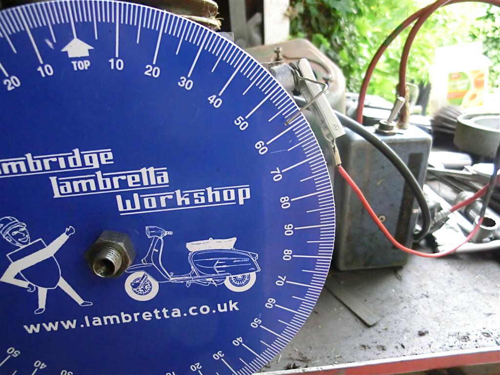
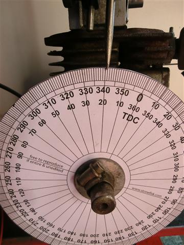
A 360 degree timing disk on the crank is the easy and safe method. You can download and print a disc from the net and glue it to a bit of card.
Sending this from the tablet but will add an image from the PC later.
Another thing to remember is that if the magneto incorporates an impulse starter the engine should be turned until the impulse trips and then turned back to set the timing.Attachments:
March 6, 2018 at 8:09 pm #28120vhgmcbuddyKeymasterAndy, in the manual posted by Charlie and Rod, it states rotate the engine back from TDC by 38 degrees. If the engine has a stroke of 104mm for 180 degrees of crank rotation, 38 degrees works out at 22mm down the bore, not far off an inch, which agreed sounds way too advanced. Maybe a mistake in the manual??
Sorry Tim, can’t help identifying the engine from the numbers you posted. Maybe post a photo or two so we can be sure we are all talking about the same model of engine?
Sean
March 5, 2018 at 11:09 pm #28117vhgmcbuddyKeymasterAh! Thanks Busman – seeing as the head comes off so easily i was thinking there has to be a simpler/more accurate way to get the points opening at the right point of compression than dicking about trying to measure degrees of rotation etc – it would be far more accurate to simply take of the head, measure down the bore that specific distance to the point of optimum compression and set the spark to come then.
As it is – having measured it by 38degrees rotation from TDC by my method described above, the cylinder is a good inch or so down the bore and this seemed too great a distance – not actually achieving a decent level of compression. Now your manual talks about 1/4″ I’m even more suspicious that what i’ve set it to can’t be right….
How can i tell what model of engine it is? The number 81020/4 is stamped on the engine cowl, but there is nothing stamped on the brass plate riveted to the “stone flap” at the back of the machine, it’s just blank…
My engine has a solid copper head gasket on which i was advised to simply heat to cherry-red with a blow torch, quench, then install -thereby “annealing” it – which I didn’t do as i didnt have a blow torch down the allotment…i just put it back together – it’s dry, no gasket sealant and didnt seem to be before either….
At the moment, there’s no spark so i’m going to try and sort that out – if i get it sparking I’ll give it a go as it is (set at 38degrees back from TDC) and if that’s really ropey then will re-do it 1/4″ down the bore….
It must just be me but i am sure the manual could have been written in a more straightforward manner.
March 5, 2018 at 8:29 pm #28115vhgmcbuddyKeymasterJust to confuse matters, the manual I have differs from what has already been provided by Charlie and Rod, stating that the points should commence to open 1/4″ before top dead centre. Don’t know how many versions of JAP engine were available for the Gem and if my manual applies to your engine.
Attachments:
March 5, 2018 at 7:57 am #28113vhgmcbuddyKeymasterMade some progress i think…
Took the cover off to the chain drive between crank / magneto and was able to take off the crank sprocket/chain. Made a little plastic indicator out of a plant label fixed to the crankshaft with the nut, and then turned the starting handle to rotate the engine through the compression stroke to TDC, and then wound it back 38degrees.
This translated as about an inch in travel down the bore – does that sound about right?
I then rotated the mag shaft until the points were just starting to open.
Put it all back together.
whizz the handle…
No spark at the mag…. the cap doesnt have a screw to hold the HT lead in place, i think it must be a push-fit, but as the HT lead itself doesnt have a brass ferrule crimped to it, it was just held in place with masking tape – so i think that needs some attention first, but with the amount of cable exposed and pushed into the mag cap it should still have been okay.
I’ll get a little wet-n-dry paper and try and clean up the points, and may as well get a new spark-plug too…
then take it from there…
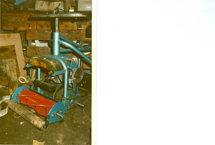
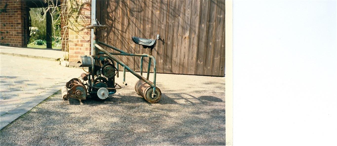
March 4, 2018 at 1:54 pm #28110vhgmcbuddyKeymasterThe Easi-mow, ride on mower, was originally manufactured by EFRanger (Ferring) Ltd in West Sussex, in the early 50s, and was of the “open frame” tubular construction. In the late 50s they sold the manufacturing rights to British Anzani who evolved the original design into the more streamlined pressed steel Lawnrider.
The truck illustrated definitely has Easi-mow origins down to the original shaped fuel tank and the “chain around a sprocket” recoil starter. The attached images are of my part restored Easi-mow.Attachments:
February 28, 2018 at 3:14 pm #28083vhgmcbuddyKeymastergood move,
read as much as you can.
you are asking the right questions, it will work well when fixed.whole book, there several editions.
https://www.dropbox.com/s/8lnthdz07lflmz1/Engine%20Gem%20JAP%20600cc%20MK%20II%20Engine_Instruction%20%26%20Parts%20List.pdf?dl=0serial number as stamped into top of main frame pipe is how to date.
should be on the brass plate on rotor cover too.
then see howardgem.webs for approximate date, see where it fits in the list there.
post sn here with a pic or 2?cheers Rod.
-
AuthorPosts