Forum Replies Created
-
AuthorPosts
-
July 16, 2014 at 1:04 pm #9278
 trusty220Keymaster
A couple of years ago I took my Norton Trusty to Holbeach working weekend for Steve to push around whilst I was ploughing with another one. When I arrived I unloaded it, started it up (first time as always) and parked it up.
“Let me put a drop of the good stuff in”, says Steve, so (like a fool) I let him. I started it again for him (first time again) and drove it about ten yards, just long enough for the engine to pull “the good stuff” through then it stopped and refused to start for the rest of the day.
7a.m. Sunday morning saw me dismantling and cleaning it so that I could put some fresh petrol in to use it myself. With fresh petrol it worked!
No doubt Steve will have a different angle on this story, probably involving ladies of the night and Fenland Mountain Rescue, but it’s all lies!July 13, 2014 at 5:59 pm #9234trusty220KeymasterWhen it is fully clockwise the butterfly is in position 2 (i.e. it is in line with the airflow). The choke position does not exist as such- mine starts with a tiny bit of throttle and the cold starting aid is the primer on the float chamber. If you depress this until a stream of petrol comes out of the two air vents on the float chamber lid then pull the strap to start it you are normally rewarded with a nicely ticking-over engine.
A cautionary word, though- don’t let Steve Woollas anywhere near it, it’ll never work properly again!
Best of luck with it, I think you’re nearly there.July 10, 2014 at 6:02 pm #9156trusty220KeymasterI’m sorry that I didn’t see this at first, Sean, I’ve been a bit busy building the Ploughing section and the Garner Registers- I hope you like them!
Anyway, throttle settings on the Amal fitted to a Norton Big 4, here goes.
Use the closed butterfly as your starting point; set the twist grip throttle to the fully anticlockwise position, then you need to adjust the dog-leg at the end of the throttle rod so that it is offset towards the carburettor (you do this by undoing the clamp in the throttle rod joiner, adjust the dog-leg at the end, then tighten it all back up).
The carburettor link should now be pushed towards the carb by the dog leg, so that now all of the linkage should be in the tick-over position. After double-checking that the butterfly is in the fully closed position, tighten the clamp on the arm around the throttle spindle so that the whole lot is now tight and set at tick over.
The engine will not work at this setting with the butterfly fully closed because no air can be admitted, so we now need to open the butterfly slightly using the tick-over screw clamped to the throttle spindle- I use about 1/16″ gap as a starting point.
The main jet needs to be screwed in fully (gently!) then backed out by one turn. The tick-over mixture screw also needs to be turned fully home, then backed off by one turn. This should at least make the engine run so that you can tune it by ear.
Somewhere near 95% of the fuel goes through the main jet, so we set the main jet up by running the engine at about 1500 revs and turning the main jet in and out until smooth running is attained with no misfiring or banging, or excessive black smoke.
Turn the tick-over speed screw in a few turns so that when you drop the revs to about 1,000rpm the engine will be running on the tick-over screw; this will allow you a lot more control when you come to set up the slow-running jet.
You should now have the engine running at 1,000rpm with the screw touching the carb. barrel. Next you can slowly turn the revs down by unscrewing the tick-over screw slowly; as the speed drops then the slow-running jets alongside the butterfly start to take over and become more important. By using your ear to listen to the engine’s behaviour you should be able to adjust the slow-running jet at the front of the carb to achieve an even, balanced tick-over. Just remember that turning this jet outwards will admit more air to the tick-over mixture and thus weaken it down, turning it in richens it up; at this point do not touch the main jet, however tempting it may seem! If you do then you will have to start all over again.
When you get near to the correct speed for tick-over you will hear the clutch drum clanging like a bell; this is caused by the clutch shoes becoming disengaged. Adjust a little slower than this until you can see the end of the countershaft stop spinning.
You’ve done it!
It takes a lot longer to describe than it does to actually do the job, but be prepared to get it wrong a few times before you reach a setting that suits you and the machine.
Best of luck.July 8, 2014 at 5:32 pm #9069trusty220KeymasterIf you need any help you can pick my brain- I used to look after a fleet of them in the 1980’s and used to know every nut and bolt on them. The 2055 MAG was a particular favourite of mine and came in two versions on the Motor Triple; the only differences were in the carburettor and the distributor.
A word of warning, though. If you do manage to find an original book for the engine there are two mistakes in it:-
1. The torque for the head studs should be 40lb/ft whereas the book says something like 25lb/ft- you will end up with lots of blown head gaskets if you use the value given in the book.
2. If you follow the setting up procedure to time the distributor/oil pump drive then you find that the distributor is timed 180 degrees out; easily fixed- you just swap the spark plug leads over from left to right and right to left (it is only a 2-cylinder engine), but it looks messy.I hope you have fun with it and any problems come straight back here, we would all love to help!
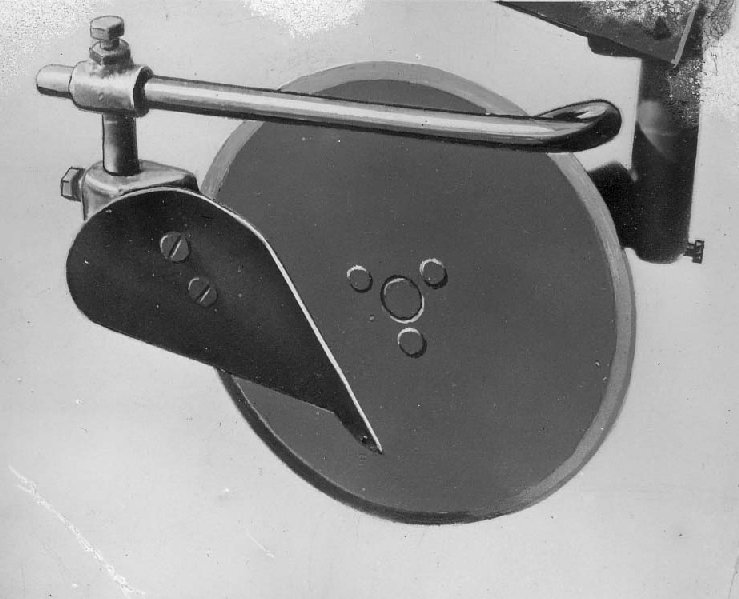
July 7, 2014 at 8:06 pm #9027trusty220KeymasterQuite a few of the plough makers in the 1980’s experimented with slatted mouldboards as a way of minimising the friction ( and hence the power needed to pull the plough) so that they could use a smaller tractor or add another furrow; this plough is one that was used on a very low-powered machine and so friction would have been a major problem. The slats also had a beneficial effect on the finished seedbed because they would break up the soil if you travelled fast enough, thus doing away with further costly field operations.
It should do a good job- let’s see the pictures of the results, Alan!June 26, 2014 at 4:05 pm #8803trusty220KeymasterI suppose he’s going to tell us that the Trusty Imp restoration is all his own work! Now we know the truth.
June 16, 2014 at 6:53 pm #8685trusty220KeymasterShe’s not getting broody is she, Ivan?????
June 10, 2014 at 6:05 pm #8602trusty220KeymasterThere seems to be an ominous silence from our Treasurer. You don’t think she’s………?
June 8, 2014 at 5:38 pm #8578trusty220KeymasterFor the point most people tend to use a Ferguson one. The only trouble is that the frog (the piece that the point bolts to) is a very close fit to the underside of the point, resulting in the point not lining up when it’s bolted in. If this happens the best thing to do is to shave some off the inside face of the point until it fits properly. I’m told that you can also use a David Brown one, but I’ve always stuck to Ferguson pattern.
The standard disc is around 12″ diameter, but you can use a larger one for the opening and the finish. The standard one is best to stick with because you can then use a skim with it to bury the surface rubbish.Attachments:
June 8, 2014 at 5:10 pm #8576trusty220KeymasterI will add it to my “To do” list.
June 8, 2014 at 5:05 pm #8574trusty220KeymasterIs that another one that Steve is trying to sneak past the kitchen window, then? I think he got into enough trouble last year at Newark when he was accused of buying more stuff without letting his better half know.
Just to add a bit of scale, here is the picture of Steve with a man’s spade, so he should be just about the right size for the Webb!Attachments:
May 29, 2014 at 9:07 pm #8425trusty220KeymasterAs far as I know, no risk to you at all.
GeoffMay 29, 2014 at 6:07 pm #8409trusty220KeymasterI have just deleted the entries, but if there are any more please let me know and I’ll do the same to those.
May 16, 2014 at 7:14 am #8111trusty220KeymasterSisis is still in existence and they are pretty good at supplying parts for older machines. You can find them easily if you Google them.
I’m pretty sure that you could get a range of tines for it; the most unusual were the Root Pruning Tines which were straight knife blades.May 16, 2014 at 7:09 am #8110trusty220KeymasterThere should be a groove pressed into the metal of the base that you have taken the photo of. The groove goes all the way around it- that is the level of oil that you put in. There should be some holes in the centre baffle that let the oil flow through from the outside to the inner ring so that the level is the same in both outer and inner.
-
AuthorPosts