Home › Forums › Groundcare Machinery › Grass Cutting Machinery › Oxford Allen Scythe Villiers Mk25c
- This topic has 29 replies, 6 voices, and was last updated 1 year, 3 months ago by
forger0n.
-
AuthorPosts
-
February 7, 2025 at 9:42 pm #43337
forger0n
ParticipantGood evening from a new participant.
I have an Oxford Allen Scythe which worked OK about 14 years ago, but now seems to need magneto
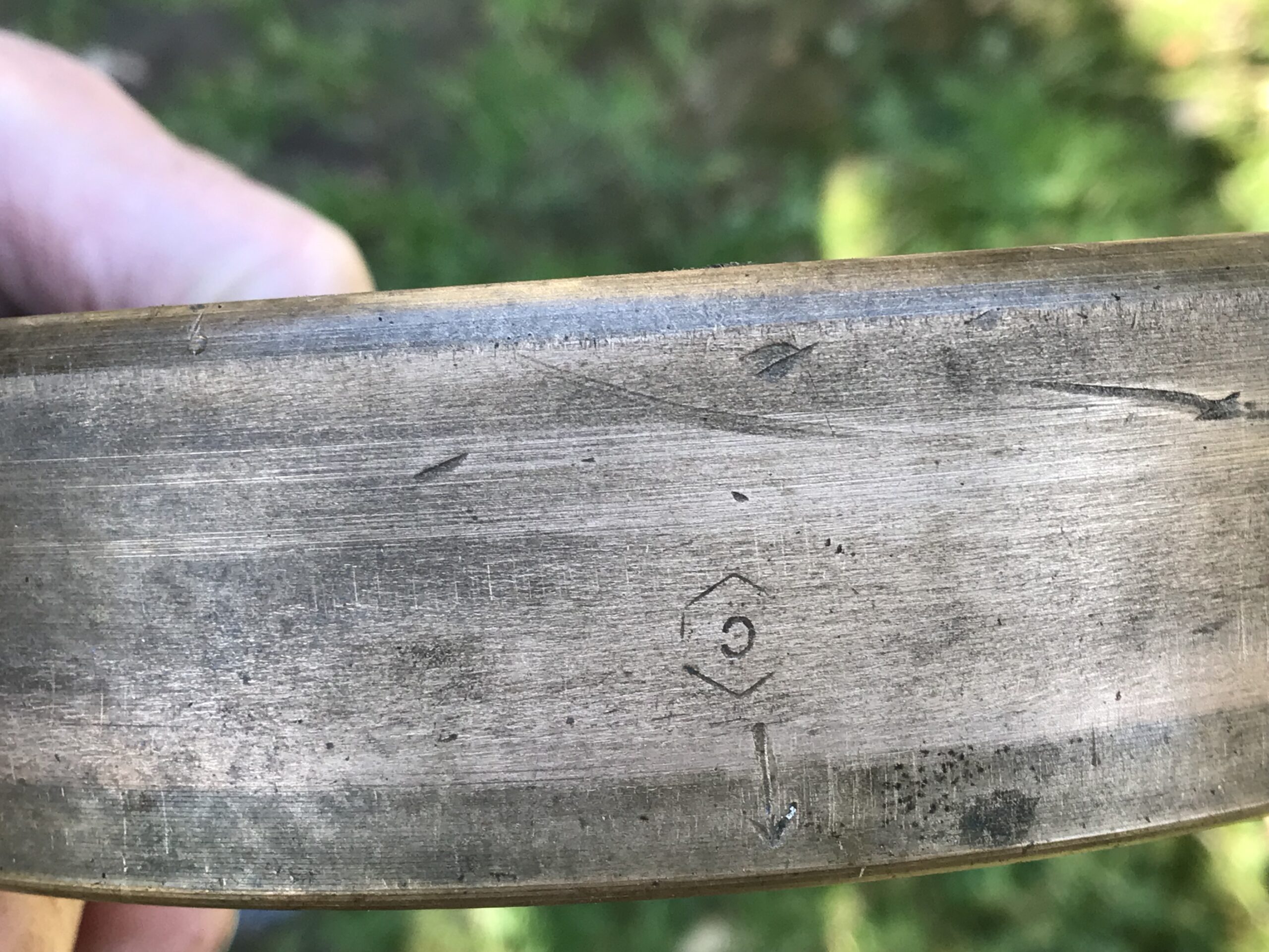
refurb. Those in the know will understand that to remove the ign. coil I have to remove the Armature Plate. To do that I have to remove the flywheel assembly, and all efforts have so far failed. I’m thinking that I will have to destroy the flywheel to get it off, and then I will need a replacement. Looking for a flywheel for sale, they mostly have a reference No. stamped on the rim. Mine has no marking except for an arrow and <c> (for timing, no doubt) – see attached.
Can someone please help me to identify my flywheel. I have a parts list for the magneto which shows four options for the flywheel assy. and none of the numbers relate to those I have seen on the internet. The machine No. is 61747 – no sign of an engine No.
With apologies to the Purists : I had thought of rewiring the magneto to fit an external ignition coil and capacitor, as in car engines, powered by a rechargeable battery as per portable hand tools with the contact breaker still operated by the cam on the flywheel shaft. At least this would not upset the timing.
Thank you for reading all of this , and thankls inadvance for any guidance
Dave SeabrookAttachments:
February 8, 2025 at 7:33 am #43339andyfrost
ParticipantIt’s a shame you didn’t post before trying to remove your flywheel , we could have helped with that. They are “self pulling” ,the nut will loosen , then go tight again , then use a CORRECT size socket and hammer to continue undoing the nut and it will pull the flywheel off , if you have one , an impact gun will do it in seconds but it sounds as if it is too late for that. Any flywheel from a 25c will fit and do the job , although the original Allen ones had a centrifugal govenor cam fitted , they will work OK without it. George at villiersparts may have something that will do the job , other than that it’s a matter of keeping your eye out for a secondhand one.
Andy.
February 9, 2025 at 7:04 am #43340ParticipantMany thanks Andy for your post. A friend of a friend told me about the clever captive nut in the flywheel assembly, and I also found a S/H slogging spanner of the right size. The slogging hammer certainly shifts the nut – to the extent that in anticlock mode it seems to have stripped the thread of the nut &/or the crankshaft. Before running free it had deformed the centre of the bronze part of the flywheel My last attempt will be to borrow a big bearing puller.
I’ll look up George at Villiersparts.
Thanks again for your helpDave
February 9, 2025 at 10:35 am #43341 sidevalve5Participant
Hi Dave,
When undoing the flywheel nut, there is a few turns when the nut feels free, where it transitions between tightening onto the crankshaft and starting to pull the flywheel off the taper. It then goes tight again and if you continue to turn or hit the spanner, it almost has the feel of a thread stripping. But it is just the action of the flywheel pulling off the taper. If the nut turns free for several turns but the flywheel is still firmly on the crankshaft. Then you will have stripped a thread and would hope its not on the crankshaft.
Have read with interest your ideas about fitting and external coil and battery. About 14 years ago I purchased a Clifford Mk1 that was in great condition, except there was no spark. The vendor was very up front about it and said he thought the coil was duff. He said it may be possible to fit an external single wire energy transfer coil, similar to a Honda C50. He was right about the failed coil, so did some research and decided to have a go. The system was developed by trials riders in the 1960’s, whose Villiers engines had reliability problems. They stripped the secondary windings off the ignition coils, linked the primary with the lighting coil and fitted a 6v external coil. Without a lighting coil, I just stripped the secondary windings and attached the single wire to the external coil to the hot side of the points. No spark, so gave up on the idea and got a replacement from Villiersparts. It was not an exact copy and needed a bit of work to fit. But the results were a good fat spark.
I now know why my attempt of fitting an external coil did not work. The voltage generated by the primary winding was not enough to induce a spark. It is why the 1960’s conversion used two coil windings. In an ideal world the ratio of primary to secondary windings should be 1:10. The method I should have done was to strip the coil completely and rewind the primary using 22swg enamelled wire, putting 350-400 turns on the soft iron core. Still have the external coil, it was I recall only £12 and have vouched that the next time I have a duff coil. I am going to have another go at fitting it. The advantage being that the voltage generated by the primary will create stronger lines of magnetic force within the secondary. At the moment of flux reversal and when the points open, the magnetic field rapidly collapses. The voltage produced will be greater, therefore a bigger spark at the plug.
However, all of the above may be superfluous to you. Once you get the flywheel off, you may just clean and adjust the points and job done. I like to obtain a spark at 6mm air gap and use a cheap adjustable spark tester for this. 4mm is OK, it will run, but starting and tickover is better with the greater gap. If no or weak spark, then get a multimeter and test resistance. HT continuity should be 3000 – 7000 ohms and LT 0.5 – 0.7 ohms. If you are inside these ranges but still no or a weak spark, then in all likelihood the coil is OK, but the condenser if duff. This can be tested, but will need a megger to check the insulation resistance is 200M ohms. Its probably better to replace it and I would fit a modern capacitor. I fitted one from Brightsparks with fantastic results, all of the above test figures and methodology I obtained from them too. They have a brilliant website that goes into magneto ignition in great detail. Note that Villiersparts sell a modern condenser, but do not know its specification. Subsequently I have got some polyester film 630v 220nF/0.22uF capacitors and fitted those. Again with brilliant results.
Best of luck with everything.
Grahame
February 9, 2025 at 11:26 am #43342ParticipantDave , if you’re saying the nut turns freely(by that I mean continuously) , it is more than likely stripped thread in the nut itself , seldom if ever will it strip the crankshaft thread. I’ve had this happen before , and it boils down to how much time and money you are preparde to throw at it. I have managed to cut the flywheel off , but it takes great care so as not to damage the crank. I can personally vouch for the new coils from villiersparts , they produce a better spark than the ones I used to fit as a youngster when working for a villiers agent , same as his condeners.
Andy.
February 10, 2025 at 11:44 am #43343sidevalve5ParticipantHi Dave,
Had another idea that may solve your problem. If the HT and LT continuity tests are fine, you could fit an external Meco transistor ignition unit. If you can get to the wire terminal on the hot side of the points, you could disconnect them and connect with a wire fed from the Meco unit though the back of the armature plate. The Meco module dispenses with the points and condenser. It works by ‘sensing’ flux reversal when the flywheel magnet passes from north to south over the coil’s soft iron core. This is when the points would start to open, the Meco unit has a transistor that does the same action. Namely stopping the flow of electric current to the primary windings. Because this action is so much faster, the collapse in the magnetic field is quicker too, resulting in a bigger spark at the plug.
The above is the theory, I have not fitting one myself. Although I had a duff coil on a Briggs & Stratton, it had a points system. I replaced it with a new modern ignition module and the spark exceeded the 6mm gap I like to achieve. Have tested other engines for spark gaps with these modules and >6mm is the norm. The Meco is available on ebay at £10.09p and for that money, it may be worth a punt. Have both a Villiers Mk25c on the Clifford and a Jap 2a on a Colwood that I have not used for a couple of years. Will get them out this spring and test the spark gap, if <6mm will fit a Meco unit just out of curiosity.
To test your coil with a multimeter, ground the black lead, set to 20K and put the red probe in the plug cap to test for HT continuity. For the primary coil, set to 200, put the probes together and note the reading, it may be a fraction of an ohm. Disconnect the points and put the red probe on the wire that goes to the coil. From the reading, deduct the figure that was noted with the probes together.
Another test that I have not personally done is to get a 6v or 9v battery. Set up a spark tester, or if you cannot get hold of one. Remove the earthing electrode from an old spark plug, if this sparks the gap is about 4mm. Clip a wire from the negative terminal on the battery to the armature plate, ensure the points are closed and with a probe from the positive battery terminal, quickly tap the screw on the points that retains the terminal for the wire that goes to the coil. This test ‘loads up’ the coil so is a test that better replicates performance when the engine is rotating. But I would still do the multimeter test first, its recommended by engine manufactures, including Villiers.
Of course even by fitting the Meco unit, the flywheel will still be stuck on the crankshaft and you will still have the same problem if the coil fails. You could do as you suggested originally and try to get the points serviceable with the flywheel in place. Then mount an external battery, coil and condenser. To get the flywheel off you may try to adapt an existing three bolt puller and tap holes in the flywheel spokes. If you do get it off, you could reuse it by turning the nut retaining section and using a new nut on the crankshaft. Or if a replacement flywheel is readily available, cut if off like Andy says.
Grahame
February 10, 2025 at 8:52 pm #43347davidbliss
ParticipantI have an idea I once welded a fine threaded nut on the existing nut end as was still captive in the flywheel, but you must use a very tough ended draw stud or you will damage the crankshaft, tighten and warm with a hot air gun and leave, do this several times before giving the draw bolt a sharp tap, small hammer only as many small taps better than something to do damage.
February 11, 2025 at 2:35 pm #43348sidevalve5ParticipantThats a good idea, had not thought of that. A method I use to remove Briggs & Stratton flywheels is to put some wedges between the flywheel and the armature plate. Get a compressed air chisel, fit a point to it, place it in the centre of the crankshaft and pull the trigger. Never feel comfortable doing it though, armature plates are thin aluminium and always worry I could fracture it. Maybe with the Villiers it could be possible to suspend the engine ¼” off the floor, drive end down, with three of blocks of wood from the floor to the armature plate. So the engines weight is on the armature plate. Fit a packer between the cylinder barrel and the armature plate, put the wedges directly opposite the wood blocks and packer. Apply some heat to the flywheel centre and give the air chisel a go.
February 11, 2025 at 7:11 pm #43349ParticipantThe air chisel is a very good idea, I still have a old CP9 with some tin weevil chisels thats ideal peeling spot welded tin off things, although powerful struggles at a 1/8 inch tinwork will throttle back and split a pencil line in thinner tin. With things on a taper a straight gentle pull may not work. A friend had a Alvis car wheel hub well stuck, not only did they have the very strong standard puller but also a legged hydraulic one over the top to no avail. With the standard puller pulled up tight, flash heat and the burrrrrup of the air chisel was off with no damage, I have seen quite a few things that were just forced to be shifted like time as often leave over night under load and carful treatment would have worked.
Attachments:
February 11, 2025 at 9:19 pm #43351ParticipantDavid , you’re spot on , “shock” is almost always the best method of parting a taper , quite why Villiers went for their method often has me wondering. Perhaps the original poster will get back to us and confirm exactly what has happened.
Andy.
February 12, 2025 at 9:33 am #43353sidevalve5ParticipantHeat is one of the best spanners in the toolkit of anyone messing about with old stuff. Got the method of removing a Briggs & Stratton flywheel from multiple American YouTube videos. They put a wedge opposite the cylinder and a pry bar next to the barrel. Put the point of small air chisel on the end of the crank, pull the trigger and give the pry bar a yank at the same time and off they pop. BUT I have been lucky enough in never having to deal with a stuck one. Do have a slide hammer puller that gets most things off. If in the initial effort it does not move, or even seized nut, I very quickly resort to the blow torch.
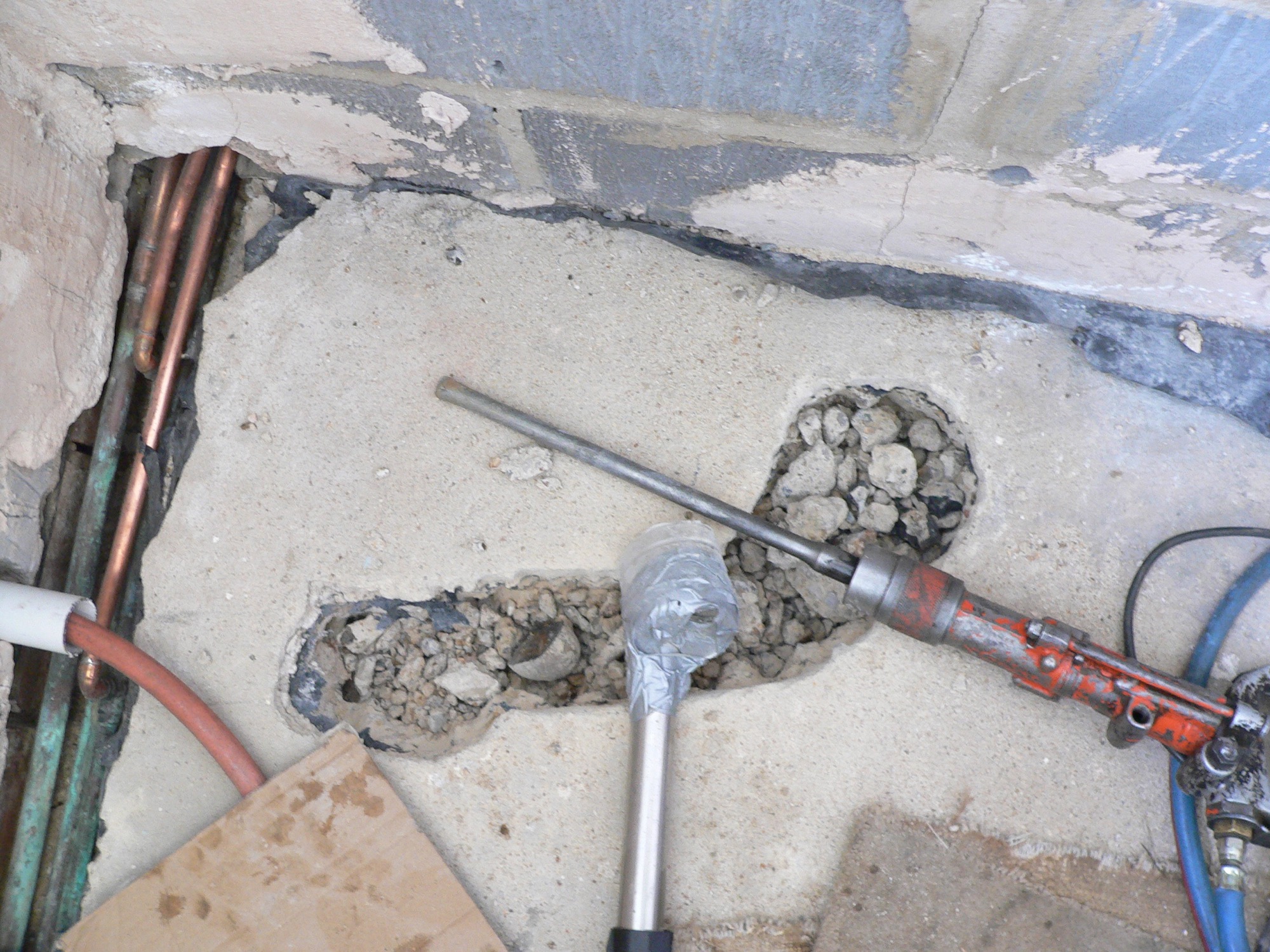
February 18, 2025 at 6:46 pm #43404ParticipantMany thanks to everyone for sharing their knowledge and experiences. I have now pretty well conceded that my flywheel assy is permanently seized onto the taper. I even resorted to cutting away the outer of the wheel to give me access for heat, and hopefully the contact points. For the next move, I have ordered an Ebay flywheel – not knowing if it is the right one, as mine has no serial No. on it with a view to detaching my brass wheel from its hub, and fitting the “new” one.
The logic is that there must be some sort of flywheel to give inertia for running the engine, but more importantly, the flywheel carries the fan and the wheel for the pull-start. Having restored some sort of flywheel, then I plan to fit some sort of external magneto. The timing of the contact breaker should be OK as this relates to the cam on the seized flywheel shaft. One possibility is to make a circuit with an old fashioned ignition coil, as on cars of yesteryear,
wit a rechargeable battery and capacitor, using only the Villiers contact points to time the spark.Idon’t think the MECO unit can be used because my “replacement” flywheel may not have the magnet in the right place, and I don’t have much access to the coil . My next task is to find a small reasonably priced 12V rechargeable battery. I live in France and stuff the comes from UK can incur customs duty as well as hefty carriage costs.
Wish me luck……… DaveFebruary 19, 2025 at 8:12 am #43405 charlieKeymaster
Dave, the flywheel also contains the permanent magnets for the magneto.
February 19, 2025 at 3:40 pm #43412sidevalve5ParticipantHi Dave,
Personally I would do the easy and/or cheap options first. If the multimeter tests are within the range indicated and the points are clean and correctly adjusted. But there is still no, or just a very weak spark. Suspect the condenser and as you say, you can fit one externally. Only fit new, not second hand or NOS. Would enquire at Villersparts if their square type is a modern capacitor and if so get one, or one from Brightsparks, or a 630v 220nF / 0.22uF capacitor locally. If the coil appears OK, but access to the points is so poor you cannot do the degree of work required to get them in good condition. Would fit an externally mounted Meco or Nova ignition unit. Angus Shapland (aka wristpin) has fitted lots on Villiers Mk25c’s and speaks highly of them. It appears the only problem with them is the voltage induced by the flux reversal has to be high enough to trigger the module. It is suggested 3v is needed, so the flywheel needs a bit of a spin. If the primary coil is poor, or there is a short in the circuit, then this may not be enough.
If the coil is duff, then things get a lot more difficult. You could as you say, make up a total loss Kettering ignition system and leave the points in place. However, I would firstly check the timing which should be 5/32” BTDC. If someone was so hamfisted as to overtighten the captive nut, I would not trust them to get the timing correct either. Would be great if you could get the screws undo that hold the brass flywheel onto the hub. But if you could do that, I am presuming you could access the coil and points sufficiently to remove them if required. Then am not sure if fitting the flywheel you have got from ebay will be of any benefit. Other than because you have damaged beyond repair the original when you removed it. If you are still going for the total loss ignition system, then if the magnet is in the incorrect position on the flywheel, it will make no difference. Would be surprised if the magnet was not aligned with the points cam lobe anyway. When the magnet passes over the soft core of the coil and flux reversal occurs, the voltage to the primary jumps. It is at that instant the points open, current ceases to flow through the primary (a good condenser is needed), the resulting collapse of the magnetic field induces very high voltage in the secondary which seeks a route to ground. So the lobe on the flywheel has to be synchronized to the position of the magnet on the rim. As the Mk25c does not have a keyway, you can adjust the timing. A problem that could occur in swapping the flywheels of different models could be the difference in magnet length and cam lobe profile.
If import duties and carriage from the UK are prohibitive. You could always try the single wire energy transfer system I posted on the 9th February. You will still need the 6v motorcycle coil for the Kettering system. The only extra would be 100g of 22swg enamelled wire and the time it would take to strip and then rewind the coil. For the total loss system you will need a battery and the time it takes to make a mounting for it. The coil, wire or battery could all be sourced in France. Am thinking of making a bit of test equipment with the battery I use in a cordless drill and fitting a potentiometer to regulate the voltage.
Lots of choices, but think you have settled on a course of action. Wish you the best of luck and keep us posted to how you get on.
Grahame
February 19, 2025 at 8:24 pm #43418ParticipantI’m still a little confused here , going back to your very first photo , it looks to me like you have(or had) the flywheel removed , it appears to be in your hand , and certainly not siezed on the crank ????
Andy.
-
AuthorPosts
- You must be logged in to reply to this topic.