Forum Replies Created
-
AuthorPosts
-
November 30, 2019 at 12:33 pm #32764
 trusty220Keymaster
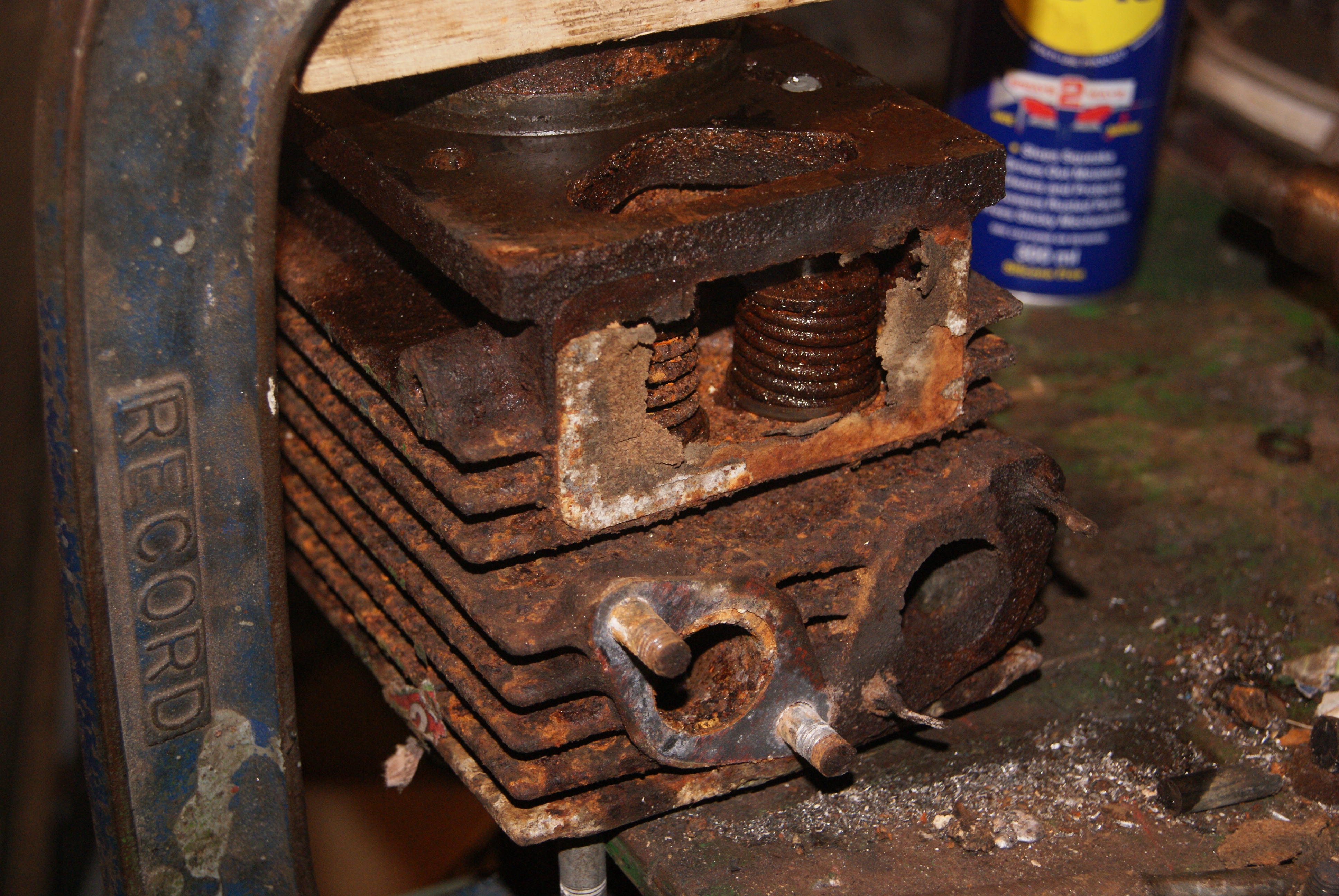
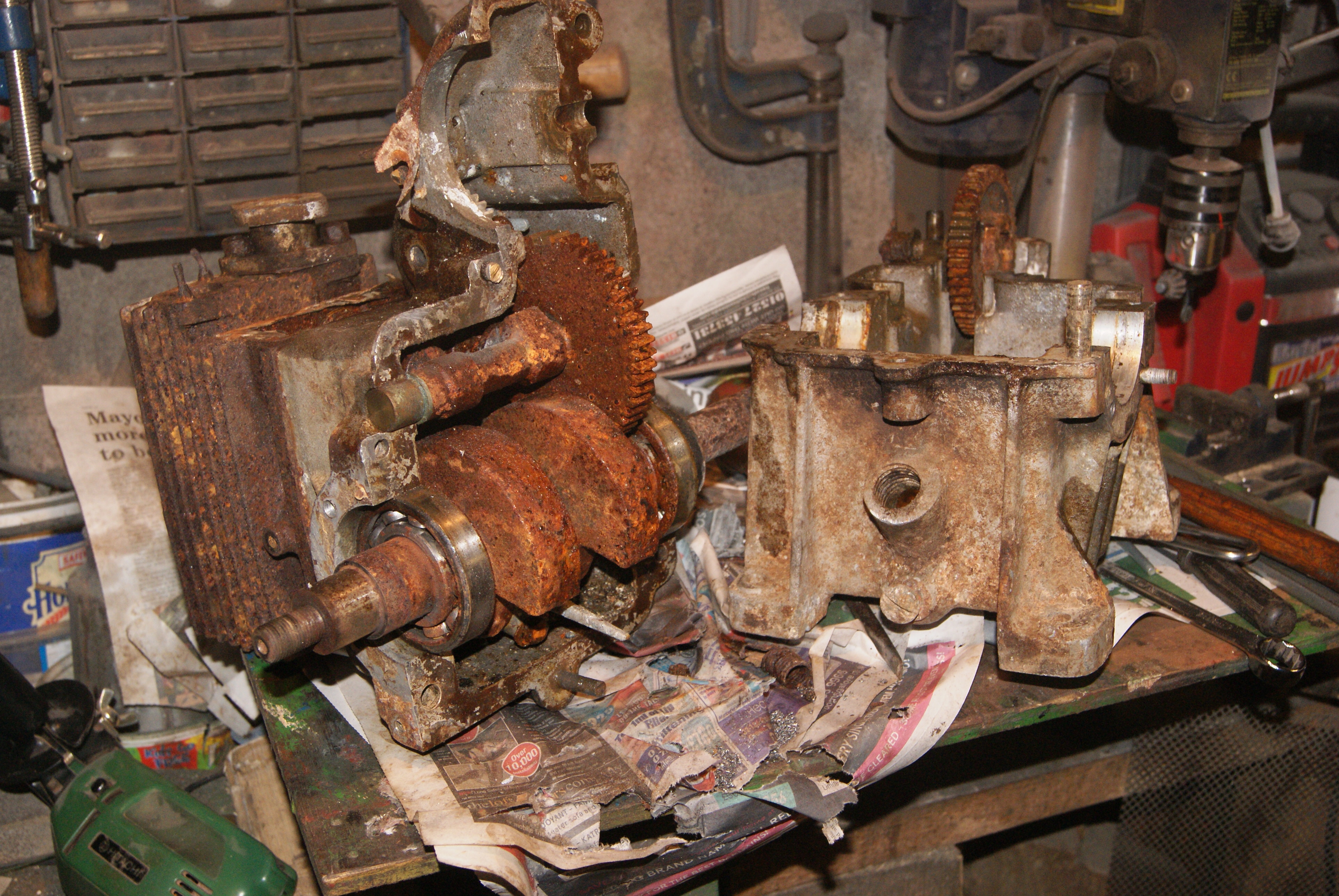
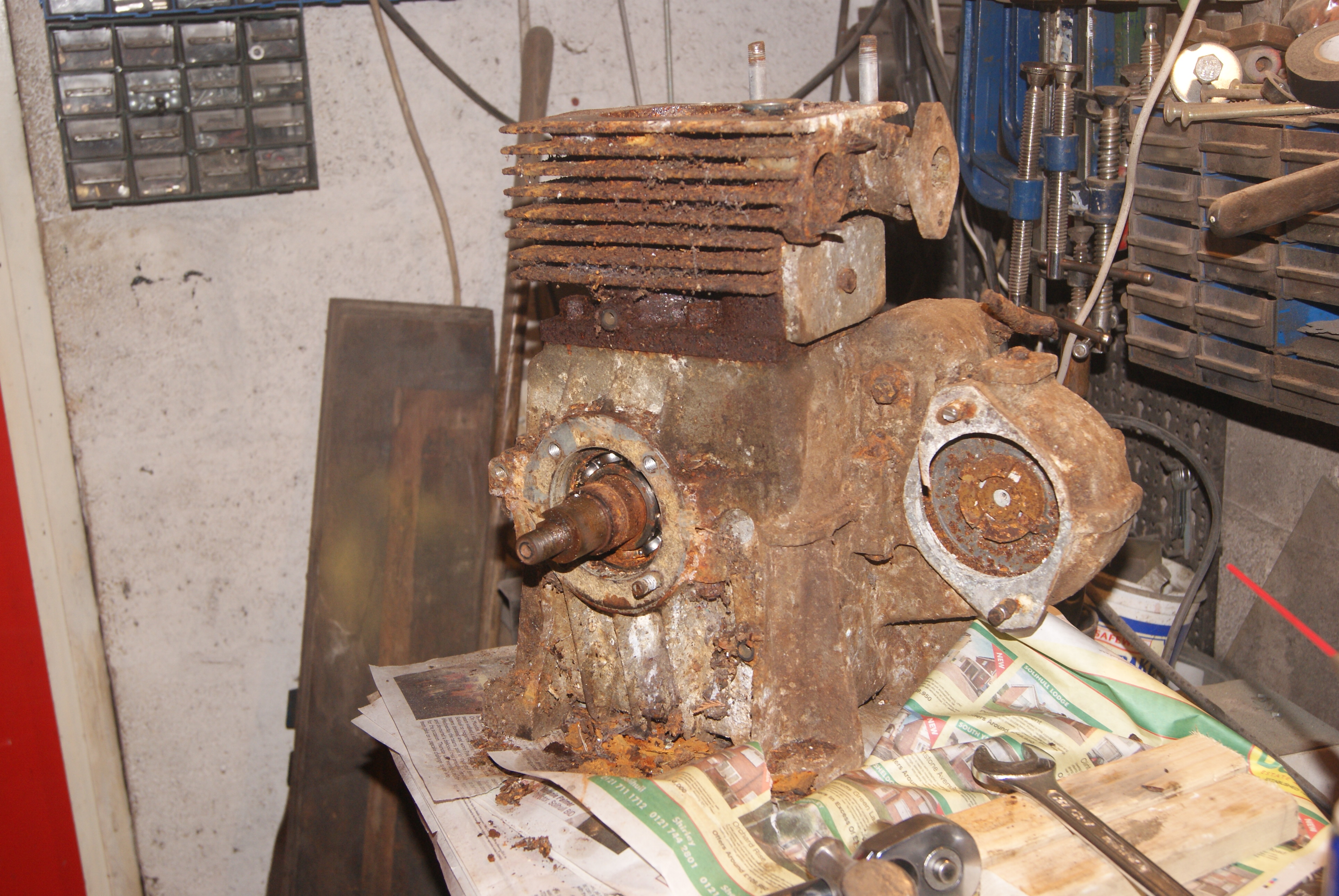
I’ve now got as far as I can get with it. The crankshaft is out, the big end is off, camshaft out and the barrel removed from the crankcase. One thing that I can’t seem to do at the moment is to unstick the piston from the bore as it’s corroded itself together. I don’t want to damage either and so excess force is out of the question, at least for now until I’ve tried everything else.
The next part of the process will be to boil the assembly in oil in an effort to free the piston; usually I would put the whole lot in acid but the piston is aluminium and won’t survive that process! The crankshaft, camshaft and magneto drive gears are all made of steel and are being acid stripped as we speak, so they should look half decent shortly.
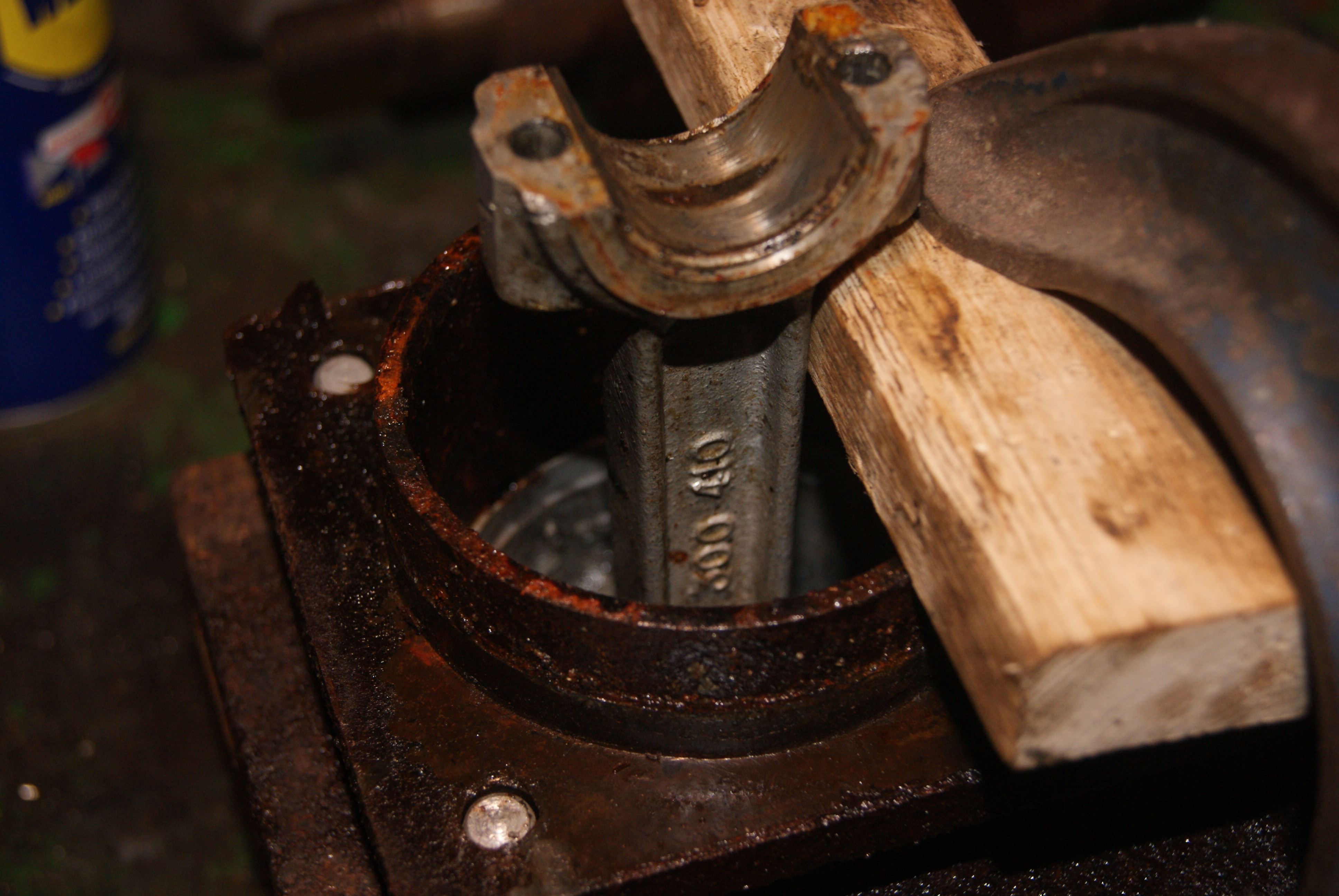
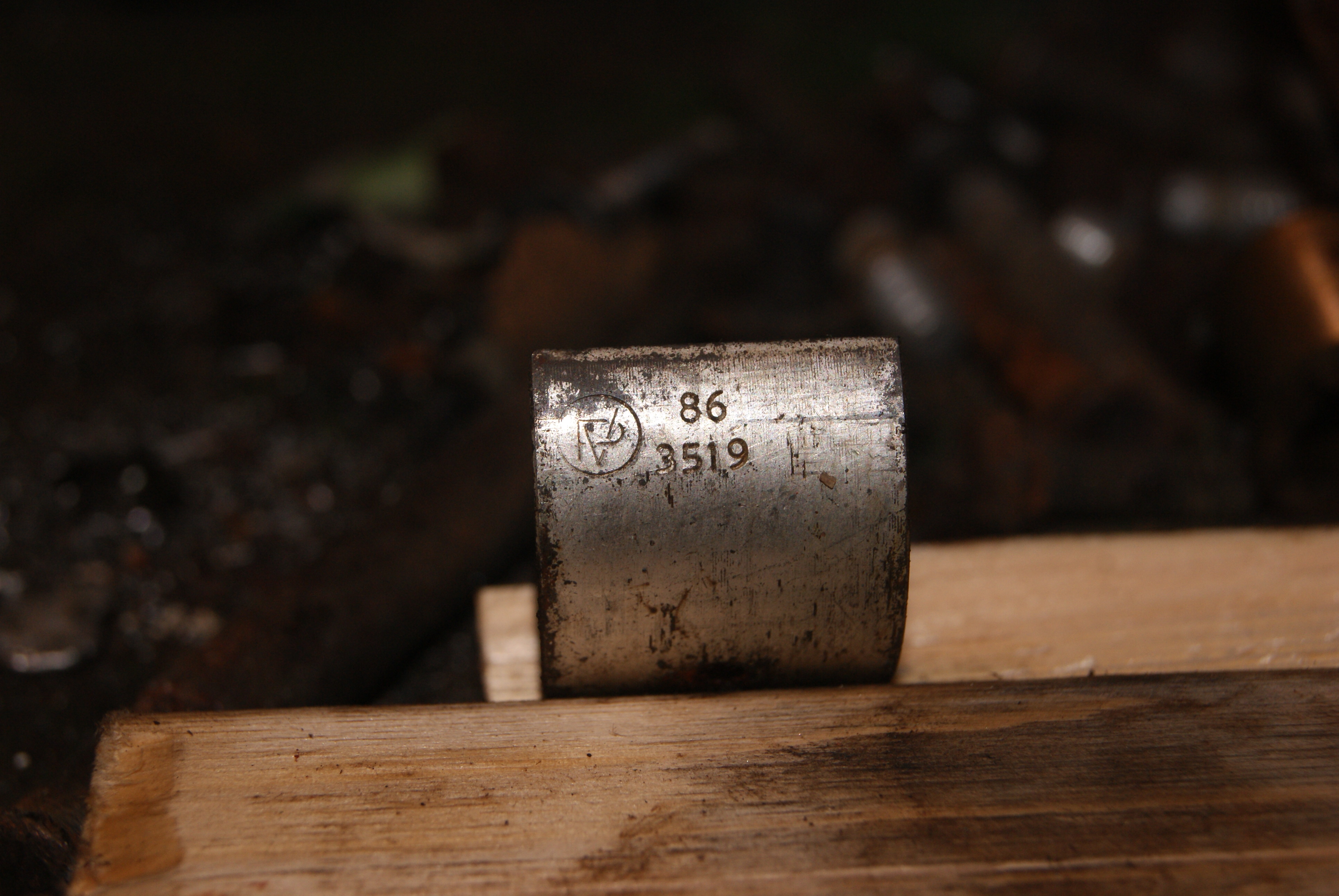
The connecting rod has some numbers cast into it and the crankshaft has also got some numbers and a logo stamped onto the surface. I’ve tried to take photo’s of both, but hopefully the crankshaft numbers will be more legible without the rust.
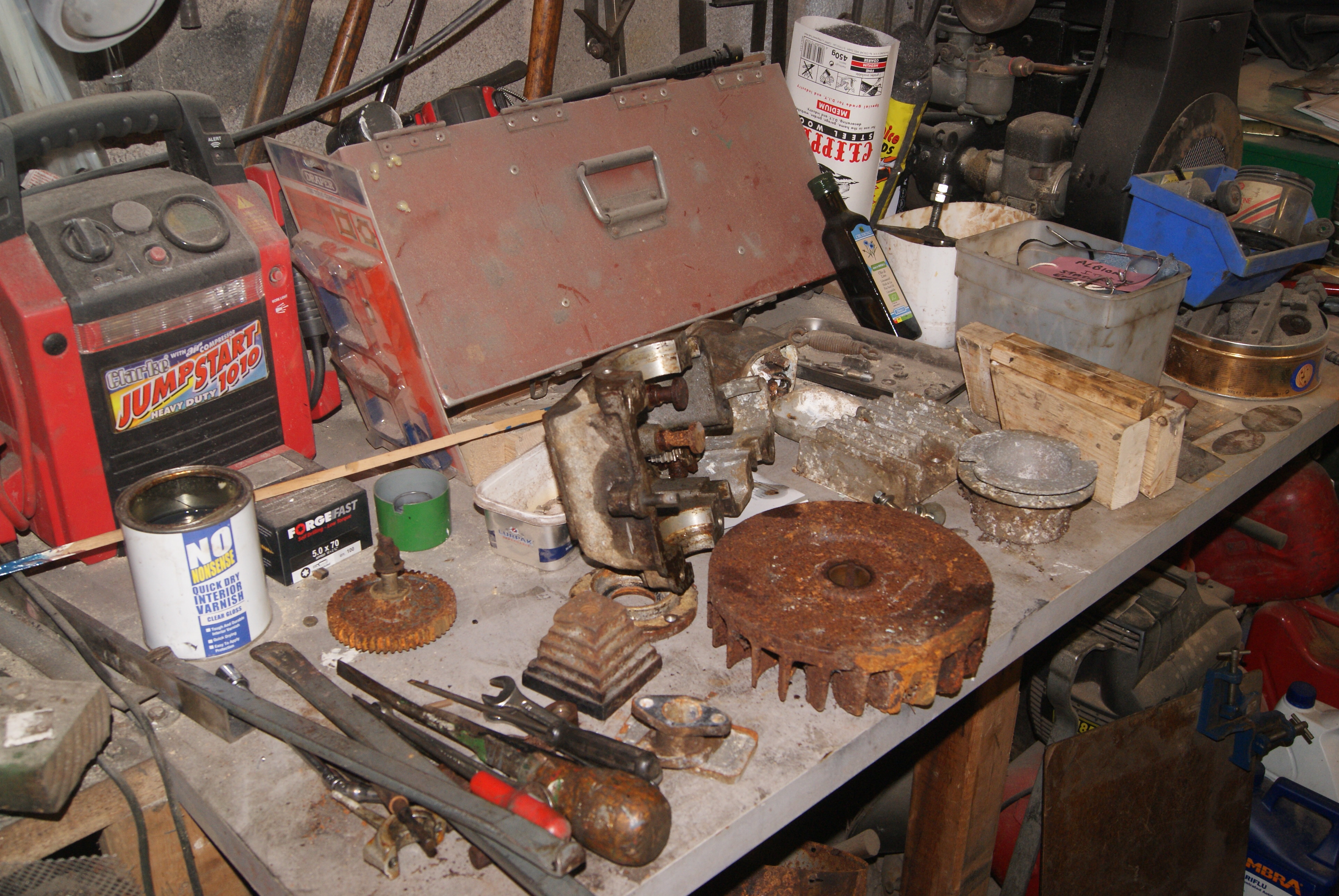
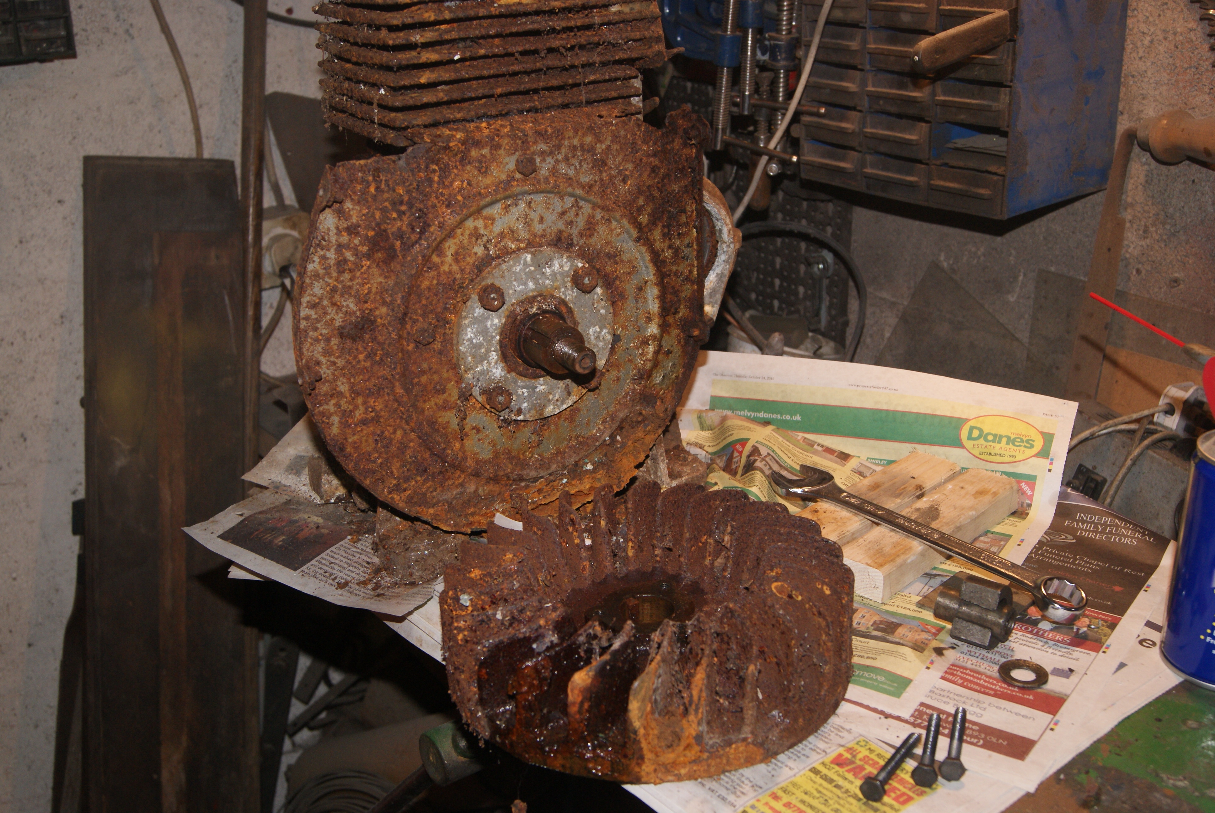
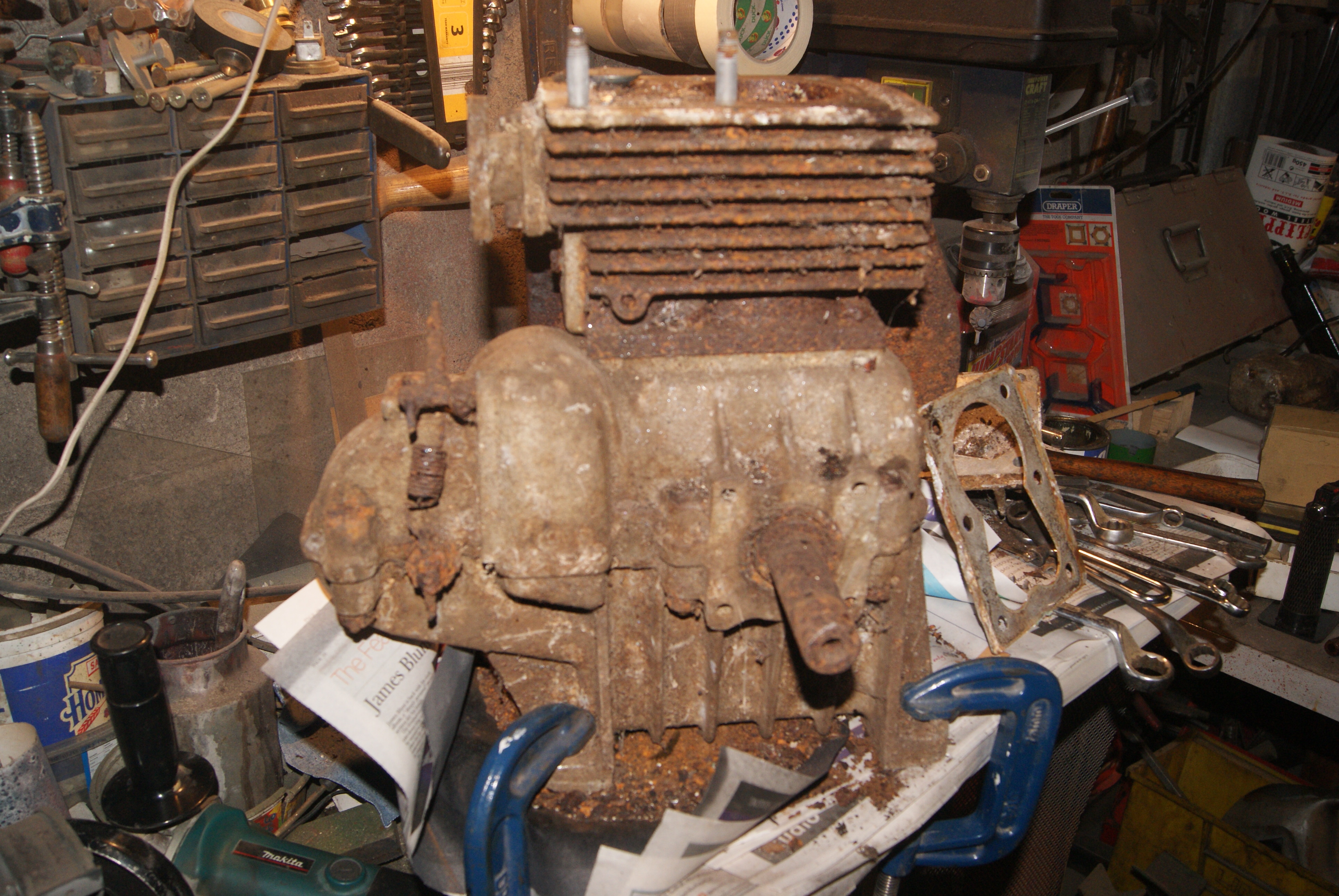
I’ve taken a photo of a very messy workbench for you, Angus! You can see that I’ve not had time to have a tidy up whilst dragging this lump apart, but I can assure you that all is now spick and span and waiting for the next stage which will be the boiling oil.
Now, where’s Mrs. Geoff? Do you think she’ll miss this big saucepan……?
Attachments:
November 29, 2019 at 7:49 am #32763trusty220KeymasterIn the background is a drill press and my Clarke compressor/jump start pack behind that. Unless you’re referring to an earlier photo with the Tecumseh ignition tester in a purpose-made case?
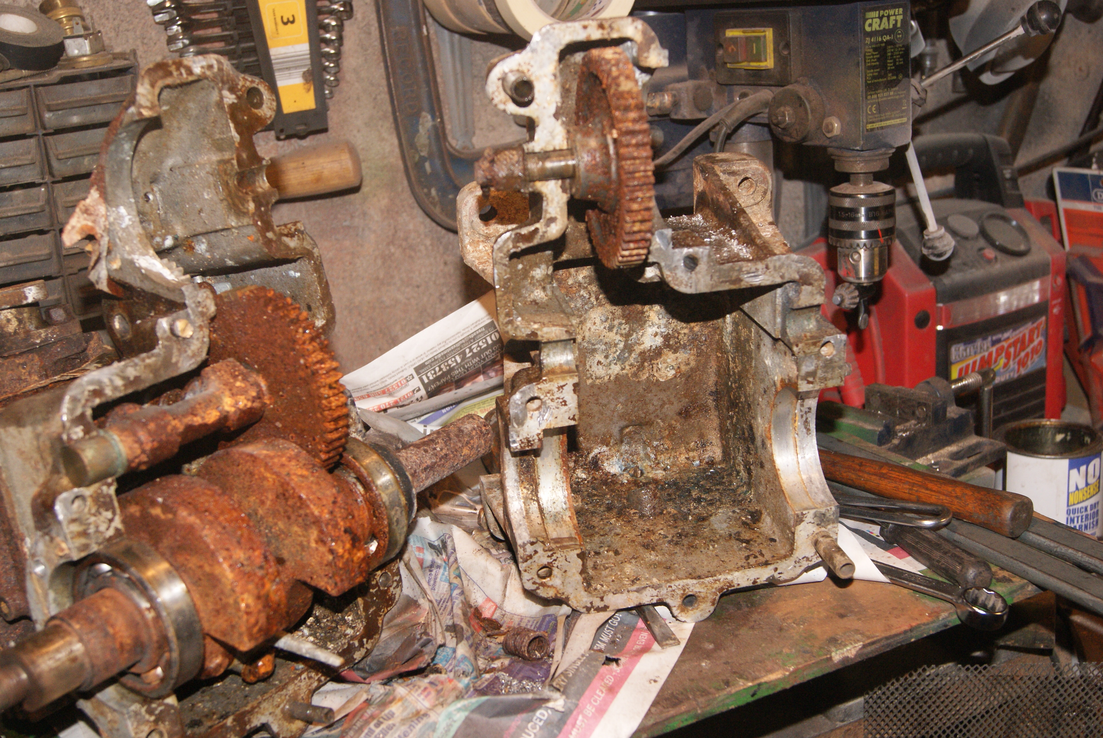
Not home and dry yet, but much closer. I’m not too concerned about the surface rust on the crankshaft and camshaft gears. It can make things look much worse than they are, but the main concern will be the state of the big-end bearing surface. This weekend will be interesting!
I don’t suppose anybody reading this can identify any single part of this engine. I think it’s a one-off, probably hand built but using certain items off-the-shelf to speed up the build. That’s why I thought it looked similar to a Villiers because the cowlings seemed to follow their design, and they may well have been “borrowed” to fill a need, but very little else on this engine would suggest Villiers to me. The use of left-handed threads would suggest an engineer’s input because production would try to make the engine as simple and cheaply as possible; I forgot to mention that the governor shaft is located with a left-handed 5/16″ bolt as well as the flywheel nut.
November 28, 2019 at 9:44 pm #32754trusty220KeymasterThis engine definitely isn’t giving up it’s secrets easily. I’ve spent hours tonight trying to get the two halves of the crankcase apart and finally succeeded. The problem is that all of the bolts are badly wasted away and are in such inaccessible positions that you can’t get any tools near them to remove them. In the end I had to resort to grinding part of each one’s nut away so that I could split the nut and gently tap the bolt out of it’s hole. That worked for four of them, but there are six in all and I had to drill one bolt out and chop the other one piecemeal.
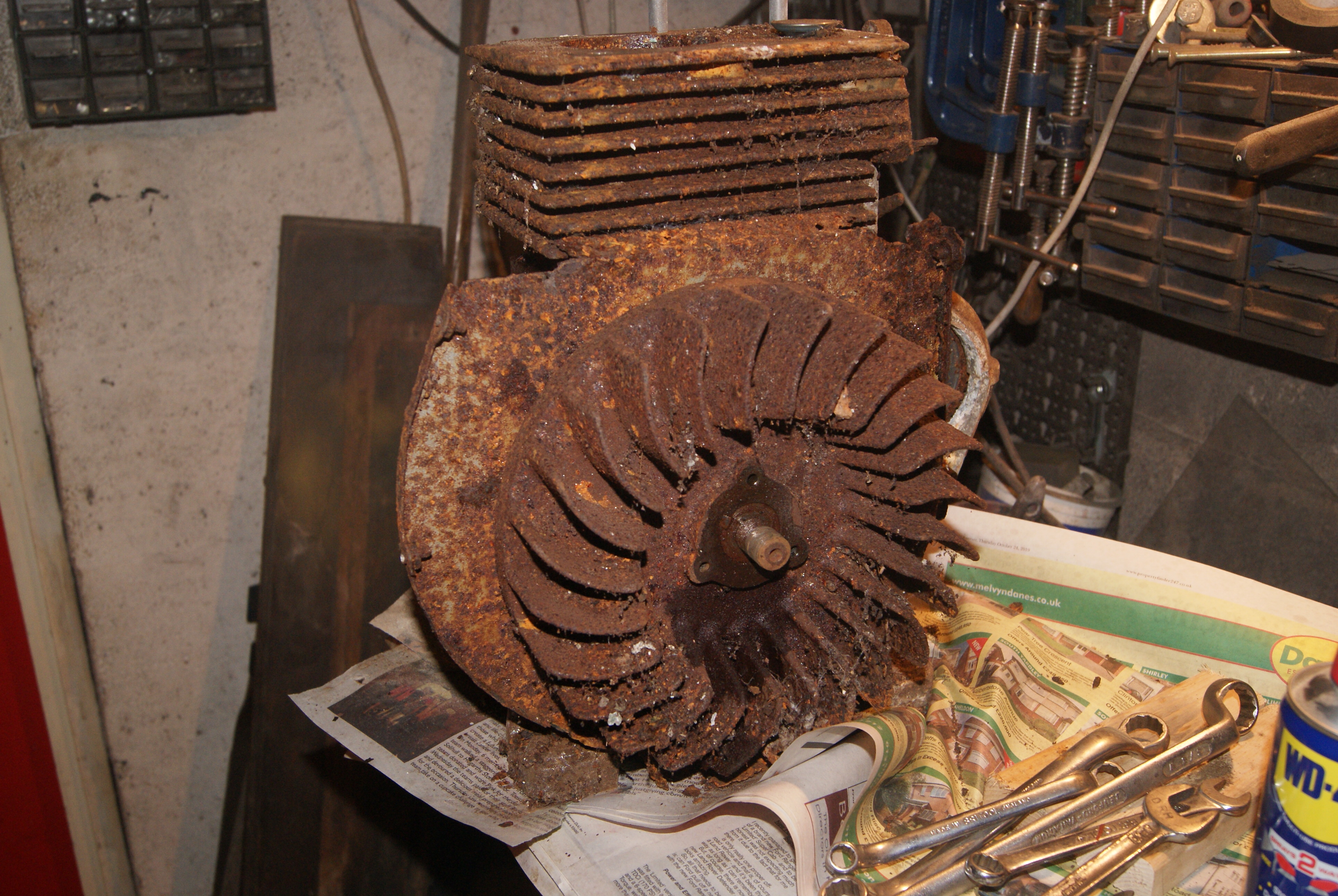
I was asked today what was on the reverse side of the flywheel- nothing, but here’s the photo.
Attachments:
November 28, 2019 at 3:39 pm #32753trusty220KeymasterNot a bad idea, Charlie. I’ll wait until I’ve dismantled it completely first before I start to put pen to paper.
I’ve treated it to a steam clean at work today so tonight’s effort won’t be quite so difficult (I hope). I’m starting to wish that I’d left the muck on now!
November 27, 2019 at 7:16 pm #32745trusty220KeymasterHere are tonight’s pictures. It’s turning into quite a saga, isn’t it?
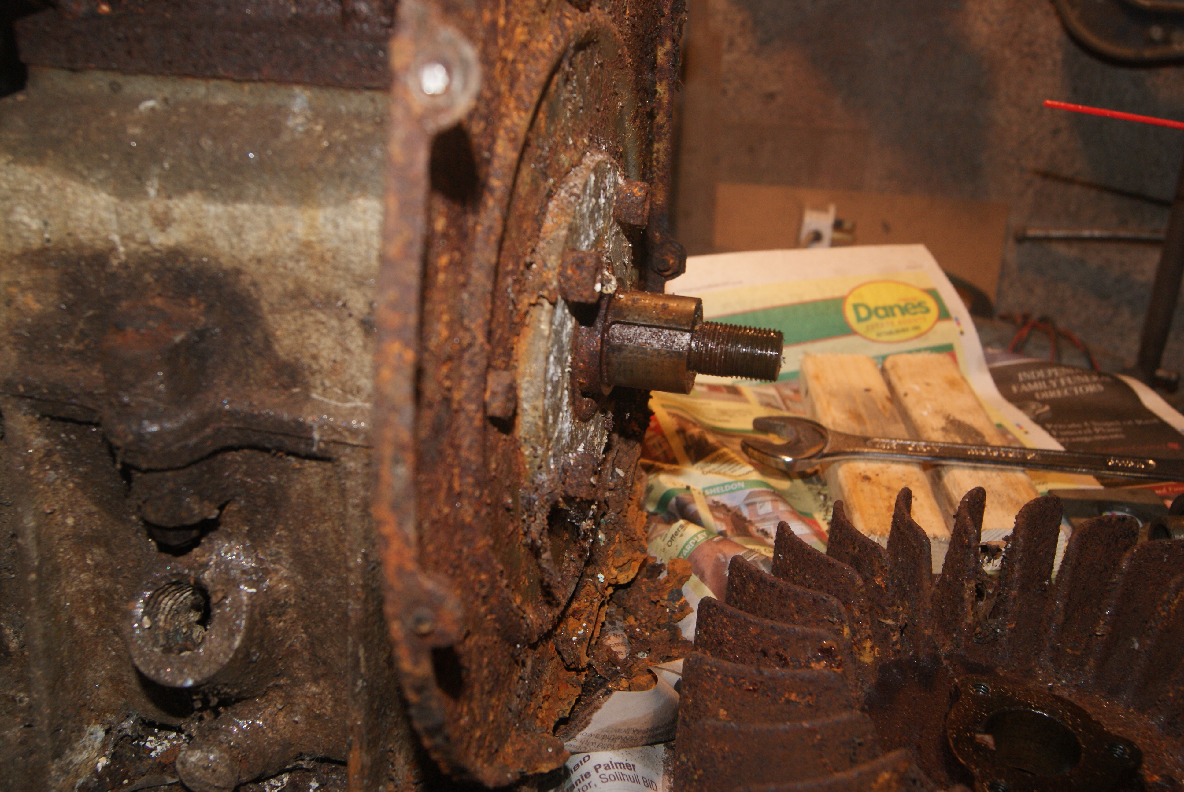
To recap, I made a puller to tension the flywheel and was intending to heat it whilst under tension. After I put a tension on the puller I thought that I’d tap the puller with a copper mallet and to my surprise the puller became loose. I kept turning and the flywheel kept coming- it’s not on a taper as in usual practice but is on a parallel shaft with a steel key, all held together with a large nut on a left-handed thread.
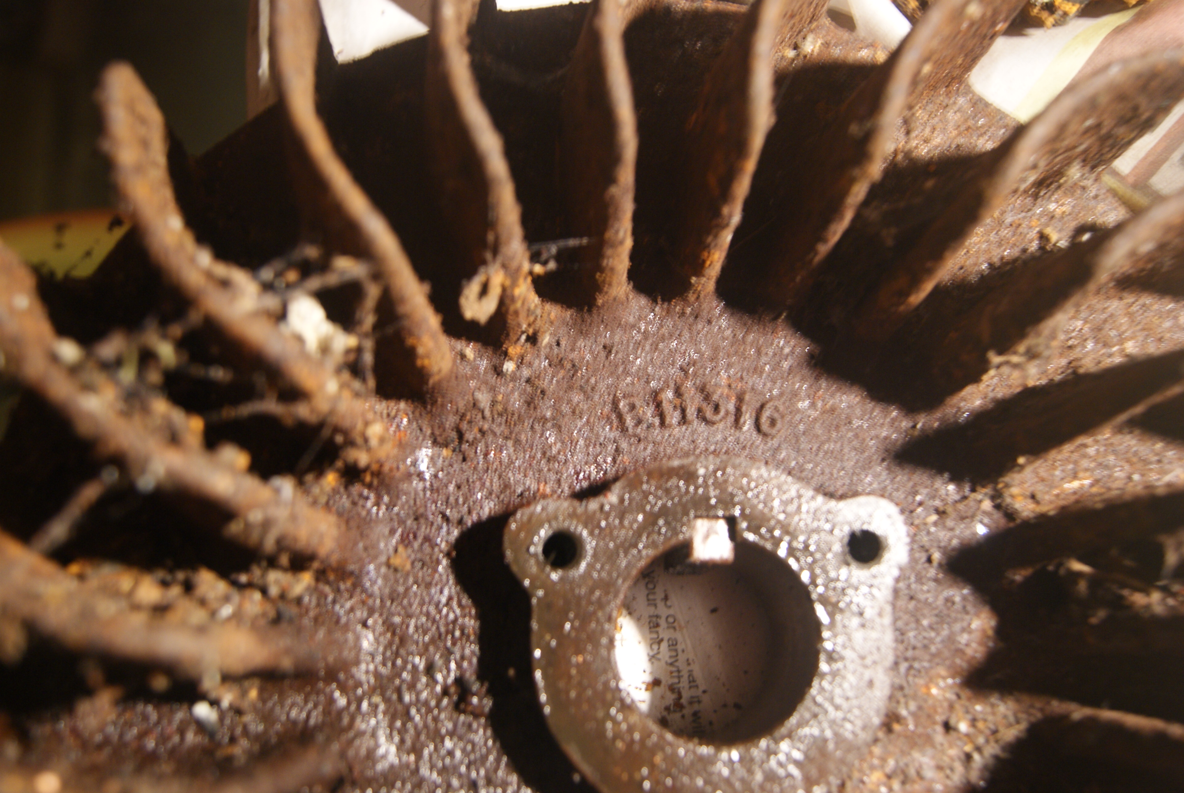
The flywheel does have a number cast into it, but it’s probably an “off-the-shelf” item that has been modified to fit this engine.
Once the flywheel was off it gave access to three screws that held the rear half of the cowling on. After removing this, four nuts came off easily and the main bearing/oil seal carrier was taken off to reveal a ball race behind.
I’ve left the rest for another night and filled the bore with WD40 to soak through and hopefully free the piston.
Have a look at the latest photo’s.
Attachments:
November 26, 2019 at 9:41 pm #32743trusty220KeymasterI’m starting to think the same myself. It does have one or two features that a mass produced engine wouldn’t have, but until I’m sure I will keep digging away at it in the hope that the conrod, piston or crankshaft will have some identification mark.
You may even see it on a Trusty yet, Andy!
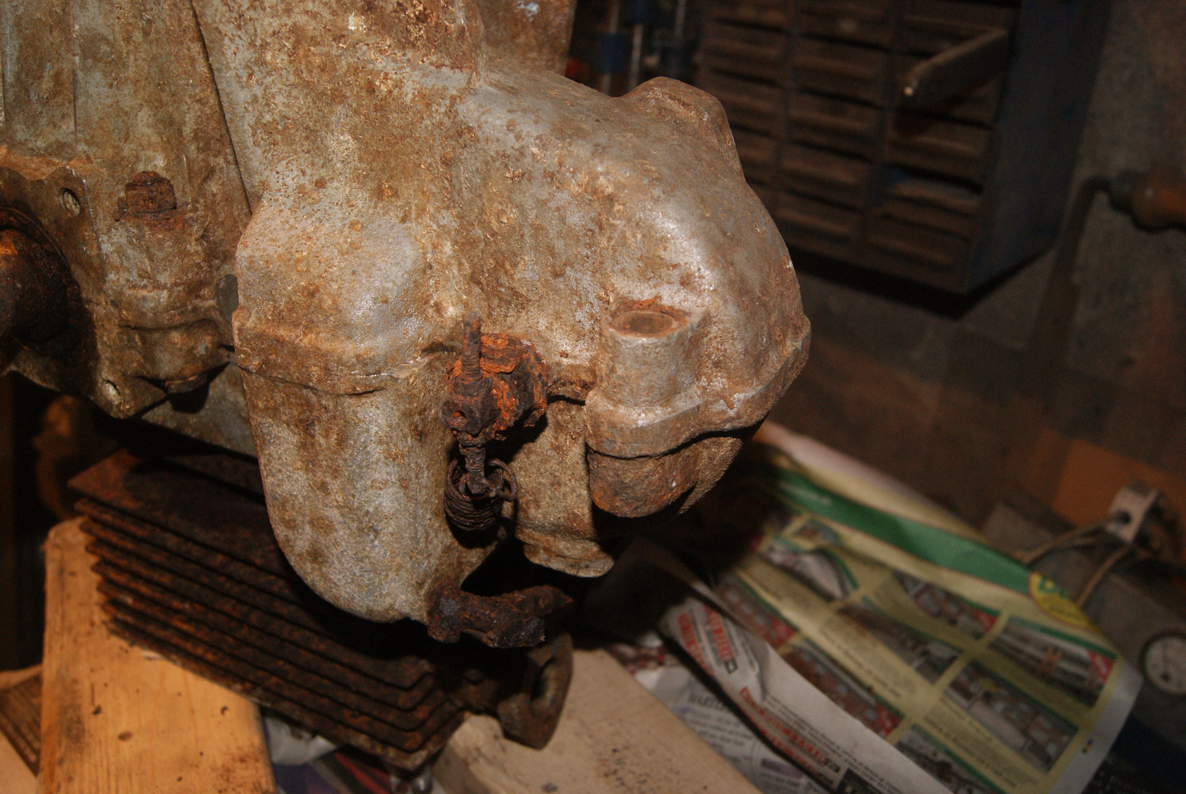
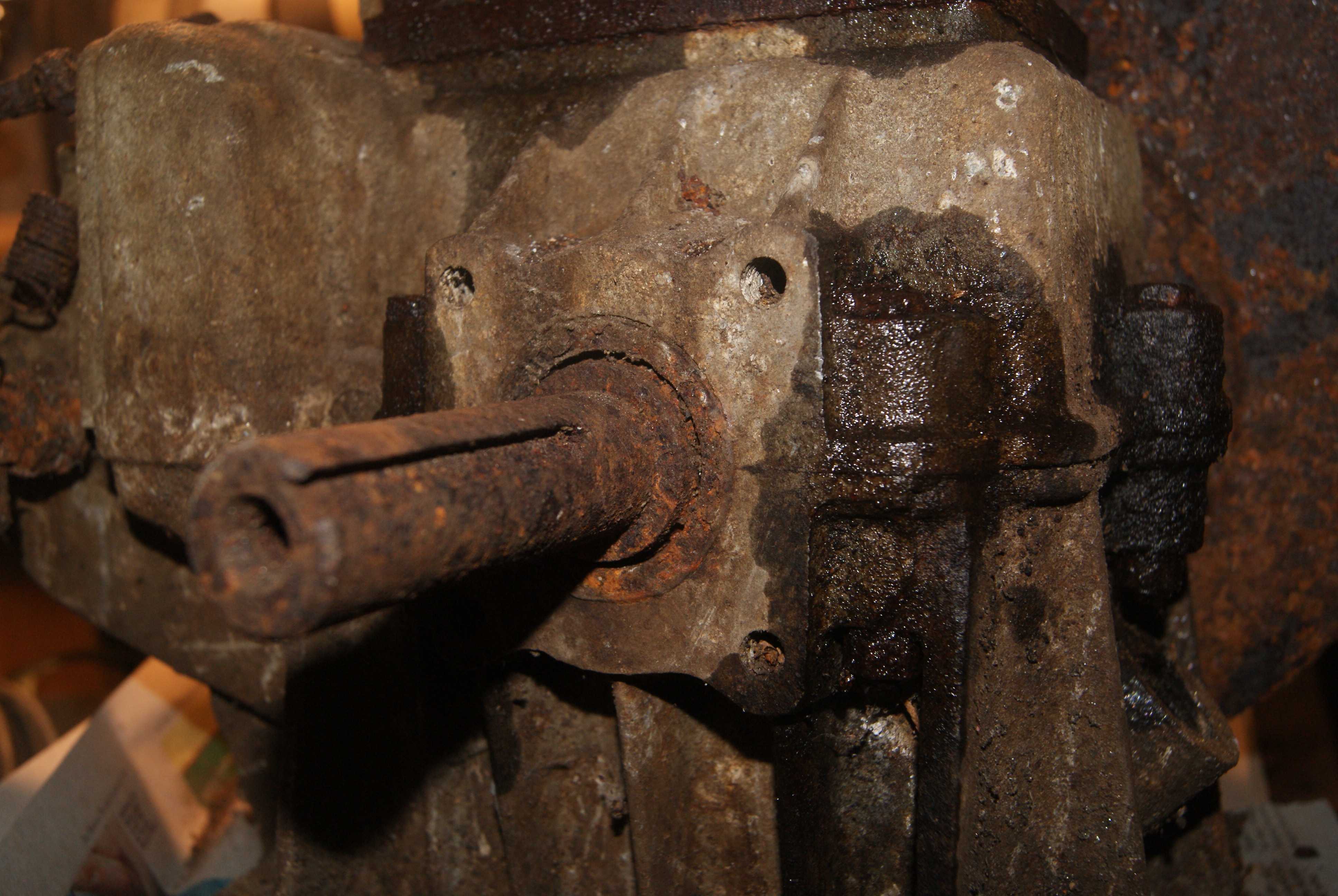
November 26, 2019 at 6:15 pm #32736trusty220KeymasterA few more clues tonight. The flywheel nut is left-handed and fitted with a locking tab- have a look at the photo. I can’t shift the flywheel by all of the short-cut methods, so I’m going to have to make a puller to get it off.
Until the flywheel is off I can’t separate the crankcase halves. The split is through the main bearings and the halves are secured with bolts and nuts. At first I thought they were studs with nuts on, but scraping away the rust and dirt revealed bolt heads at the top which go through to the bottom half where they are nutted up. Very unusual.
Any ideas yet?
Attachments:
November 26, 2019 at 7:48 am #32734trusty220KeymasterA good point. It’s so easy to overlook the obvious when you’re trying to find that elusive clue!
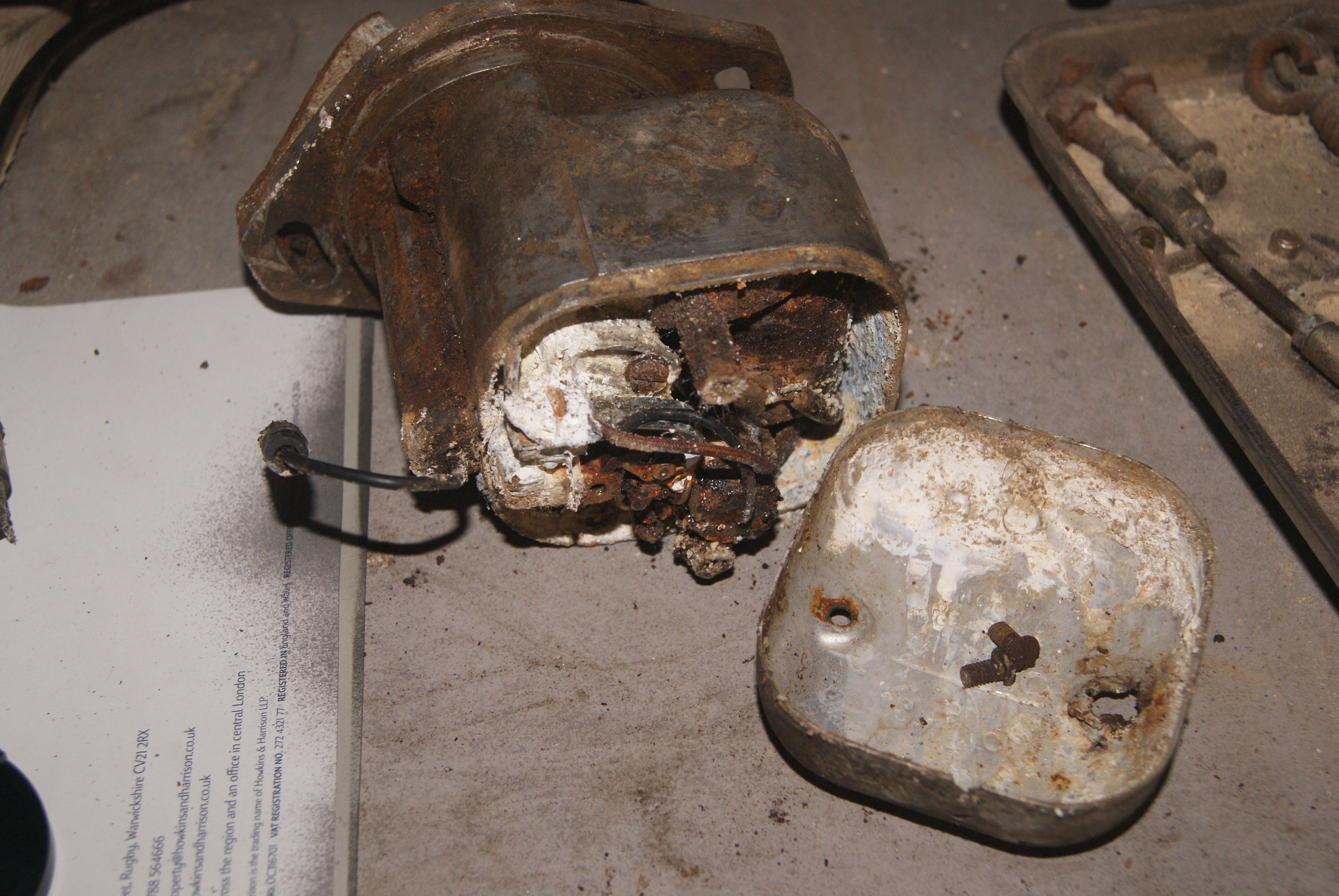
Such a shame that it hasn’t been stored in a dry place. Everything is corroded and wasted away; even the magneto cap screws didn’t give in without a fight, then when I got the cap off it was full of white powder. At least it shouldn’t be too difficult to replace the mag and it won’t affect the originality of the engine.
November 24, 2019 at 6:12 pm #32731trusty220KeymasterI reckon it’s of British origin. The head studs are 3/8″ Whitworth (16 threads per inch) at the bottom where they screw into the barrel and 3/8″ BSF (20 threads per inch) at the top where the head nuts screw on.
I can’t find any identification on the Wipac CJ magneto, although the master parts listing that I have lists JAP and Petter as the only two makes that use the CJ.
I think I’ll have to dig a little deeper and see what’s inside the crankcase.
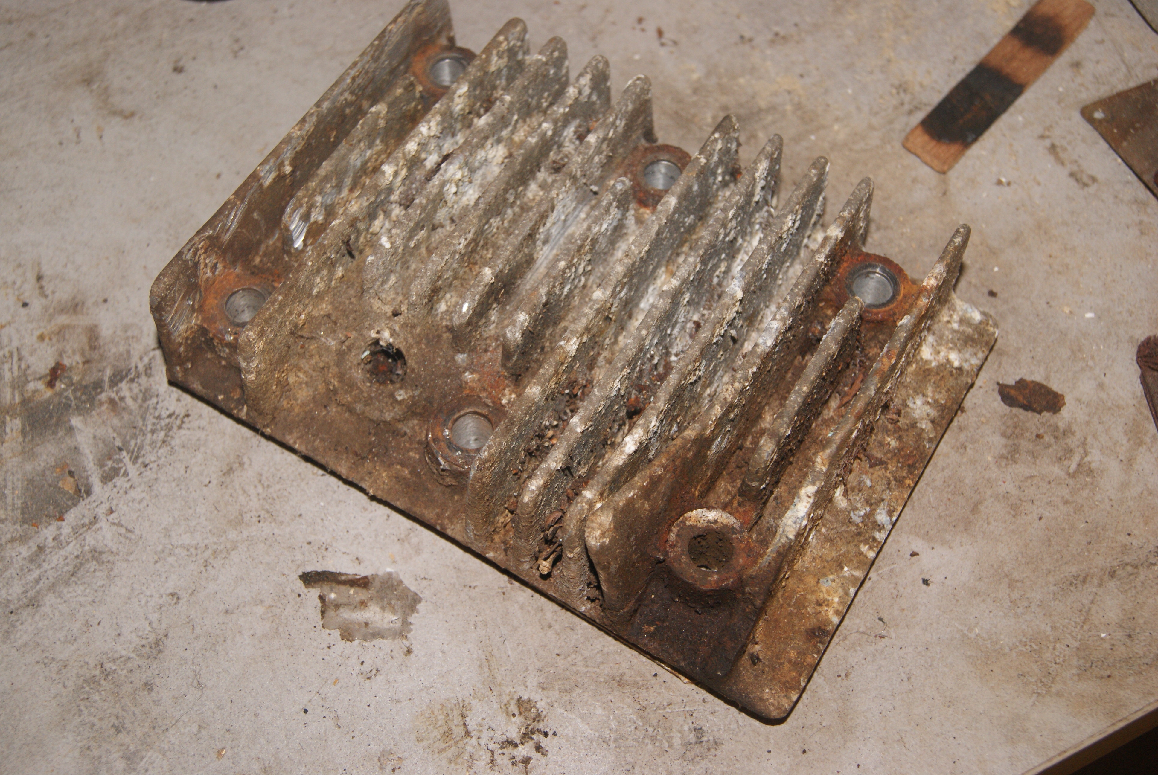
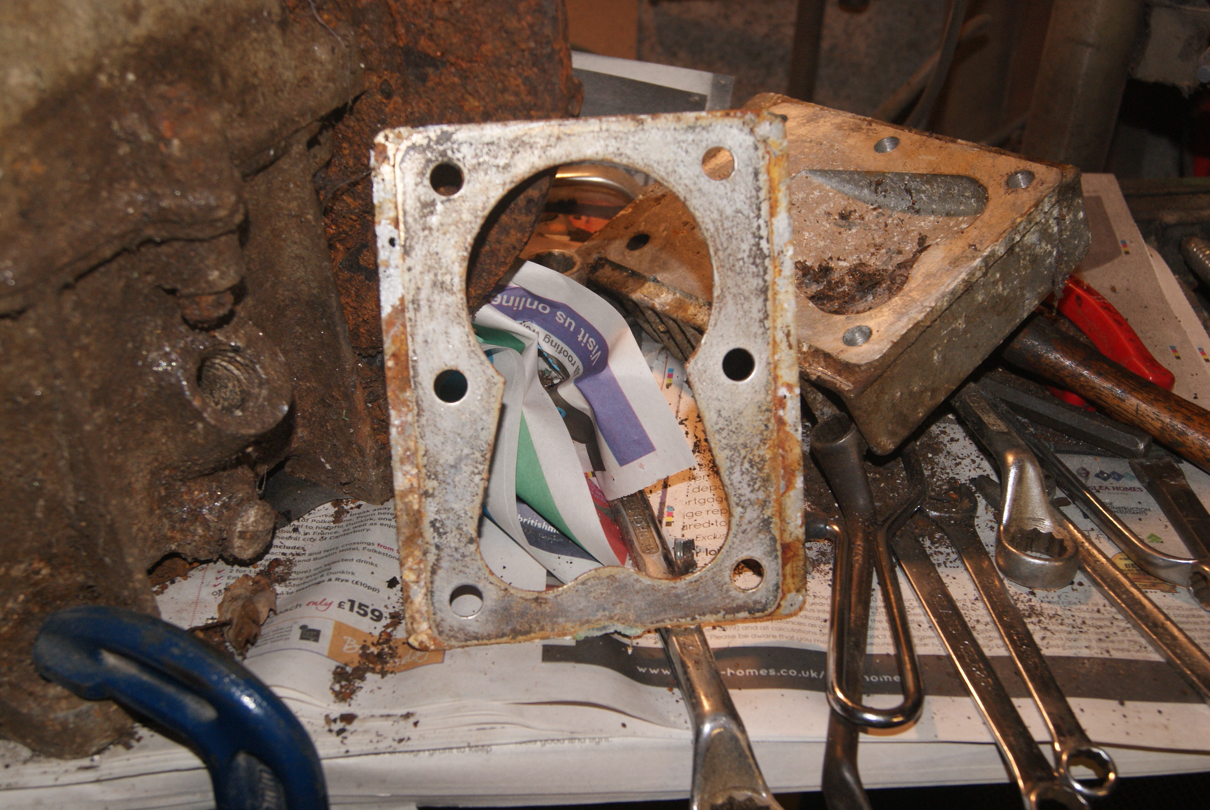
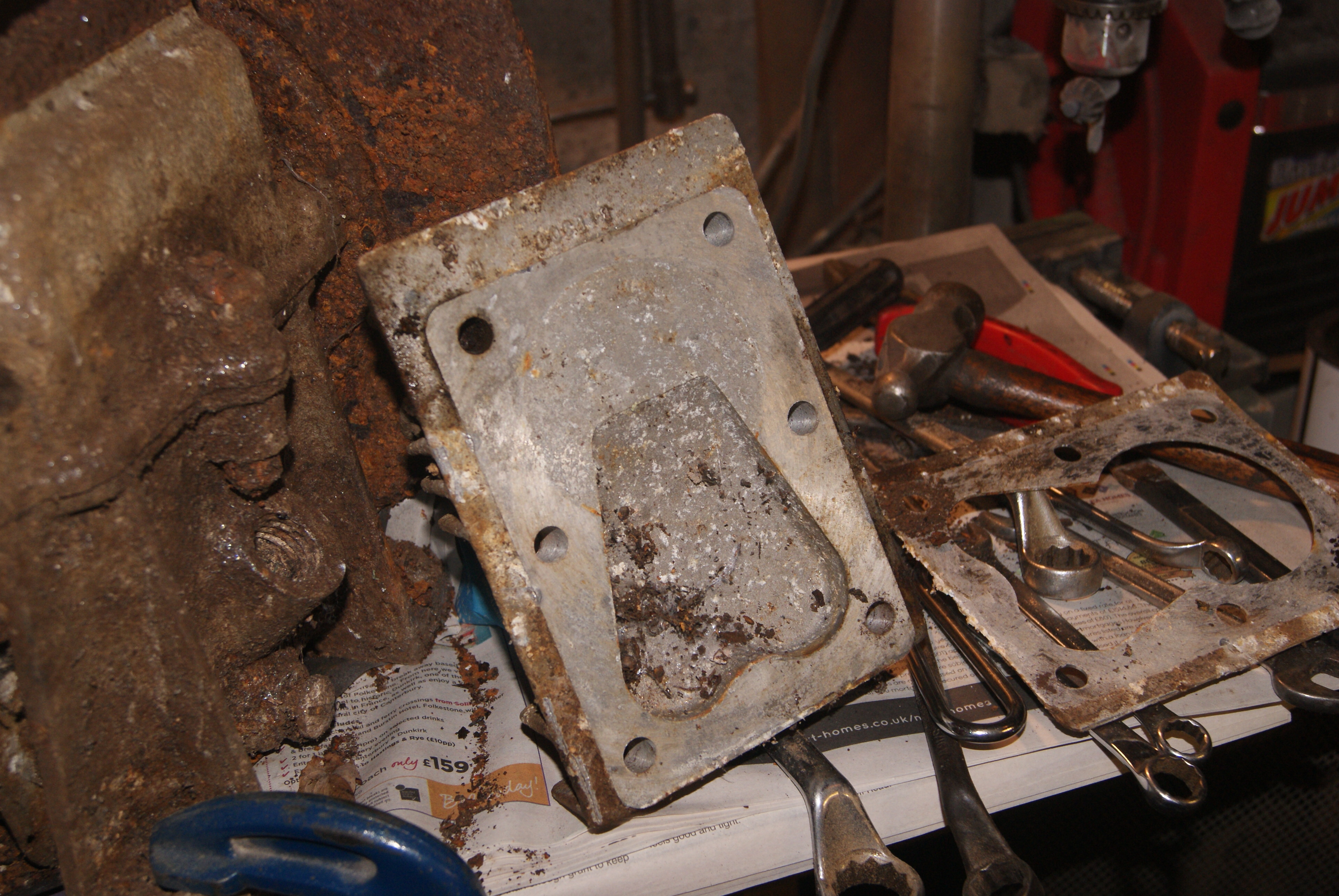
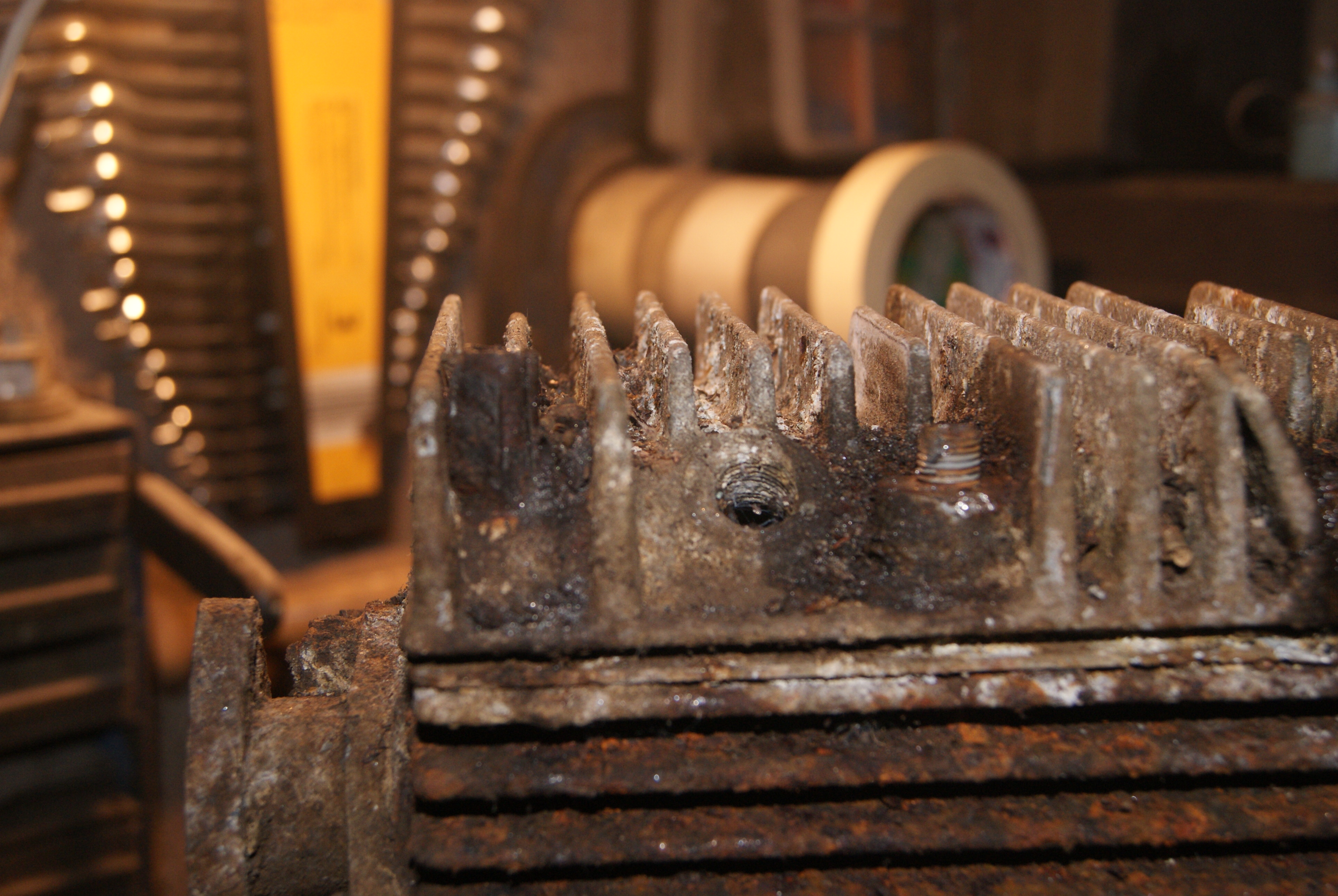
November 24, 2019 at 2:54 pm #32724trusty220KeymasterStill no idea yet, but the head gasket looks very much a like a one-off. See for yourself on the photo’s, and the head bolts don’t follow normal practice either with only six of them. Two holes for the head bolts are very close to a cooling fin which makes it impossible to put a socket onto. All of the bolt heads are severely wasted away and I’ve had to cut most of them off to get anywhere with it, otherwise I’d have some idea if they are metric, AF or Whitworth sizes.
I suppose I’m just going to have to measure the threads and do the job properly!
Attachments:
November 24, 2019 at 11:49 am #32723trusty220KeymasterIt makes me feel better now; I thought somebody was going to reply and say that it was definitely a so-and-so! I think I’ll keep exploring and take some of the cowlings off and give it a clean up to see if it reveals anything.
Another avenue may be the magneto type if I can find a plate on it, then look up the applications.
Keep trying!
November 21, 2019 at 3:57 pm #32691trusty220KeymasterThe tuning of the carburettor has to be done in sequence and somebody that isn’t used to these carbs may not appreciate that.
Firstly you want to screw in the main jet until you feel it stop, then turn it out one turn. Do the same with the slow-running air screw on the side of the barrel. That should be sufficient to get it running.
When it’s running, set the throttle on a fast idle (around 1500 revs) so that the majority of the fuel that the engine’s running on is going through the main jet. Then wind the main jet out until the engine starts to run rough; turn it back in again until it runs rough again, then turn it out half the distance between these limits. This should then be the ideal setting for the main jet.
For tick-over you want to close the throttle and repeat the process with the airscrew on the side of the barrel, adjusting the slow-running screw on the throttle spindle to achieve a sensible tick-over speed.
Best of luck- as Charlie says, if the choke is opening and closing by itself you really want to stop it. It’s not like a car choke, it is purely a cold-starting aid to richen the mixture and the engine will not run with the choke on when it’s warm.
November 14, 2019 at 2:35 pm #32655trusty220KeymasterWe use an ultrasonic cleaner in our workshop but we find that it isn’t foolproof. By all means use it but more often than not we find that we have to clean the carbs the old fashioned way with plenty of clean petrol on hand, an airline and even a small piece of soft fuse wire to poke the holes out in extreme cases.
Don’t think I’m advising you to poke wire into the holes because that’s the easiest way to enlarge them, then it won’t work at all! Better to try all other methods and if all else fails try a piece of wire, but make sure it’s small diameter soft wire that won’t affect the hole size. Certainly don’t use gas nozzle reamers like I’ve seen someone do years ago- the carb was scrap after he’d “cleaned” it!
You may want to have a look at the section that I did on rebuilding a Norton Big Four engine on a Trusty Steed. There are some pictures on there of the carburettor which you may find useful.
Best of luck with it, it sounds like you’re nearly there.
November 14, 2019 at 9:09 am #32653trusty220KeymasterI’ve found that these carbs do block up readily, probably because they have so many fine drillings in so many different places it doesn’t take much in the way of debris to start a blockage.
Trouble spots are usually confined to the brass main jet and holder which needs to be removed and thoroughly cleaned, including the cross-drillings in the holder, and also the slow-running jets which are drilled into the inside of the venturi of the carburettor alongside the butterfly; these drillings give a progressive feed of fuel to the engine when the throttle opens. If you don’t clean these out you will find that it may not tick-over at all and it will hesitate when the throttle opens. There is a series of galleries on the outside of the carb body behind the slow running mixture screw that will need to be cleaned and the drillings for the slow running jets can be accessed by removing blanking screws that cross this gallery.
Best of luck with it.
November 9, 2019 at 8:54 am #32594trusty220KeymasterOne thing that you didn’t mention, Alan- it loads quicker, too! A great improvement.
-
AuthorPosts