Home › Forums › Groundcare Machinery › Grass Cutting Machinery › Oxford Allen Scythe Villiers Mk25c
- This topic has 29 replies, 6 voices, and was last updated 1 year ago by
forger0n.
-
AuthorPosts
-
February 20, 2025 at 3:49 pm #43419
 sidevalve5Participant
Wish to correct and clarify what I posted yesterday about changing a magneto flywheel. I said it was just the cam lobe and magnet position that was important. Upon reflection, this was misleading, there are other factors too. Including: coil position on the armature plate, magnet to coil air gap and points cam feet position. Everything has to operate in complete synchrony for a good spark to occur at the correct time for the engine.
If the part number is the same on different Villiers model’s flywheel, then they should be interchangeable. But if the part number is not the same, then there is a risk it will not work, or even fit. Of course none of this will matter if David is going to use the Kettering ignition system. As long as the points open at the correct time for the engine. At a push, could even get away with not using the flywheel rim. Modern two stroke motorcycles do not have them. But the engine will sound like a motocrosser when in work and is more likely to stall.
Am going to see if my potentiometer is going to work at the weekend. Have a 14.4v drill battery that is reading 18v. If its successful, will post it, because it will be an easy and cheap way of powering a total loss battery system. Most folks have a battery drill and charger.
February 20, 2025 at 4:31 pm #43420andyfrost
ParticipantGrahame , any flywheel from a 24c/25c/26c should be OK , there are minor differences , such as fixed/detachable cooling fan , starter pulley mounting etc., original Allen scythes had the mechanical centifugal governor cam , but they will run perfectly well without it , Howard bantams , the smaller Cliffords to name but two.
Andy.
February 20, 2025 at 6:54 pm #43423sidevalve5ParticipantThanks Andy, I did not know that. Have never worked on the close cousins of the Mk 25c. Have become a bit anal about magneto ignition. For years I subscribed to a school of thought that if engine had compression, fuel and a spark from a plug resting on ground. It should go. If the spark was blue and fat, as opposed to weak and yellow, all the better. But after reading technical information from Brightsparks, speaking to the owner and trying one of their capacitors. I realized that not only was the plug spark test no real test at all. But how an apparently good magneto could be greatly improved with a top performing condenser, or a modern capacitor. I now have a golden rule that if I cannot get a 6mm air gap spark, I work on the ignition system until I do. The difference in engine starting and tickover between a 4mm air gap and 6mm one is remarkable.
February 20, 2025 at 8:29 pm #43424ParticipantGrahame , personally speaking , Ive never problems with tickover or starting(provided ignition components are 100%) , I have quite a few Villiers engined machines , most notably a pair of Howard 700s , which always start with one pull of the rope , and tickover is sweet.Of course other factors come in besides ignition to get our machines running spot on.
Andy.
February 21, 2025 at 9:33 am #43427sidevalve5ParticipantAndy, fully concur, if all the components in a magneto coil, points, condenser set up are good. Then so is the spark. Angus Shapland concluded that a Meco transistorized unit was not superior to a good points system. He liked them because it got rid of the condenser and after he had serviced a machine with points for a customer. It was then laid up for a while in damp conditions and when brought out again, would not start. The customer moaned, but he found all that was wrong was corrosion on the points. The Meco unit eliminated that problem, it was ‘fit and forget’. Have a Gravely L with a Bosch mag, a Trusty with a Jap 6 with a Wipac CJ mag and a Hayter Condor with a Kohler K181 with a flywheel mag. To all three, after a light hone of the points and resetting achieved a spark at 6mm. Left the original condensers in place and they all started easily and tickover is smooth. As an experiment I replaced the condenser on both the Gravely and the Kohler with a polyester film capacitors, there was no improvement. But I also have engines that could not attain a spark at 6mm, but would at 4mm. The coil tested fine, the points were clean and set up correctly. Starting was difficult and tickover erratic. This was especially a problem with manoeuvring a Trusty in tight spaces. The mags were Wico Series A’s, spark was 4mm, one had a condensor that failed a megger 500v test of a 200M ohms requirement, the other passed it. Fitted capacitors and both mags sparked at a 6mm gap. The improvement in the overall machine’s performance was remarkable. Have had transistorized ignition modules on engines that are difficult to start. The spark gap was 4mm or less, even though the coil passed a manufacturer resistance test. I replaced the module with cheap non-OEM ones and the spark exceeded 6mm, the engine was fixed. But I digress (hugely).
Back to David’s flywheel and I have another idea. If the hub HAS to come off, try using a 4” thin blade on a disc cutter with a longitudinal cut. From the replacement flywheel calculate the depth of cut that would be just touching the crank at any given point on the hub. Where the radius of the disc limits the cut near the armature plate, drill 1/8” holes at ¼” centres, then enlarge them with a ¼” bit. With feeler gauges measure the gap in the cut, put some steel wedges (chisels or screwdrivers) in the cut and tap tight. Measure the cut gap again to see if its parting. Try to remove the hub with a puller, if this initially fails, apply some heat to the hub. Still no go, do a similar cut on the opposite side of the hub. If that still fails, go down the pub to drown your sorrows and curse the time you ever contemplated messing around with a knackered old piece of machinery. If its any consolation, I’ve been there many times.
Grahame
February 22, 2025 at 8:02 am #43437forger0n
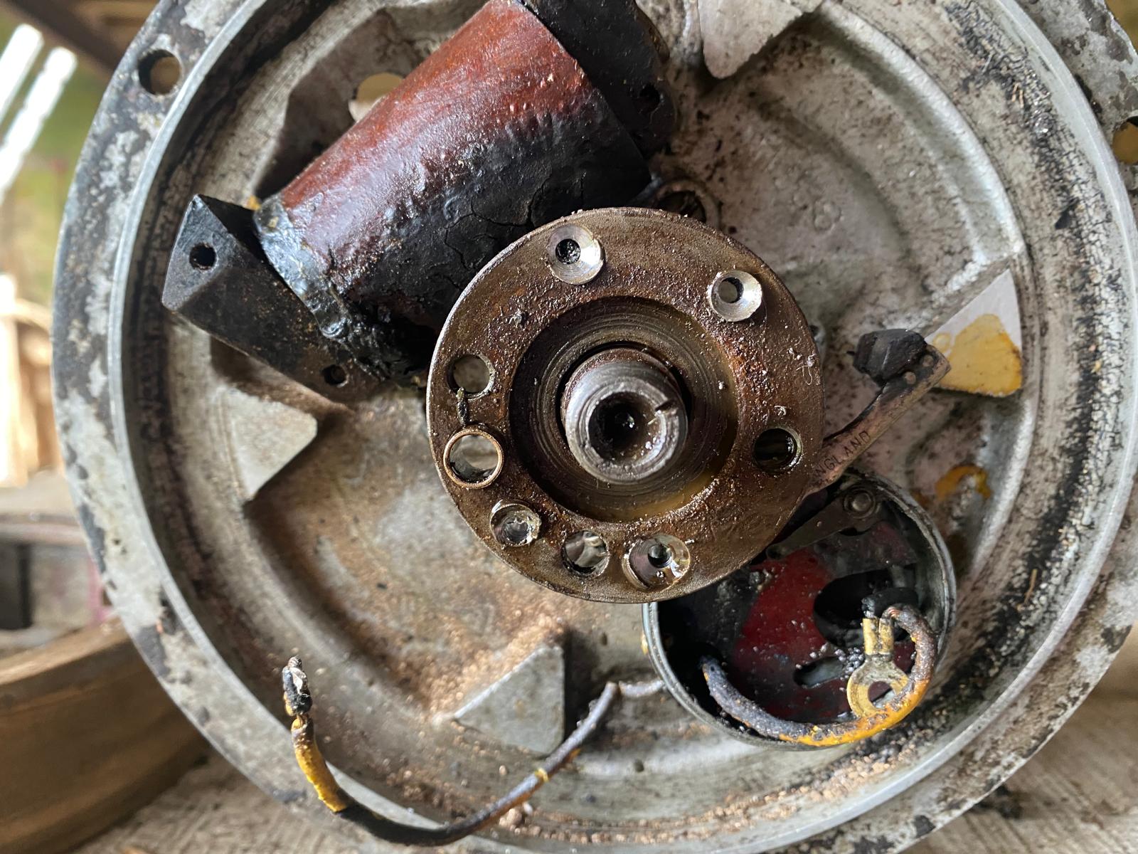
ParticipantMany thanks for yet more useful facts and suggestions. To Andy – yes you are right : my photo shows me holding the outer rim of the flywheel which I have cut away in an attempt to get better access to points and for heat. My post on Feb mentions this . The steel shaft of the f/wheel assy. is still siezed onto the crankshaft.
To Grahame: Thankyou for telling me about Mr Kettering. The site of DENSO shows a neat drawing
of the circuit. I find that Mr Kettering was American, probably not connected to the town in
Northants – which I know well having lived in Market Harborough for may years. Thanks also for pointing out that a six volt ign. coil will be just as good as 12v. I happen to have a 6v recharg.
battery salvaged from some long forgotten scrapped machine
If I might digress, I am intrigued by the need for contact breaker points in the system. On my 2 – stroke strimmer and my Briggs & Stratton 4 – stroke lawn mower. the ign, coil is similar to Villiers, and the magnet on the flywheel whizzes past it (as close as card thickness) and this makes a spark; there are no opening contacts and, I think, no capacitor. Similiarly, on DENSO circuit for Mr Kettering, no capacitor is shown. In the Old Days I used to think that a cpacitor in this sort of circuit was included to eliminate high frequency static which would interfere with reception on the newfangled television sets. Maybe that was for some other machines.
Best wishes to all……….DaveFebruary 22, 2025 at 10:48 am #43438sidevalve5ParticipantHi Dave,
Many thanks for the post. Just to clear up one point about ignition systems on small engines and tractors. They all work along the same principle with a current flowing through the primary windings of the coil generating a magnetic field. Which in turn saturate the secondary windings with lines of magnetic force. When the current flowing through the primary is interrupted, the magnetic field rapidly collapses, which cuts through the secondary, generating a very high voltage which seeks a path to ground. This arcs through the spark plug electrode gap, producing the spark that ignites the fuel/air mixture.
Obviously the higher the low tension voltage in the primary, the greater high tension one is generated in the secondary, thus a bigger spark. With a points/condenser system, just as the points open, the current that was flowing through them seeks a path to ground. The primary coil has a degree of resistance which prevents this. During the opening sequence, the points have a tiny gap and the current can arc and go to ground through that, its an easier path than through the primary windings. The purpose of the condenser (a capacitor in all but name) is to take the current away from the points as they open and store the electrons until the points close again when the current will then flow though the primary. The capacitor has two functions, to prevent arcing at the points and to store electrons so they can be used to boost the current when the points close. More current though the primary and the speed at which the current is stopped from flowing through the primary increases the rapidity of the collapse of the magnetic field which generates a higher voltage in the secondary. The condenser is a vital part of the points system and one that is often over looked when a service or overhaul is carried out. I know this to my cost, wish I had studied ignition systems in more detail when I was younger. I got to the level of understanding the principles, but not how the different components operated in unison and the actions of each upon the others. Could have saved hours of trying to start motorcycles, garden tractors and mowers. Have found from experience and research small engines need a 6mm air gap spark to operate well. Under cylinder compression conditions, it is harder for the HT current to pass a gap. So for it to pass say a 0.025” gap consistently and with sufficient intensity under pressure, a 6mm air spark gap is a reasonable equivalent. A spark from a plug resting on ground is no test at all.
In the Kettering system the primary is supplied with a permanent low tension current from a battery. With magnetos, the current is supplied when the magnet passes close to coil of copper wire wrapped around a soft iron core. Lines of magnetic force that go in one direction are produced in the iron core as the north end of the magnet passes over it. These lines change direction when the south end passes over. The point at which the lines of force change direction is called flux reversal and in that instant a voltage spike occurs in the primary and it is when the points open. In the transistorized module you have mentioned, there is a sensor that ‘sees’ the flux reversal, the sensor operates the transistor, which is in simple terms is a switch, just like the points are. Current is stopped from flowing to the primary. The big advantage of the transistorized system over the points/condenser type is the time it takes to stop the current flowing through the primary is almost instant and complete. The collapse in the magnetic field is more rapid, the voltage generated in the secondary higher. With points there is some milliseconds where the current is going to ground through the contact surfaces just as they part, even with a good capacitor. The collapse in the magnetic field is not as rapid.
Have had an 8mm air gap spark from a transistorized module and modern engines are generally easier starters than the old stuff us silly buggers mess about with. But have found as long as a spark of 6mm is obtained with the lower state of tune of an industrial engine, it is perfectly adequate.
To stop interference to TV’s there is a resistor in most plug caps. If you had a very weak spark, you may use a non resistor type. But have found if I achieve a 6mm spark, the resistor type is OK.
If you still want to do a Kettering system, think you will need a two wire 6v ignition coil. In the UK they are available on ebay as cheap as chips, presume its the same in France. Personally if the replacement flywheel is the same as the original, I would still get the hub off and take it from there. Would not be keen on using the machine without fan cooling and the affect of the flywheel inertia. If the coil tested good, would fit a Meco unit. Maybe if the coil was duff, I could contemplate a total loss battery system. The faff of the limitations of the battery would put me off. Much prefer to get it out of the shed, check the fuel, turn it on, choke, tickle, a pull on the rope and off she goes.
Phew, hope I have explained everything in terms you may understand. Expect an electronic engineer would do a better job than me at it. Off now to continue working on a nearly new MacAllister strimmer that is very hard to start because it has a 4mm spark. It is a piece of Chinese plastic crap, but have managed to get the coil off. Got to see if I can get an after-market replacement. Am a big fan of transistorized ignition, but have found a few that underperform. Am not sure if the vibration and heat generated by a small engine damages the circuit components over time. I have no way of testing them, so its just a replacement job.
Grahame
February 22, 2025 at 11:34 am #43440ParticipantDave , any chance you could post some clear and precise photos of exactly what you have left on your crankshaft.
Andy.
February 24, 2025 at 5:59 pm #43455ParticipantHi Andy,
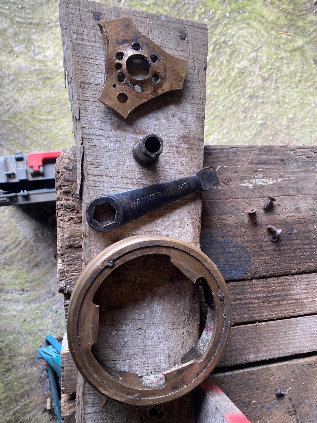
Here are a couple of photos of story so far. Visiting family have helped me dismantle the old boss which, as you can see from the photo, is still stuck on the crankshaft, and we now have prepared my ebay flywheel to replace it without disturbing the boss, and hence timing.The next phase is to reinstall the points and check the timing and, if OK, wire in a Kettering type ignition system. This way we abandon the Villiers coil and capacitor, using only the points to time the spark.
Best wishes…… DaveAttachments:
February 24, 2025 at 8:35 pm #43460ParticipantDave , personally I would give it one more go at removing the boss give it as much heat as you reasonably can , and immediately pour cold water over it , if it doesn’t “sizzle” then apply more heat and repeat , then try your puller , tighten it up , and give the puller a brisk tap with your hammer.
There’s nothing to say your existing coil/condenser have gone , could still be OK, just remove them out of the way before applying the heat.Andy.
March 3, 2025 at 1:18 pm #43468kevm
ParticipantIf the remains of the flywheel wont come off with a puller you will have to carefully cut it off and split it with a grinding disc.
IF the crank isn’t ruined then there is no reason why you shouldn’t just fit a new coil, condenser and points and away you go.
Way cheaper, and less bother than messing with coils and batteries.March 3, 2025 at 3:11 pm #43469ParticipantMany thanks to Andy and Kevin for their posts.
After great attempts I am sure that I will not be able to get the flywheel off the crankshaft.
Cutting it off with an angle grinder does not appeal, and would need a correct replacement and the need to set the timing
The plan is to take the remains of the brass wheel off the crankshaft (drill out the rivets :see photo) and replace it with the wheel from a flywheel assy from Ebay (cost £17) Before fitting the replacement wheel I will have access to the points but not to the coil fixing which is screwed from the back of the armature plate. The original cam on the flywheel boss should be correct for
the points timing. Proceeding to the Kettering system, I will not connect the capacitor or the coil, as these will be fitted externally, and the coil needs one wire from the points. A coil
will cost about 30€ compared to th VilliersParts rewind for £80 plus carriage to & from France.
I already have a battery and of course it will have to be recharged on the bench
Thanks again for your interest: no doubt there will be ups & downs. I will, if I may, let you know how it goes
Regards.Dave SeabrookMarch 17, 2025 at 7:01 pm #43537ParticipantModest progress on flywheel assembly. I and Mark ,my long suffering associate, have re-installed the points assembly, and determined that points appear to open at prescribed 5/32″ before TDC. We await delivery from UK of coil etc to determine that there really will be a spark.
Meanwhile, looking at the cutter bar, we are short of one Blade Pad – the triangular casting that is adjusted to keep the blades in contact with the “fingers” (don’t know correct term) I wonder if anyone knows a supplier, or has one for sale.
Regards Dave SeabrookMarch 18, 2025 at 7:16 am #43541ParticipantGeorge at villiersparts has a reasonable stock of Allen Scythe parts , he’s well worth a try.
Andy.
March 25, 2025 at 9:44 am #43573ParticipantThanks to Andy – my enquiry to Villiersparts gained the response <no stock>. Never mind, my
search continues, and meanwhile no doubt I can construct something to do the job. Not too difficult to change over if I find the right thing.Dave
-
AuthorPosts
- You must be logged in to reply to this topic.
VHGMC Forums
Got a machine and need info or have a question? Then a post in the VHGMC forums is a great place to start!
Who's Online
There are no users currently online