Home › Forums › The Main Forum Area › General talk and discussion › Norton Big 4 Spark Plugs
- This topic has 18 replies, 5 voices, and was last updated 12 years, 1 month ago by
 charlie.
-
AuthorPosts
-
October 19, 2013 at 4:26 pm #1403
 vhgmcbuddyMember
Anyone out there with the industrial version (i.e. non motorcycle) of the 633cc side valve Norton Big 4 who can offer any advise on what spark plug they are using?
Tried to fire up my Trusty today, but it is as dead as a Dodo!!. Plenty of fuel getting through the carb. The magneto is creating a spark, although it does look a little weak, so this maybe an issue, but there is something which doesn’t look right about my spark plug.
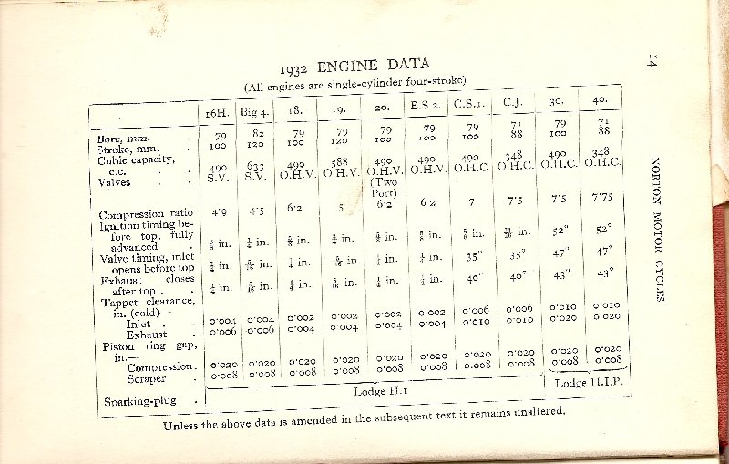
In the motorcycle repair manual for the Big 4, it states that the correct spark plug is a KLG KS5, which is 18mm diameter and has a reach of 1/2″. I have an NGK AB-8 plug which also has a reach of 1/2″, but the actual threaded hole in the cylinder head is 3/4″ deep, which means the end of the spark plug is recessed in the hole, rather than being level with the inside face of the head. I know that the cylinder heads on the motorcycle and industrial versions of the Big 4 are different, in that the cooling fins are aligned differently, but I am also now wondering if the industrial version cylinder head is actually thicker, requiring a spark plug with a 3/4″ reach.
Any help would be greatly received, as after several hours of winding on the starting strap and pulling, my arms can’t take much more!!!Cheers
Sean
October 19, 2013 at 4:45 pm #1404 will-haggleParticipant
I should clean and gap the points and the plug you have, so that you get a nice fat spark. I’ve only got a book on the Motorcycle Engine, so I can’t tell what plug your version should have….
Attachments:
October 20, 2013 at 9:54 am #1480 trusty220Keymaster
The book on the industrial version states that the plug should be a KLG M80. However, did you also realise that there were two heads fitted to Trusty products? The Steed Mk2 had an aluminium head with the fins running from back to front (this is possibly a motorcycle head) and the 2-wheeled Trusty had a cast iron head with the fins running from side-to-side?
There are other differences between the two versions as well;
Type 1: If you have fins running from side-to-side on the head, cast iron head, valve chest cast into the cylinder barrel, Wico A magneto, parallel sided crankshaft with keyway. This is the type used on Trusty 2-wheel tractors from 1947 onwards, generally known from the “ZT” prefix to the engine number. This is the Industrial version.
Type 2: This has fins running from front to back on the head, aluminium head, aluminium valve chest casting separate to the cylinder barrel, BTH magneto, short tapered crankshaft with a thread on the end. This is the type fitted to the Steed Mk2 (not MK1) and has a specification closer to the motorcycle engine.
Obviously some of the settings will be the same for both, but not necessarily, so it may be best policy to decide which spec. is closer to the engine that you have.
I have a copy of the Industrial manual if you need info.October 20, 2013 at 12:32 pm #1495vhgmcbuddyMemberThanks chaps. As the KLG M80 has a reach of 1/2″, my NGK AB-8 should be fine. The plug is brand new, so the Wico A magneto is probably in need of attention. My engine is definitely the Type 1. Would be interested to know what you industrial manual states about the timing Geoff, as I have set the engine up based on the info in the motorcycle manual, which may not be strictly correct.
October 20, 2013 at 1:02 pm #1496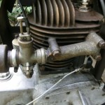 wristpinParticipant
Possibly totally irrelevant but my Dennis “hates” NGK plugs. Will run once with a new one but then no more. A while back there was a post on this forum ,from I think Charlie, explaining that on old KLGs etc the centre ceramic insulator was glazed and “self cleaning” where as on modern plugs it is not and in “our” applications is prone to fouling and shorting out the spark.
May be worth looking in auto jumbles etc for some old plugs. At present I’m running the Dennis on a “replica” plug from Villiers Services (don’t confuse with Villiers Parts) and it has run well on it all season. Would give you a link but their site seems to be down.October 20, 2013 at 3:09 pm #1507 charlieKeymaster
Reference to old glazed and modern non glazed plugs came from The Green Spark Plug Co website.
October 20, 2013 at 4:48 pm #1522trusty220KeymasterThe timing is set with the points opening at 3/8″ before TDC. The points gap is 15 thou.
October 21, 2013 at 8:42 am #1573vhgmcbuddyMemberThank you for your comments gentlemen. I am going to get the magneto checked over by a professional as it probably needs remagnetising after 66 years!!
October 21, 2013 at 9:12 am #1579wristpinParticipantVilliers Services site, back up and running.
January 12, 2014 at 7:09 pm #5099vhgmcbuddyMemberI have now had the magneto professionally refurbished. It has been fitted with a new condenser and coil. The original condenser was found to be completely shot and the coil was way past its best. According to the test results following the rebuild, the minimum rotor speed that the mag needs to produce a consistent spark when cold is 138rpm (so 276rpm engine speed). After heating to 50 degrees celsius, the rotor speed needs to be a minimum of 170rpm. The spark remained consistent all the way up to 3000rpm.
So, I fitted the mag back to the Norton and after 20 minutes of pulling on the starting strap, it did eventually fire, once!!! Not to be detered, I continued pulling for another 10 minutes before it sputtered into life, albeit for only 5 seconds, but I’ll take that as a victory!!!!
I have set the timing so that the points begin to open at exactly top dead centre, as I believe this is normal practice to make starting easier (allegedly!!!). Would I be right in thinking that the quoted figure of 3/8″ before TDC relates to once the engine is running normally and that this is achieved by adjusting the lag angle. According to the Norton engine manual 3/8″ equates to 28 degrees, so is this what the lag angle should be set to?
Now I am confident that the mag is working as it should, I think the carb needs some adjustment. The carb is an Amal 225. I have read previously on this forum that the main jet needle should be wound in until fully seated and then wound out by one and a half turns, which I have done. There is also an air adjusting screw fitted at the air intake end of the carb, running parallel with the body. Does anyone know what position this should be set in?
Finally, I was testing the engine without the air cleaner connected up, so could this cause the engine to get too much air and make it difficult to start?As usual, any advice on the fine art of magneto setting and carburetion would be greatly appreciated.
Cheers,
Sean
January 12, 2014 at 7:25 pm #5101wristpinParticipantAir cleaner-put it on as it will richen the mixture slightly.
Timing – hopefully there is someone on the forum who knows the precise method for your setup but from distant memory the engine should be rotated until the impulse trips and then turned back to the point at which the contact breakers just starting to open and the timing set then.
As I said, a distant memory and not specific to your engine!January 16, 2014 at 4:30 pm #5169trusty220KeymasterWhen I set up my engine after cleaning the carb I set both jets to 1 1/2 turns out. That should be sufficient to start it, then once it’s running you can adjust firstly the main jet (engine speed needs to be 1500>2000 revs approx.), then drop the revs down slowly so that it drops to tick over. The best way of doing this is to turn the slow running adjustment screw in a few turns to open up the butterfly, then you can slow the engine down in a controlled way with gradual adjustments to this screw and if it looks like it’s about to stop you can adjust the slow mixture screw accordingly. This gives you plenty of time to make the adjustments without having to rush or continually revving it up and down. As a final check, with the engine on tick over just increase the throttle as if you were going to drive away- if it splutters, hesitates and then picks up you need more fuel, so richen up the slow running mixture screw.
The slow running mixture screw not only keeps the engine running when on tick over, it also assists the engine to increase speed ( a little like an accelerator pump ); it is often overlooked when adjusting the carb, but it is the most important. If you look in the venturi you will see that there are three holes spaced along the inside, roughly where the butterfly comes to rest. It is these holes that control the tick over and acceleration of the engine, and they are adjusted with the slow running mixture jet.
One other thing to check is the timing, which is crucial. Somewhere near, in my experience, is not good enough. It needs to be set at 3/8″ BTDC with the points just opening, anything else and it just doesn’t run correctly.
I hope that helps!January 16, 2014 at 6:44 pm #5175vhgmcbuddyMemberThanks for the advice Geoff.
From what you have said, my timing is obviously way out. The points currently start opening at TDC, so if am understanding what it says in my Wico Series A manual, the impulse coupling will then retard the spark by whatever the lag angle is set at, so this will mean that the impulse spark is some degree after TDC, which would explain the complete lack of thump, thump, thump noises coiming from the exhaust!!!
My next question is, how do you advance the timing on a Wico Series A? The manual I have tells you how to adjust the lag angle, but when it comes to timing the advance spark it states “The magneto is coupled to the engine when the points are just opening” The problem is, the sprocket on the mag can only be fitted in one specific location, i.e. you can’t loosen the sprocket and rotate it a bit on the magneto shaft. Also, the sprocket on the engine is keyed to the inlet valve gear cam, so this can’t be adjusted. I have tried removing the magneto drive chain and then rotated the magneto by one tooth of the sprocket and then refitted the chain, but this results in the timing being way too early.January 20, 2014 at 2:47 pm #5267trusty220KeymasterWhat you need to do is to take the sprocket off the magneto. You will find that the nut is a left hand thread (I think) and the shaft is tapered with no keyway. Do not try to lever the sprocket from behind because you will b******r the bearings in the mag, the only way to do it is to pull it off with a puller, pushing on the end of the shaft.
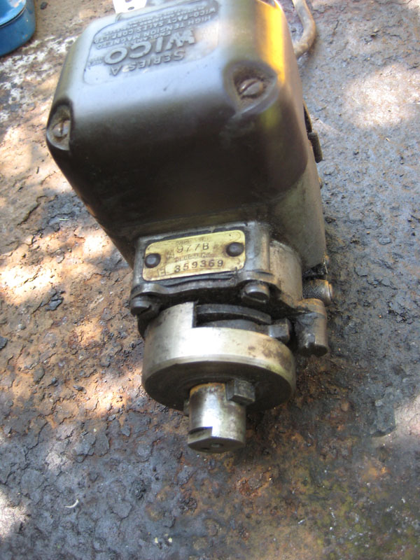
Once the sprocket is loose on the shaft you will find that you can turn the engine without the rotor in the mag moving- set the engine at 3/8″ BTDC, then turn the mag in the direction it normally runs in and stop when the points are just opening. Replace the sprocket and timing chain on the magneto shaft and with a small socket give the sprocket a sharp tap to seat the sprocket on the shaft taper. The engine is now timed accurately.January 20, 2014 at 7:06 pm #5272vhgmcbuddyMemberUnfortunately Geoff, the mag on my Norton is quite different to what you describe. The pictures hopefully show what mine is like.
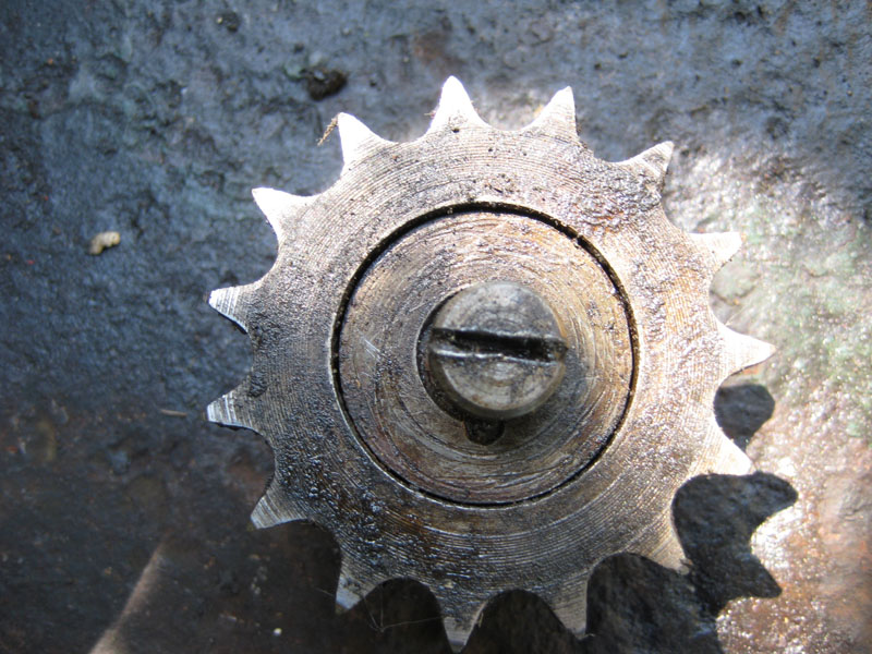
Basically, the sprocket has two notches in the back which locate over the lugs on the impulse coupling. There is then a metal disk with an off centre locating pin on it (you can just see the back of the pin below the screw head in the photo of the sprocket) which fits in the centre of the sprocket. The pin on this disk fits into a hole in the end of the magneto shaft so that it cannot spin. A left hand thread screw then attaches the lot to the magneto shaft.
All of the above means that the sprocket will only fit one way on the magneto shaft. So, as far as I can work out, I need to rotate the whole impulse mechansim without rotating the magneto shaft, but I am not sure that this is even possible.Attachments:
-
AuthorPosts
- You must be logged in to reply to this topic.
VHGMC Forums
Got a machine and need info or have a question? Then a post in the VHGMC forums is a great place to start!
Who's Online
There are no users currently online