Home › Forums › The Machinery Forums › Pedestrian operated machines › JAP 2a flywheel removal
- This topic has 31 replies, 4 voices, and was last updated 3 months, 3 weeks ago by
 charlie.
-
AuthorPosts
-
July 15, 2025 at 10:24 am #43892
 sidevalve5Participant
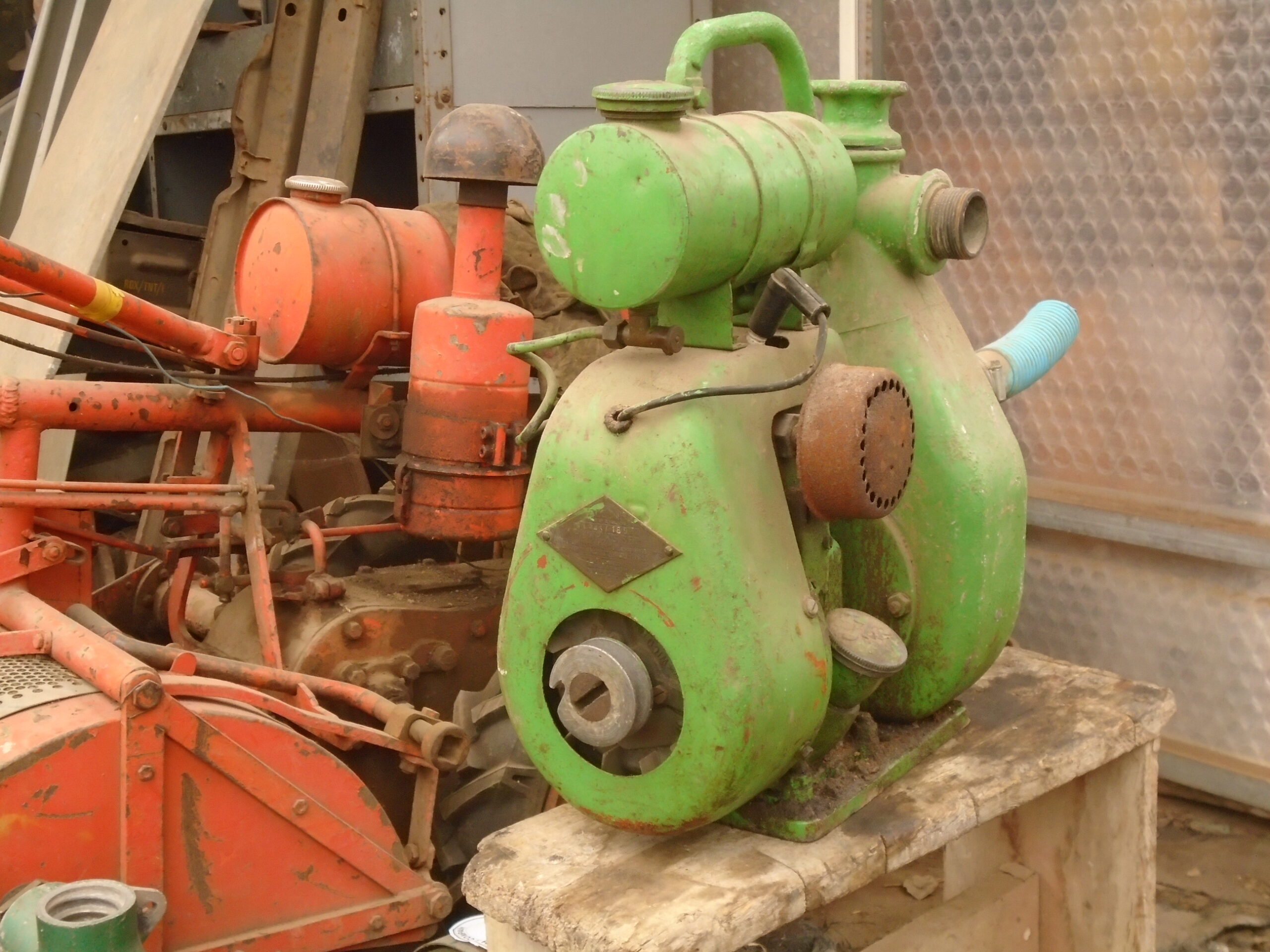
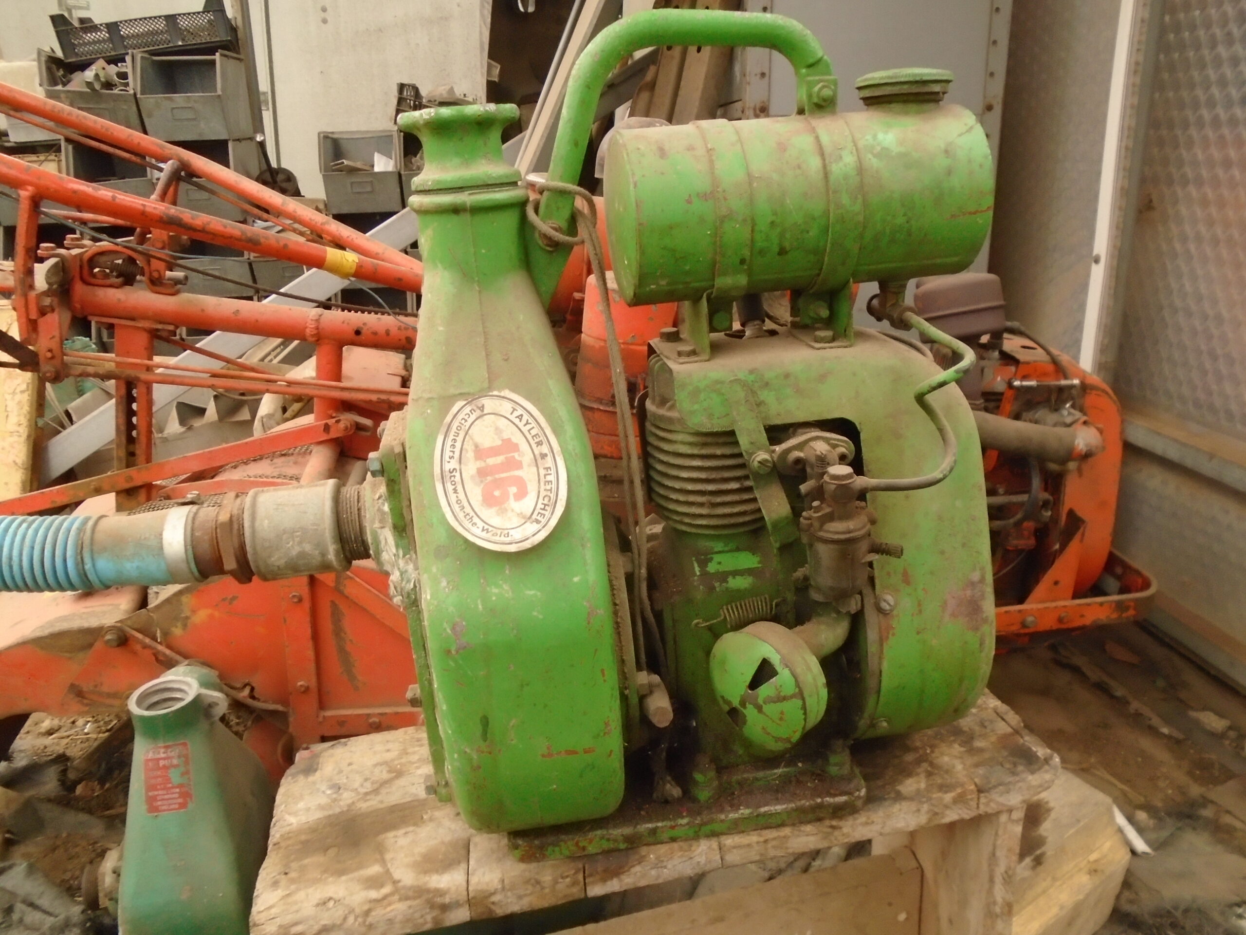
Have recently got a JAP 2a attached to an Alcon pump. Some may be aware of this from replies in a previous forum string. But wish to start a new subject on the engine and not the pump.
The exhaust valve was stuck open and managed to tap it closed through the plug hole. But still no compression, I think the engine has not fired in decades, so am going to take the head off to see if the rings are stuck. Or it’s something else.
There was no spark and a quick resistance test from the HT lead to ground raised the possibility of a breakdown in the secondary coil windings. Cleaned and adjusted the points through flywheel access hole, still no joy, but this was anticipated. Which brings me to the reason of this post. I need to take the flywheel off and have not done this on a 2a before. Am I correct in assuming that the roll pin behind the starter pulley needs to be knocked out and then I can fit a puller to get it off. Then I need to lock the engine to undo the large slotted bolt, it is a right hand thread. Lastly and most importantly, do I need to make a puller so I can use the 3 bolts in the flywheel to get it off. Or can I use the method I do for Briggs & Stratton’s, a lever behind the flywheel and the point of an air chisel on the crankshaft centre. A bit of pressure on the lever and pull the trigger. Or is there another way.
July 15, 2025 at 9:30 pm #43893andyfrost
ParticipantGrahame , every 2A I’ve ever worked on the flywheel is only held on by the starter pulley , you should see a large slot in the steel embossed inner part , I have a nut welded on a piece of steel that fits snugly into that slot and use an impact gun , it’s normal righthand thread, very often the flywheel will come of with a VERY SLIGHT tap from behind , it’s a straight shaft with key , so no locked on tapers , or air chisels to worry about. Can’t say I’m sure what you mean by the rollpin , it’s something I’ve never come accross.
Andy.
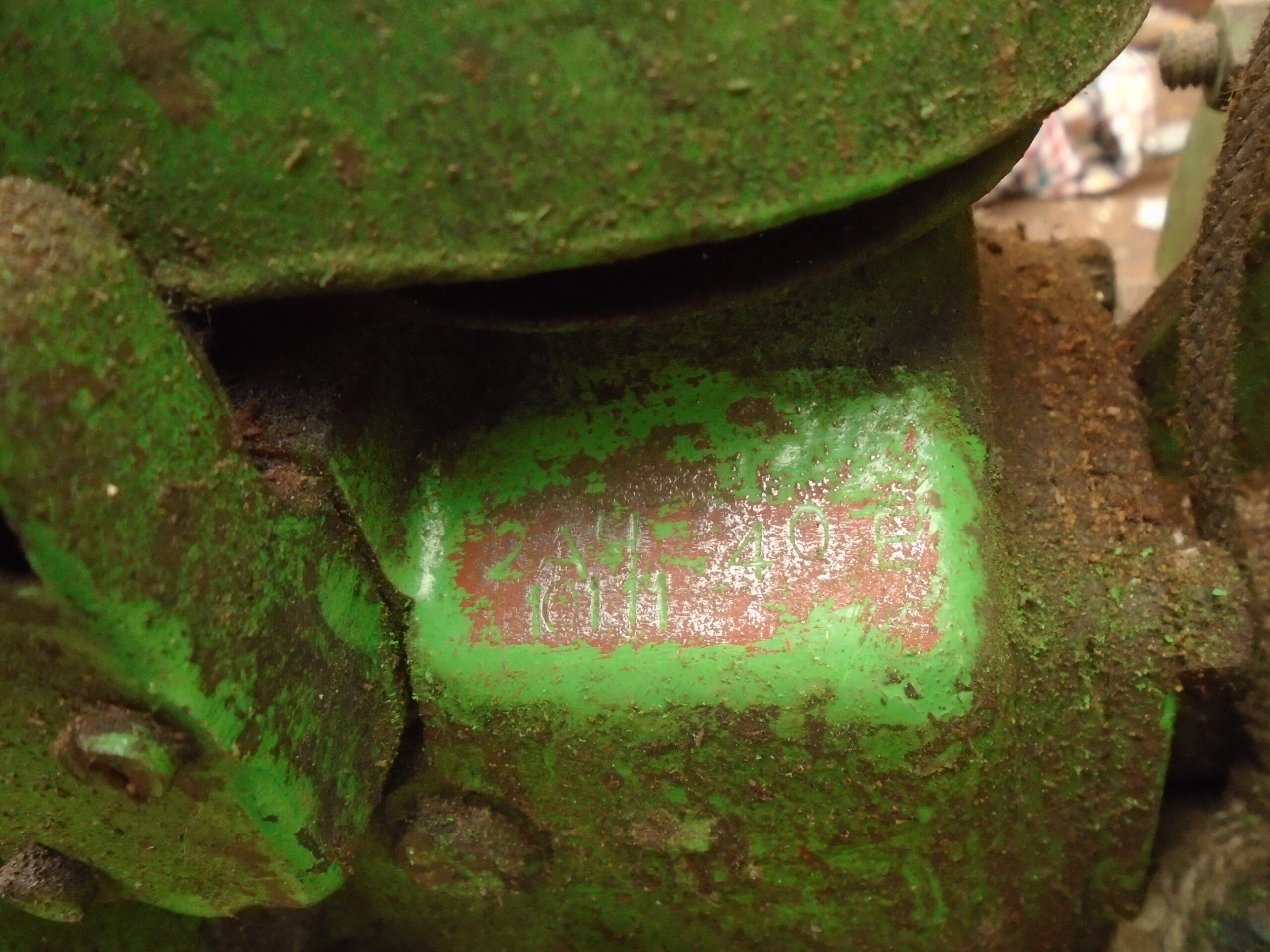
July 16, 2025 at 10:02 am #43896sidevalve5ParticipantMany thanks Andy. Am going to have a go at taking the flywheel off at the weekend and will take a picture of the roll pin. It looks like there is a sleeve or spacer behind the pulley and the roll pin would lock it in place. The first numbers on the crankcase are 2AH, which I think means it’s a 2A manufactured in 1951. But the H is higher than the 2A and missing the bottom right leg of the font. Will take a picture of that too. Could you please confirm that the aluminium pulley will be attached to the slotted steel bolt. So all I have to do is lock the engine and undo the bolt. Have a Warrington hammer that fits perfectly inside the slot, so just need to keep it in really tight and turn. Have an attachment to a slide hammer puller that has 4 slots in it, so bolts at both 120 degrees and 180 degrees can fit. It was in the back of my mind I had something buried in a toolbox that would work and just found it yesterday after a rummage. Think in the first instance am going to try to use it as it is similar to JAP’s specialist puller. Did not know it was a straight shaft and key, was under the impression it was a taper shaft. Great to get that info too.
It looks like the engine was supplied to Alcon painted in red oxide and Alcon then covered everything in lime green. The inside of the cowling still has the red oxide paint on it. It does not look like it’s done much work and been kept in the dry, so will be a little surprised if the coil is duff. But until I get the flywheel off and test at the pickup, I will not know. Am actually not bothered if it is as I have been waiting to put an external single wire energy transfer coil onto such an engine. Know the theory, but have not put it into practice and this little JAP is an ideal candidate. Mocked up the coil I have yesterday and it will fit at the end of the fuel tank. Will keep you posted how I get on, but I will not be doing the full overhaul in one hit. Summer is the growing season when I use my machines, winter is tinkering time.
Best wishes and thanks again,
Grahame
Attachments:
July 16, 2025 at 12:06 pm #43899ParticipantGrahame , the starter pulley(the alloy part) and the steel inner(with the slot) are as such one unit , and upon undoing will come off as a complete unit , it’s then a simple task of drawing the flywheel off its staight shaft , in my experience they are very easy to remove.
Very recently I did a 2A on a Bulldog for a collector friend of mine , fortunately the mechanicals were excellant , the coil was duff , and as he wanted 100% reliability , I fitted a complete new ignition system , all parts are easily available , it started and ran superbly , and he’s delighted with it.Andy.
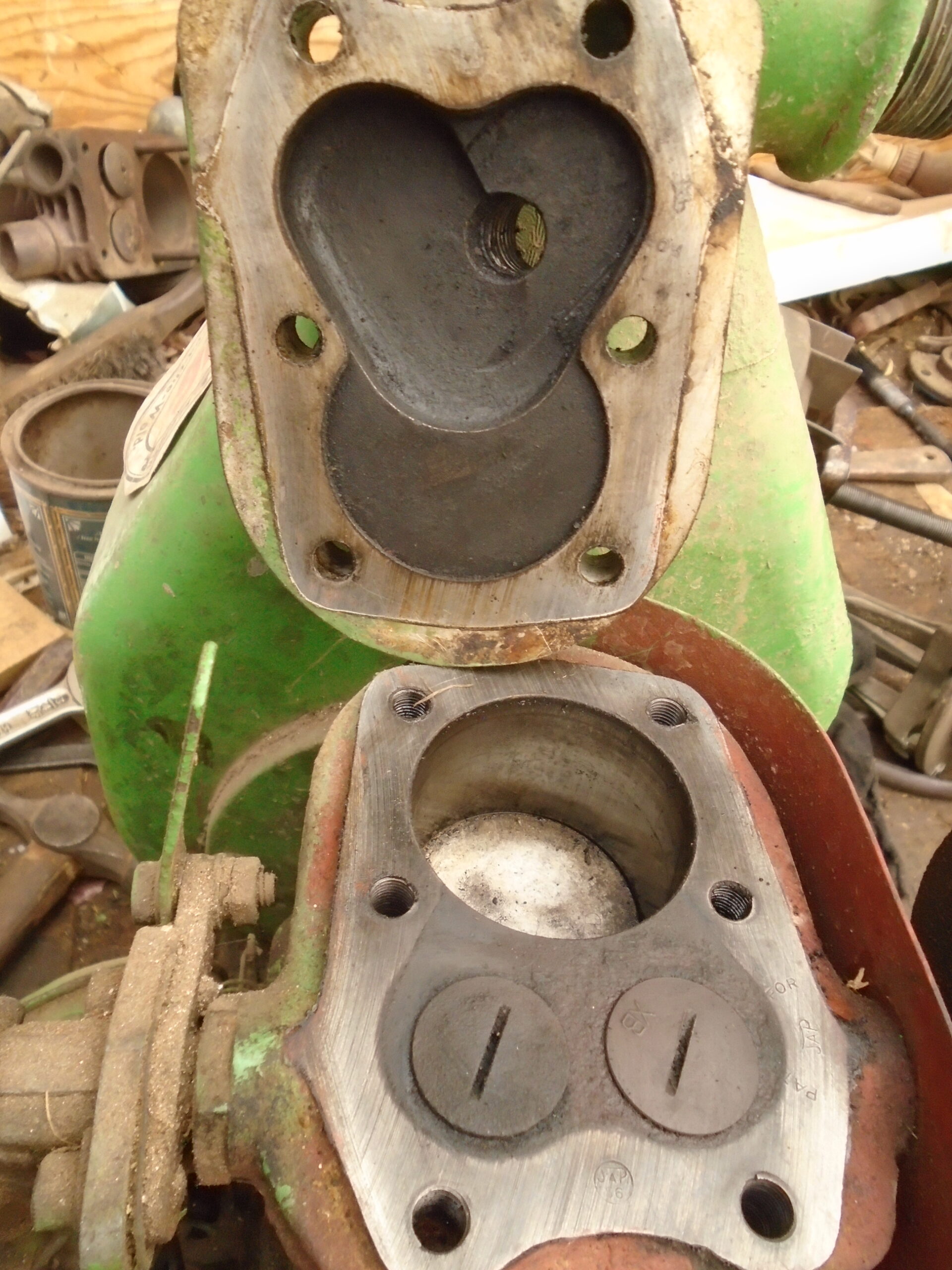
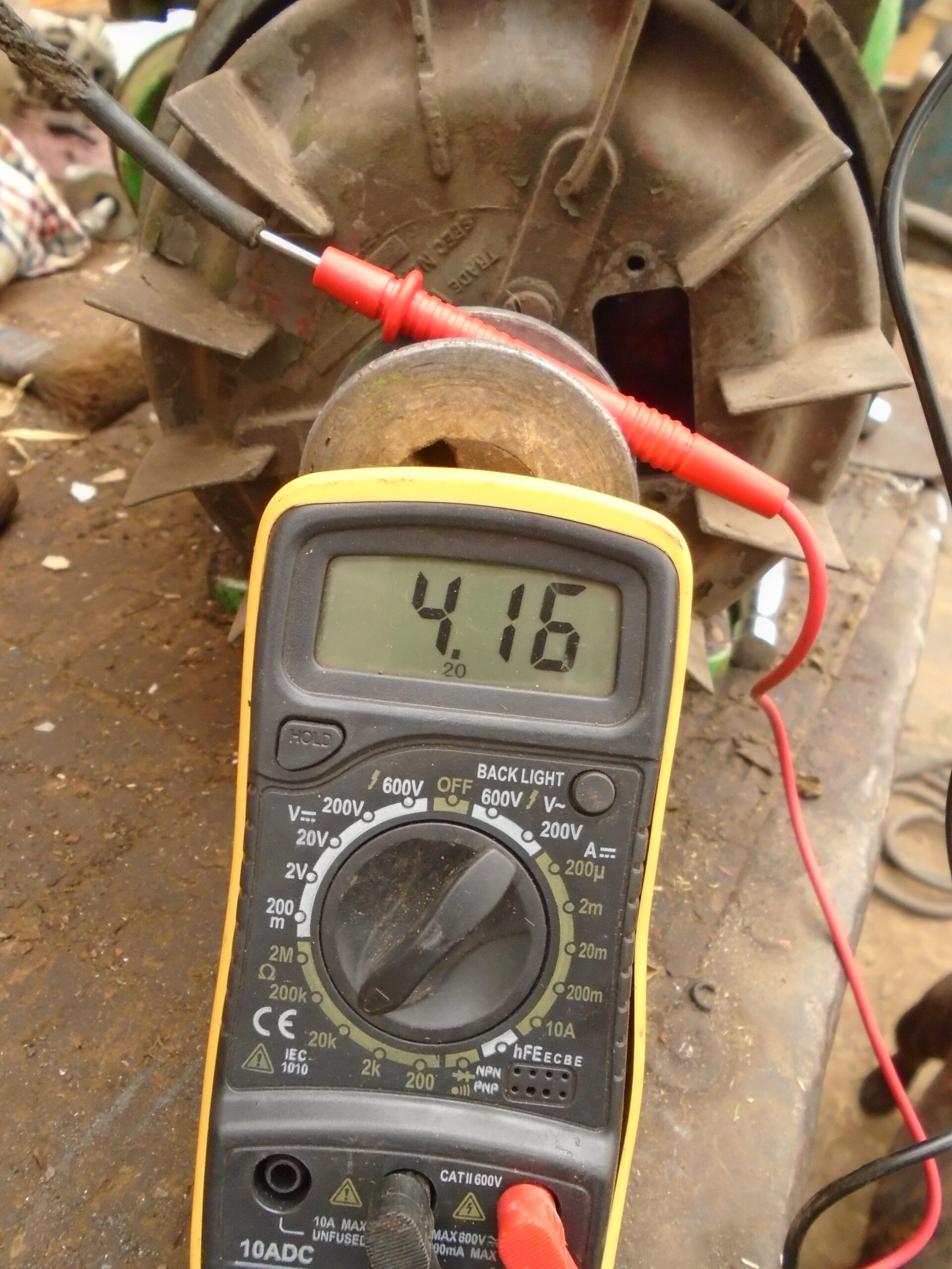
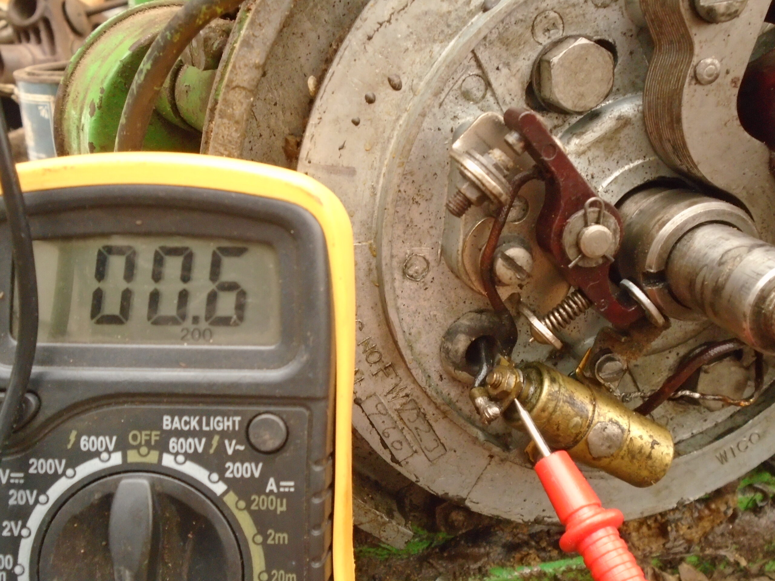
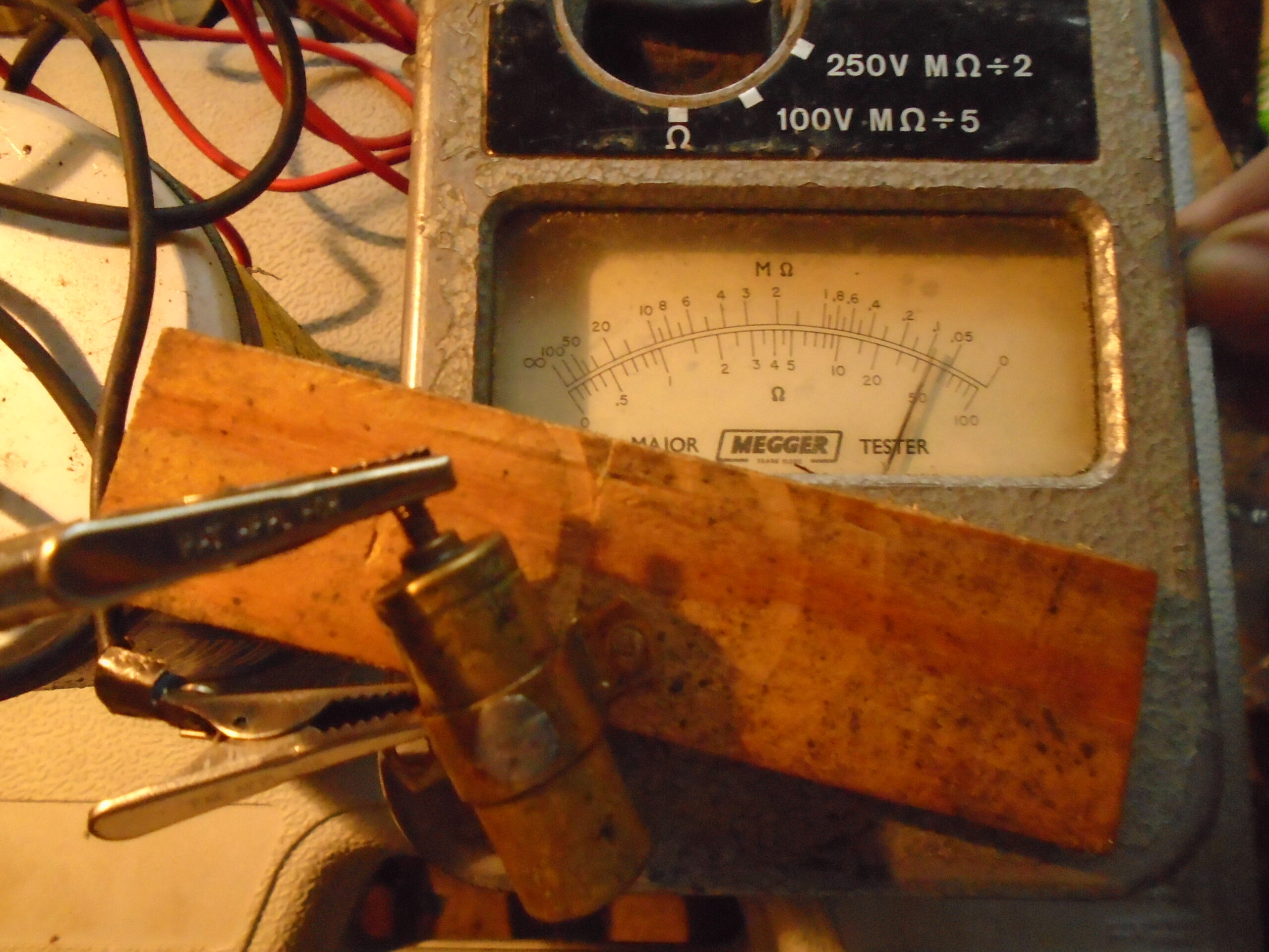
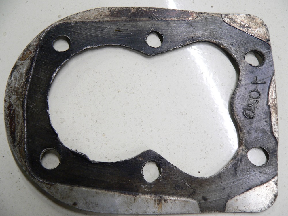
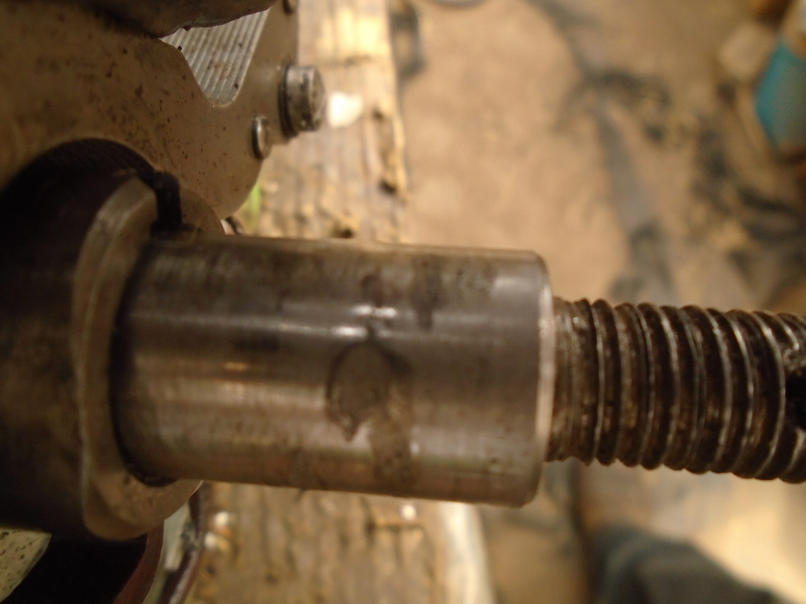
July 20, 2025 at 10:52 am #43914sidevalve5ParticipantHi Baz. Got the flywheel off yesterday, had a right game with it. Think Facebook only allow one photo in a reply to a post, so will send what I have in a succession of replies to illustrate the matters better. Believe the year of manufacture to be 1951 with the H (missing the bottom left leg) after 2A. Do not think the engine has done much work because there is no wear in the bore and what little carbon there was on the piston and head mostly wiped off with a rag. Took the head off, there was no gasket. Do you know if this is correct. I do not think the cowl has ever come off because the bolt threads for the tank straps and carrying handle still had the lime green paint I think Alcon put on at their works. Believe Jap supplied the engine covered in red oxide as it is inside the cowl and some of the cylinder fins. Put a large socket in the bore and replaced the head so the engine was locked. Knocked of the three sections of the roll pin and the pulley undid by hand! Half undid the three set screws on the flywheel so I could get the legs of a side hammer puller underneath. No go, was worried about damaging the threads on the flywheel. Went to see a mate who had 2” long ¼” Whitworth bolts and put these in a four slots attachment I have for the puller. After a lot of effort, it came off and immediately saw the reason why it was on so tight. The surface of the shaft and the hole inside the flywheel seemed to show signs of a seizure, yet the shaft does not rotate inside the hole. I think either there was swarf or similar on/in it during assembly, or a machining flaw and if known, may explain the roll pin. Initial continuity HT test showed a variable reading, think the black probe was not on a good ground. Have tested again yesterday, both HT and LT resistance is OK. Tested the condenser with a Megger, it failed. I do not use tradition condensers anymore, use a modern polyester film 630v 220nF/0.22uF capacitor. Was actually hoping the coil was duff so I could try again making up a single wire energy transfer coil system. Am still going to do it, but will take off the existing coil, make a former for a new coil, put the old one back on and complete the engine overhaul. Will test the spark from the existing system, then fit the internal coil I will have made and the external one. Then test that system to see if there is an improvement. Best wishes, Grahame.
Attachments:
July 20, 2025 at 11:00 am #43923sidevalve5ParticipantHi Andy,
Please ignore the text in my last post. Am chatting to a chap in Australia who has done a 2A up and asked him about removing the flywheel too. I did the original text to him, them slightly edited it for you. Copied it to paste into the VHGMC forum box and for some reason (think because I had not saved the Word.doc before editing), although the one to you was showing in the box. When I posted it, the one to Baz went!!! No harm done though, just a little confusing. Yours is below:
Got the flywheel off yesterday, had a right game with it. Believe the year of manufacture to be 1951 with the H (missing the bottom left leg) after 2A. Do not think the engine has done much work because there is no wear in the bore and what little carbon there was on the piston and head mostly wiped off with a rag. Took the head off, there was no gasket. Do you know if this is correct.
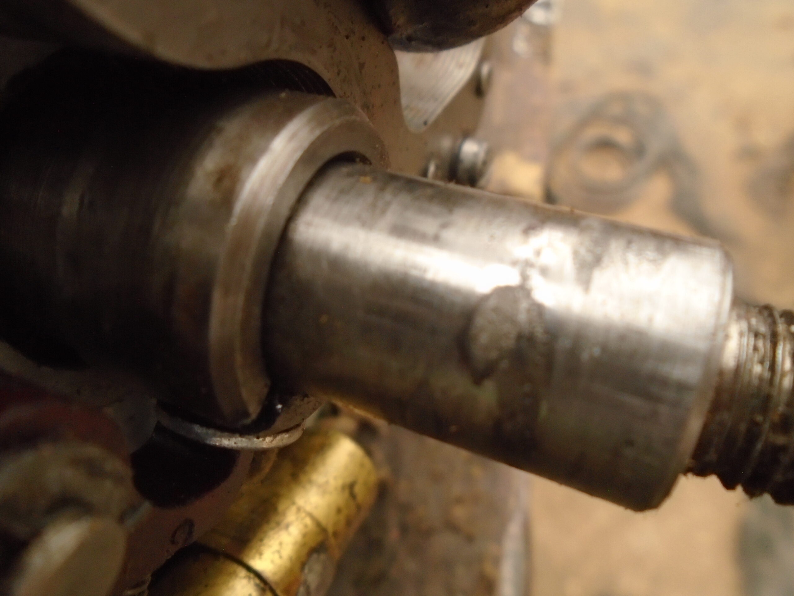
I do not think the cowl has ever come off because the bolt threads for the tank straps and carrying handle still had the lime green paint I think Alcon put on at their works. Believe Jap supplied the engine covered in red oxide as it is inside the cowl and some of the cylinder fins. Put a large socket in the bore and replaced the head so the engine was locked. Knocked of the three sections of the roll pin and the pulley undid by hand! Half undid the three set screws on the flywheel so I could get the legs of a side hammer puller underneath. No go, was worried about damaging the threads on the flywheel. Went to see a mate who had 2” long ¼” Whitworth bolts and put these in a four slots attachment I have for the puller. After a lot of effort, it came off and immediately saw the reason why it was on so tight. The surface of the shaft and the hole inside the flywheel seemed to show signs of a seizure, yet the shaft does not rotate inside the hole. I think either there was swarf or similar on/in it during assembly, or a machining flaw and if known, may explain the roll pin.
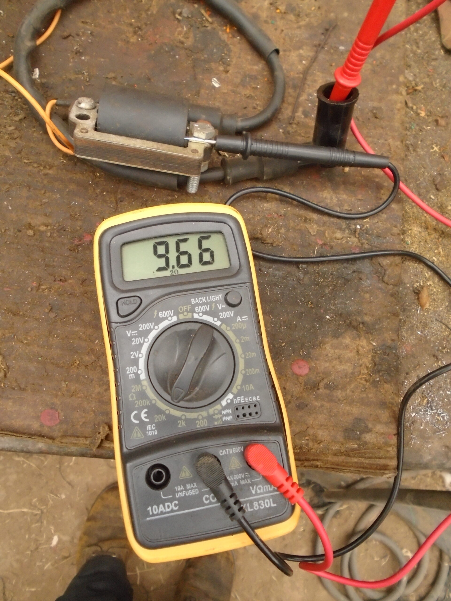
Initial continuity HT test showed a variable reading, think the black probe was not on a good ground. Have tested again yesterday, both HT and LT resistance is OK. Tested the condenser with a Megger, it failed. I do not use tradition condensers anymore, use a modern polyester film 630v 220nF/0.22uF capacitor. Was actually hoping the coil was duff so I could try again making up a single wire energy transfer coil system. Am still going to do it, but will take off the existing coil, make a former for a new coil, put the old one back on and complete the engine overhaul. Will test the spark from the existing system, then fit the internal coil I will have made and the external one. Then test that system to see if there is an improvement. Have attached the external coil I am going to use. All good fun.
Best wishes,
Grahame.
July 20, 2025 at 12:29 pm #43924ParticipantGrahame , you do seem to have made a most simple task complicated , 2As are one of , if not THE simplest engines to work on , as you have now seen , no awkward taper flywheels , keyed timing. Every 2A that I’ve done have always had a head gasket.
I can’t see from your pics , but did the rollpin actually go through the crankshaft , or just through the alloy starter and into the centre boss.Andy.
July 20, 2025 at 10:24 pm #43926davidbliss
ParticipantAndy Yes reckon the roll pin come the bodge it it up brigade as never seen a flywheel nut come loose had alloy break a few times where the rope hooks onto so fitted a new one and found the alloy is just a tight push fit so skimmed a bit off the steel and welded a nut and pressed the alloy back on this makes it so much easier to fit and all that I have seen had head gaskets made from soft 0.055 thou sheet alloy, the only major failure had was a die-cast flywheel with internal metal corrosion causing expansion and came loose from the steel boss causing a slight knock at idle.
Attachments:
July 21, 2025 at 8:53 am #43929sidevalve5ParticipantAndy,
I would agree that a 2A is a very simple engine to work on. Where we will diverge hugely is that because the flywheel was all but welded onto the crankshaft, it was a devil of a job to get it off. Your method would have failed in the first instance. Persisting in it would have damaged or broken associated parts.
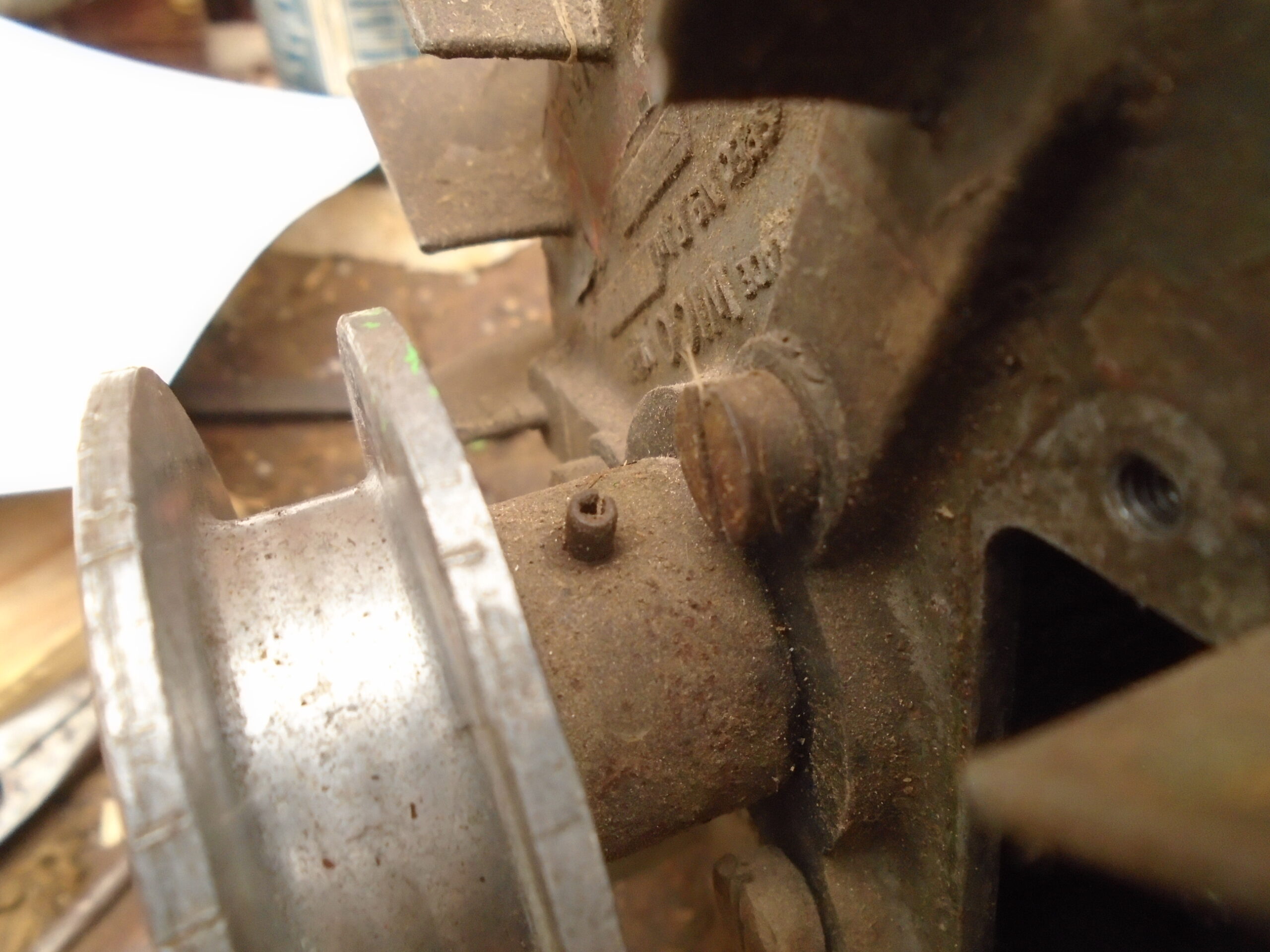
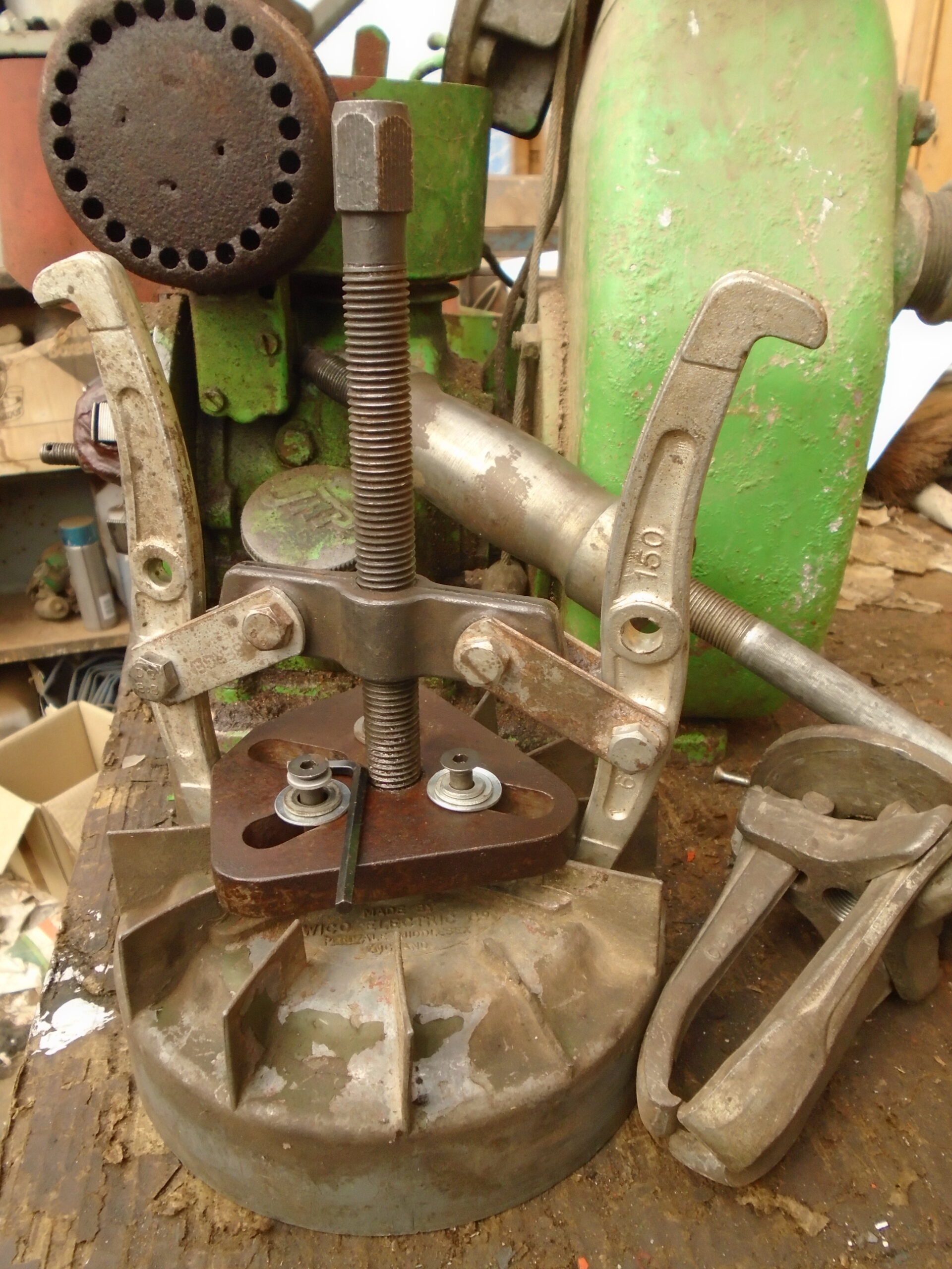
Attached are more images of the state of the shaft and the puller method I used, complicated you may say, but a necessity if the seized flywheel was to be pulled off the shaft. It consists of two pullers, one with the 4 hole attachment that I could fit the 3 whitworth bolts into. The bolts ideally needed to be longer, but this is all I could get hold off on a Saturday morning. Because the side hammer element would not fit as the crankshaft was too close to the centre hole. I got another puller to go on the attachment and placed 2 nuts in the middle hole to act as a centring spacer. It involved a 1/8 turn of the puller hex end, followed by several sharp blows on that end, for another 1/8 turn to be done and more blows. Repeating the process many times until it was free. You may describe it as complicated, I believe that I used care, skill, experience and a range of tools, applying them all in unison to do a difficult job.
Again you may say my ignition testing technique that I have shown in the imagery is complicated. I would contend that it is a simple and quick diagnostic method of establishing where a magneto ignition trouble lay. In this case it was a 74 year old condenser with a wax paper dielectric, the primary and secondary coil windings are fine. Sending the ignition parts away to be tested, or just using the substitution method would have resulted in additional time and unnecessary expense in fixing the problem. FYI, testing took 4 minutes, the cost of the polyester film capacitor and board to mount it on is 45p, estimated time, 15 minutes.
You may say too that my intended fitting of an external coil is complex too. To my mind it is not, however I do concede a rudimentary understanding of mutual induction is required. Am not doing it to fix a failed coil, but to do an experiment to see if firstly, it actually works and secondly, if it does, is it better than a known good original system. I want to find out if winding a primary in my own workshop on a homemade jig and fitting an external coil is worth doing as opposed to purchasing an expensive new one. I could then advise others with greater confidence, as I would have completed the conversion myself. I also get great enjoyment and satisfaction from doing such projects.
Grahame
Attachments:
July 21, 2025 at 9:00 am #43933sidevalve5ParticipantDear David,
Had another look at the engine yesterday and indeed it does have a head gasket. When I took the head off on Saturday I only took a quick look at it, noting it had numbers stamped on the contact face. It was covered in thick green paint. The numbers were an imprint of those stamped on the cylinder and into the soft head gasket. A closer inspection revealed the head gasket.
I also had a more detailed look at the crankshaft and hole in the flywheel. Both had roughness and have started to flatten it off the shaft. It appears to me corrosion, but not from water. Still think something was on the shaft or in the hole during assembly, maybe an acid type material. The good news is that I can flatten it off so the correct interference is restored. Am going to re-fit and take off until I am satisfied the flywheel will come off as it should.
Your positive reply restored my faith in the VHGMC forum. My understanding of a forum is to discuss ideas in an open, proactive and positive manner, I like to engage in this process. I sometimes feel those who wish to obtain information or expand their knowledge and experiences by posting a subject in the VHGMC forum are often met with apathy and/or negativity. You, the hdtrust and a couple of others are the only exceptions. Facebook groups appear to have younger, more open minded members who are willing to positively engage. This does not bode well for the future of the club.
Best wishes,
Grahame
July 21, 2025 at 9:32 am #43934ParticipantGrahame , I never said or meant you were complicating your ignition ideas , I admire you for having a go , and I really do hope it works , It appears to me a sound idea , if the situation happens whereby the original components are not available. Whilst parts are still readily available I tend to go down that route.
I have a large ammount of purpose made pullers , for all manner of engines , obviously if my usual method does not work , I would revert to one of those were I in your position. At least you managed to get it off , which is the main thing with no damage involved , we all have different ways of doing different tasks.
Still confused about your rollpin??Andy.
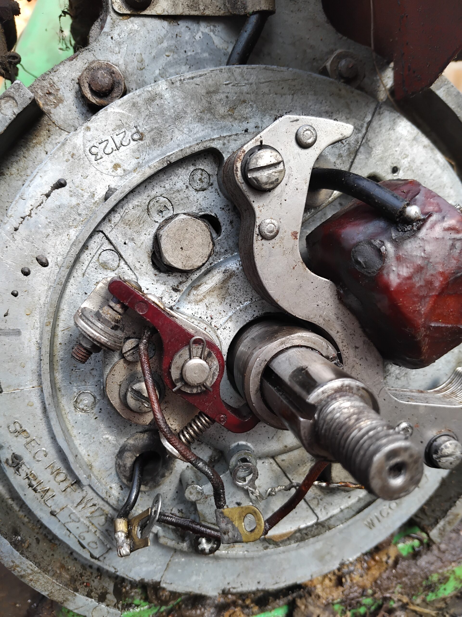
July 21, 2025 at 3:11 pm #43935ParticipantAndy In Grahame’s photo just visible I recon can see hole in the thread towards its end, I have seen all these sort of things bodges get up to, like a nut coming loose so they found one with a tighter thread being a different thread rate. Going back many years the one of the engines I had was a bit flat for some time but always started and checked the timing think 30 degrees BTDC if I remember right that didn’t improve things, then changed out the complete unit, only difference was the points, seems a bit odd as complete arm made of Tufnell used a flexi wire from coil and the stationary point was earth, whereas all the others have been opposite so stationary was insulated and fed from coil and point arm had just a fibre heal rest all steel earthed through the spring so less likely to fail, well it worked.
Attachments:
July 21, 2025 at 5:53 pm #43937ParticipantDavid , I’m not at all savvy with PCs , and haven’t yet fathomed how to blow-up photos , but the rollpin in his pics appears to me to be on the opposite end to the threaded part , but of course I could well be mistaken on that. Grahame states that he knocked the rollpin out , which to me would suggest that it went through the crankshaft , something I’ve never seen on the countless 2As that I’ve worked on.
Andy
July 21, 2025 at 9:44 pm #43939sidevalve5ParticipantIf using Windows on a PC, the default program will have a slider in the bottom right hand corner of the monitor with a – on the left, a + on the right. Move the slider to the right to zoom in. Alternatively, with the mouse cursor over the image, roll the mouse wheel up, away from your hand.
The roll pin is actually 3off, 2 larger ones and a centre spacer that is in the middle of the crank. Was going to not use them, but now am having second thoughts. After reading what David wrote, they could prevent the pulley pressing tightly on the flywheel because of a machining error on one of the associated parts. Rather than throw the batch away, fitting a roll pin was a more economic (bodge) solution. The ‘corrosion’ could be a type of loctite to prevent the flywheel moving in and out on the shaft. Am not sure about this. Going to grind the valves as I think this is the cause of the lack of compression, the seats look terrible because of years of storage with the valves open. When I re-assemble, will try to work out why the roll pins were fitted.
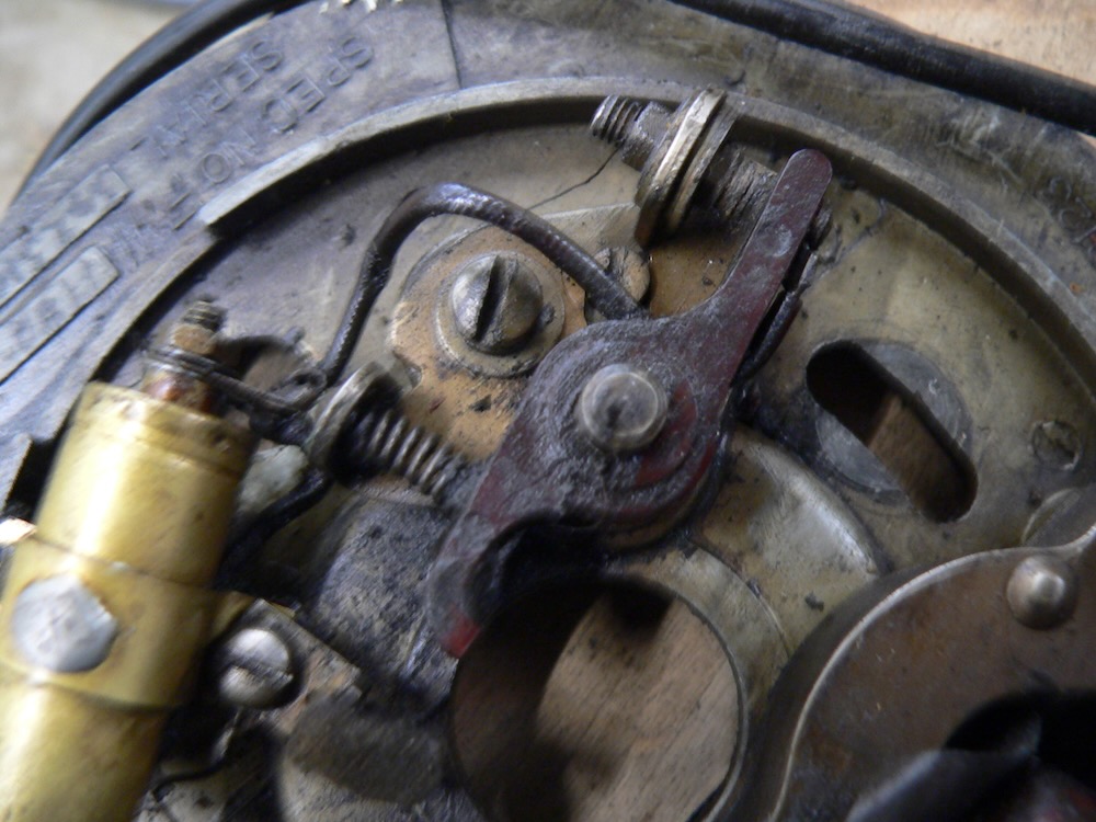
Have a 2a on a Colwood that I have had and used for 30+ years. The info I got all that time ago was the points gap is 0.018 – 0.020”, timing 30o BTDC. Have taken a picture of my points set-up and it looks the same as David’s. Believe mine has not had the cowl off since the day it left the factory, so it’s original. Can alter the timing by moving the armature backplate on the slots as shown in the photo. As the cam for the points is separate from the flywheel, can set the timing with the flywheel off. But expect it to be spot on as there is so little wear on the engine. Do not think it has done more than a few 10’s of hours since 1951.
Really pleased to hear Andy was approving of the external energy transfer coil trial. If it works, it should cost £25 max for the first one and £10 for the next 6 as the 125g roll of enamelled copper wire and a roll of heat resistant polyester tape will do several primary coil windings. Can get an external coil for under £6 if it purchased via Temu. It could save some old engines because it is so cheap to do.
Attachments:
July 21, 2025 at 11:35 pm #43941ParticipantGrahame , it would concern me when you said the pulley came of by hand , I can’t help but think all’s not right somewhere and would lead to flywheel/key/ crankshaft failure.All the 2As I’ve worked on the pulley tightens right up , and requires the impact gun to undo.
The points gap is usually stamped into the points inspection cover , I would hazard a guess that your engine has been “got at” at some point in its life.
I will admit to having little to no experience of the external transfer coil system , I only have one machine in my collection that uses it , a Honda F80(the twin cylinder upsidedown engine) , which starts and runs lovely , so thus far have let well done be alone.
Be sure to re-align the key with the cam , looks like yours has moved.Andy.
-
AuthorPosts
- You must be logged in to reply to this topic.
VHGMC Forums
Got a machine and need info or have a question? Then a post in the VHGMC forums is a great place to start!
Who's Online
There are no users currently online