Forum Replies Created
-
AuthorPosts
-
July 21, 2025 at 8:53 am #43929
 sidevalve5Participant
Andy,
I would agree that a 2A is a very simple engine to work on. Where we will diverge hugely is that because the flywheel was all but welded onto the crankshaft, it was a devil of a job to get it off. Your method would have failed in the first instance. Persisting in it would have damaged or broken associated parts.
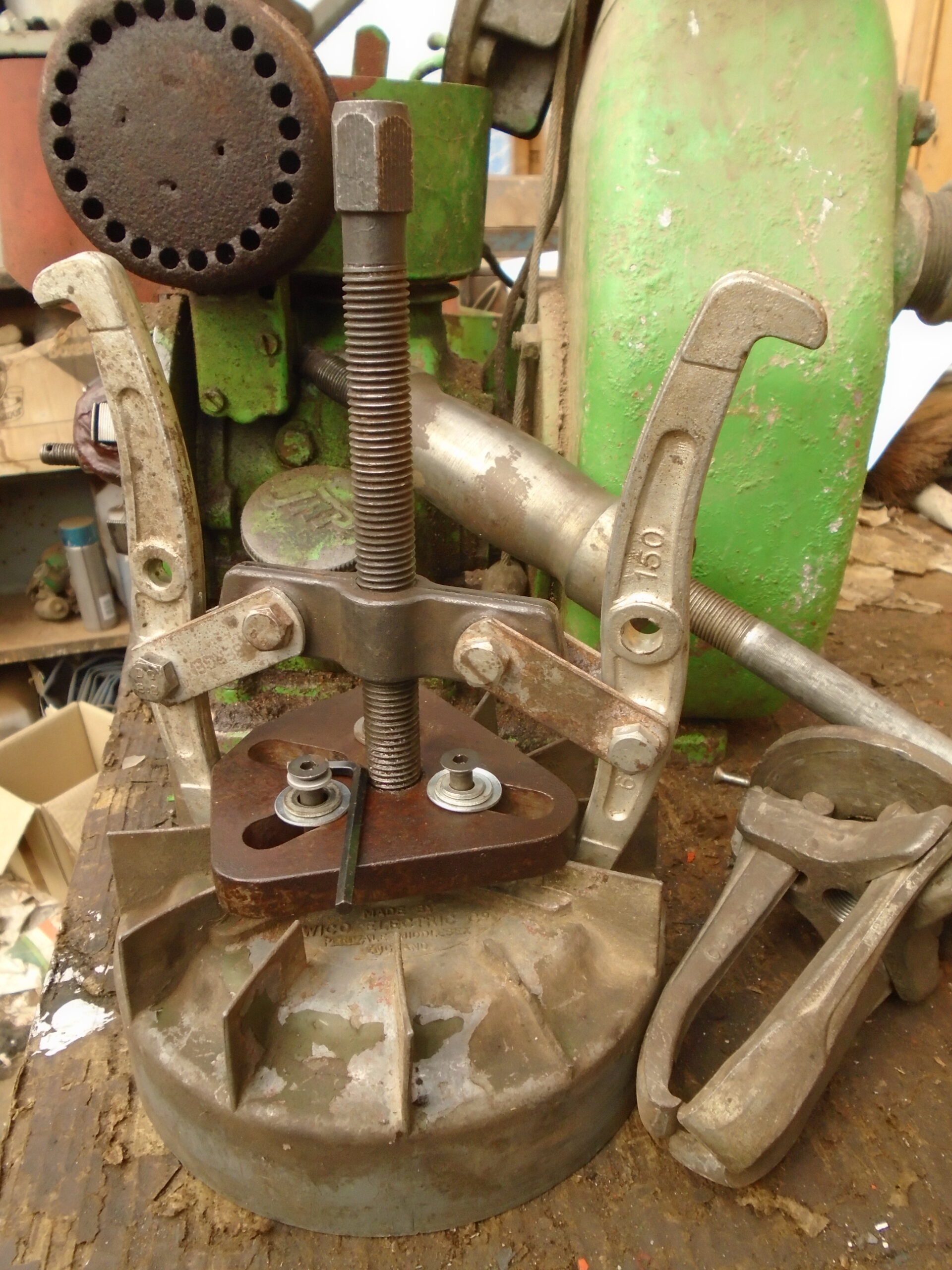
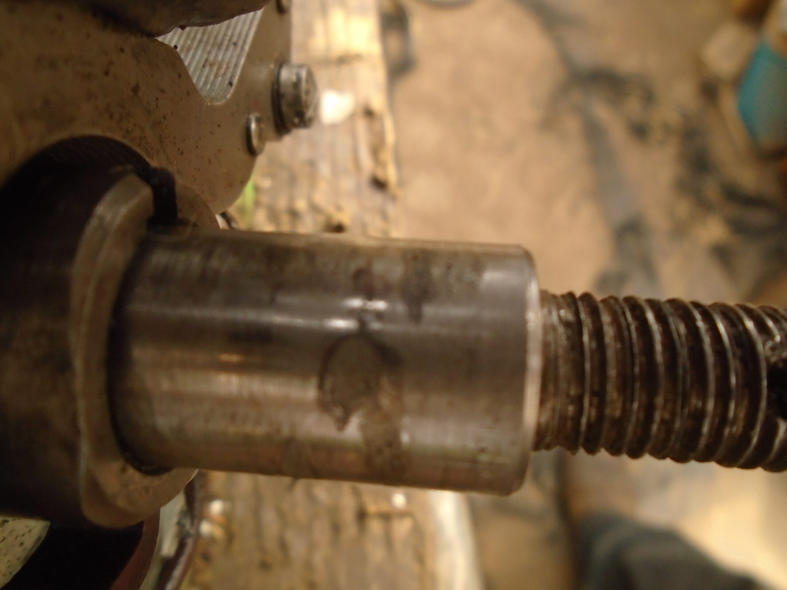
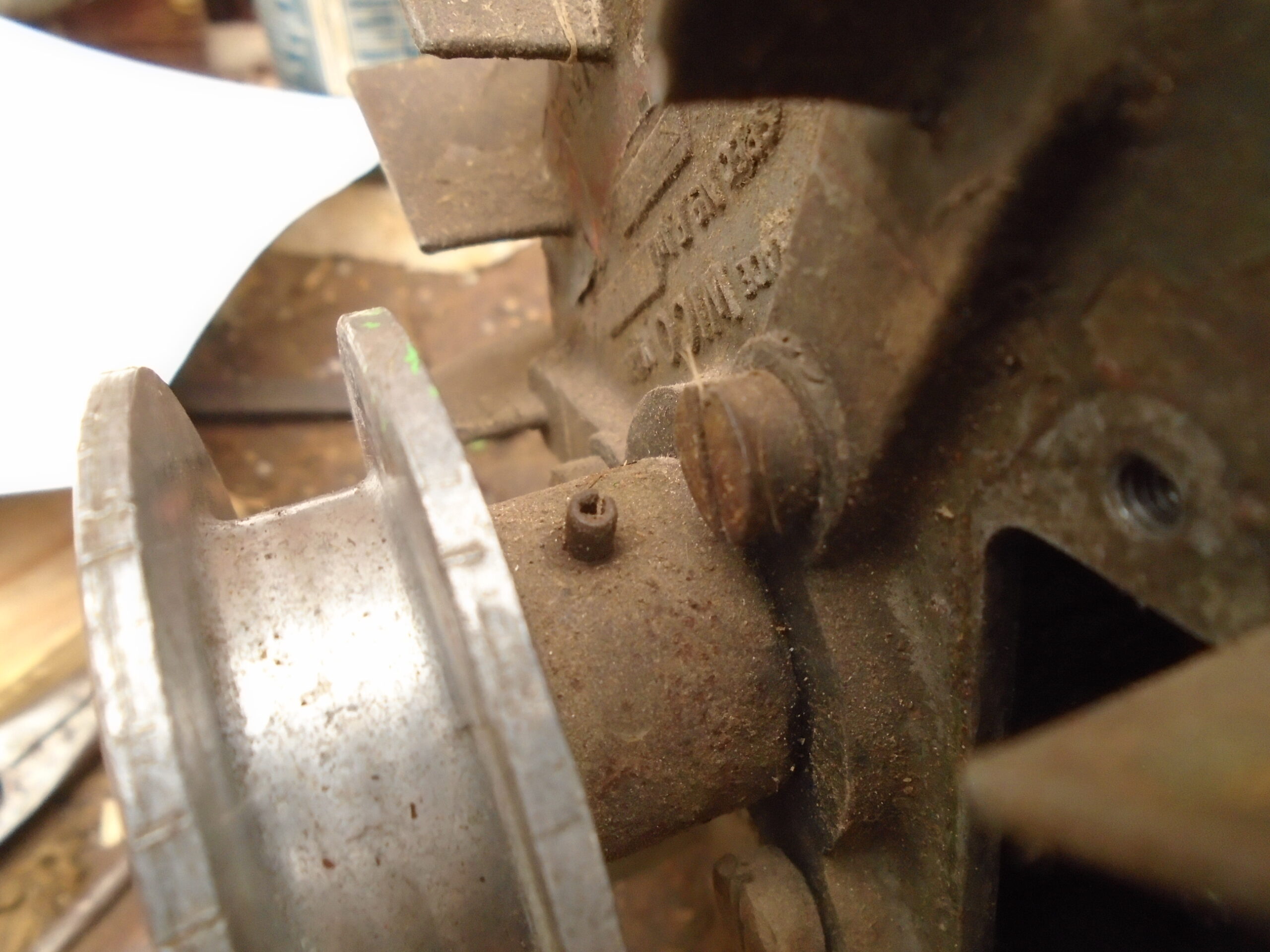
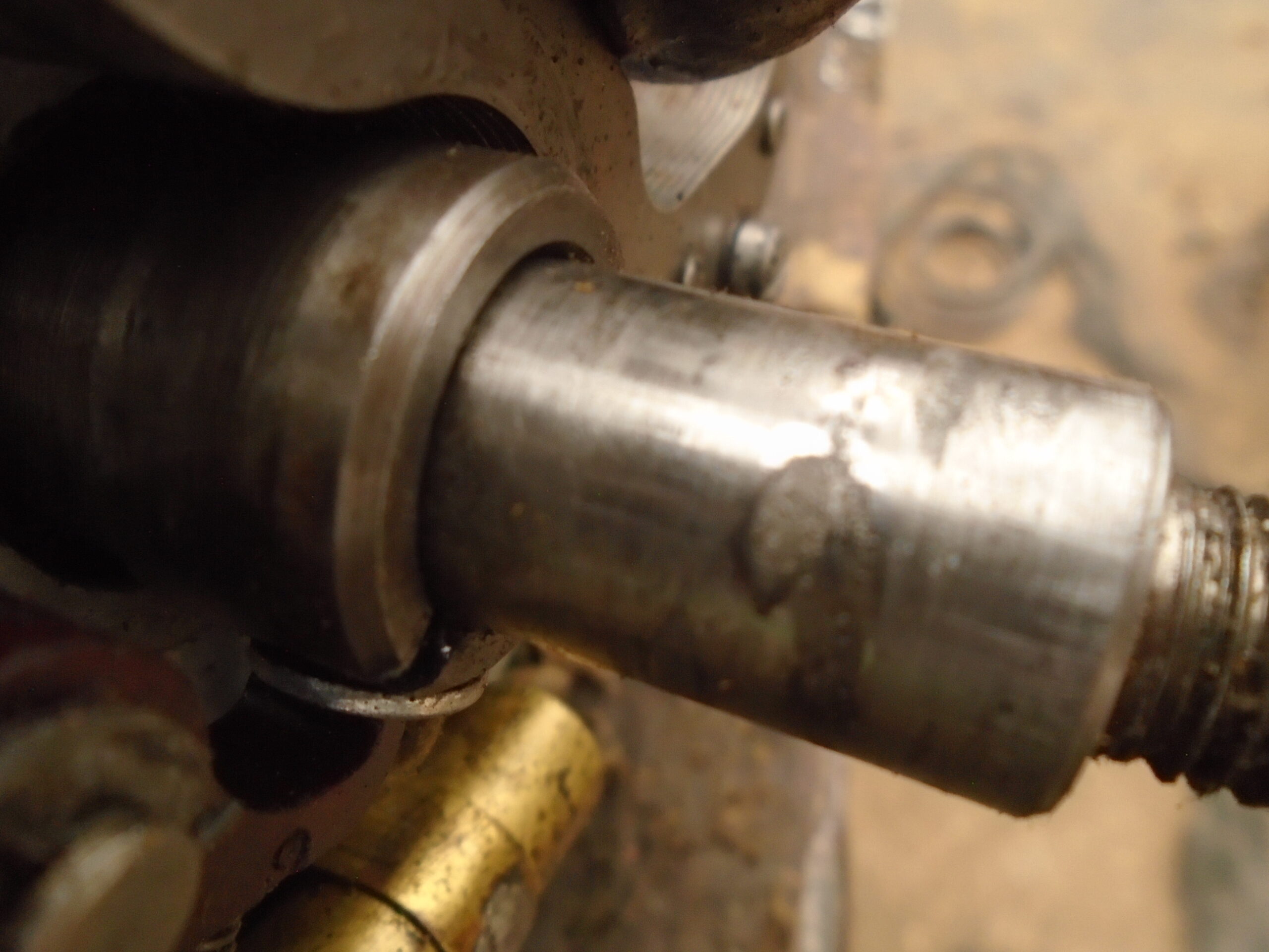
Attached are more images of the state of the shaft and the puller method I used, complicated you may say, but a necessity if the seized flywheel was to be pulled off the shaft. It consists of two pullers, one with the 4 hole attachment that I could fit the 3 whitworth bolts into. The bolts ideally needed to be longer, but this is all I could get hold off on a Saturday morning. Because the side hammer element would not fit as the crankshaft was too close to the centre hole. I got another puller to go on the attachment and placed 2 nuts in the middle hole to act as a centring spacer. It involved a 1/8 turn of the puller hex end, followed by several sharp blows on that end, for another 1/8 turn to be done and more blows. Repeating the process many times until it was free. You may describe it as complicated, I believe that I used care, skill, experience and a range of tools, applying them all in unison to do a difficult job.
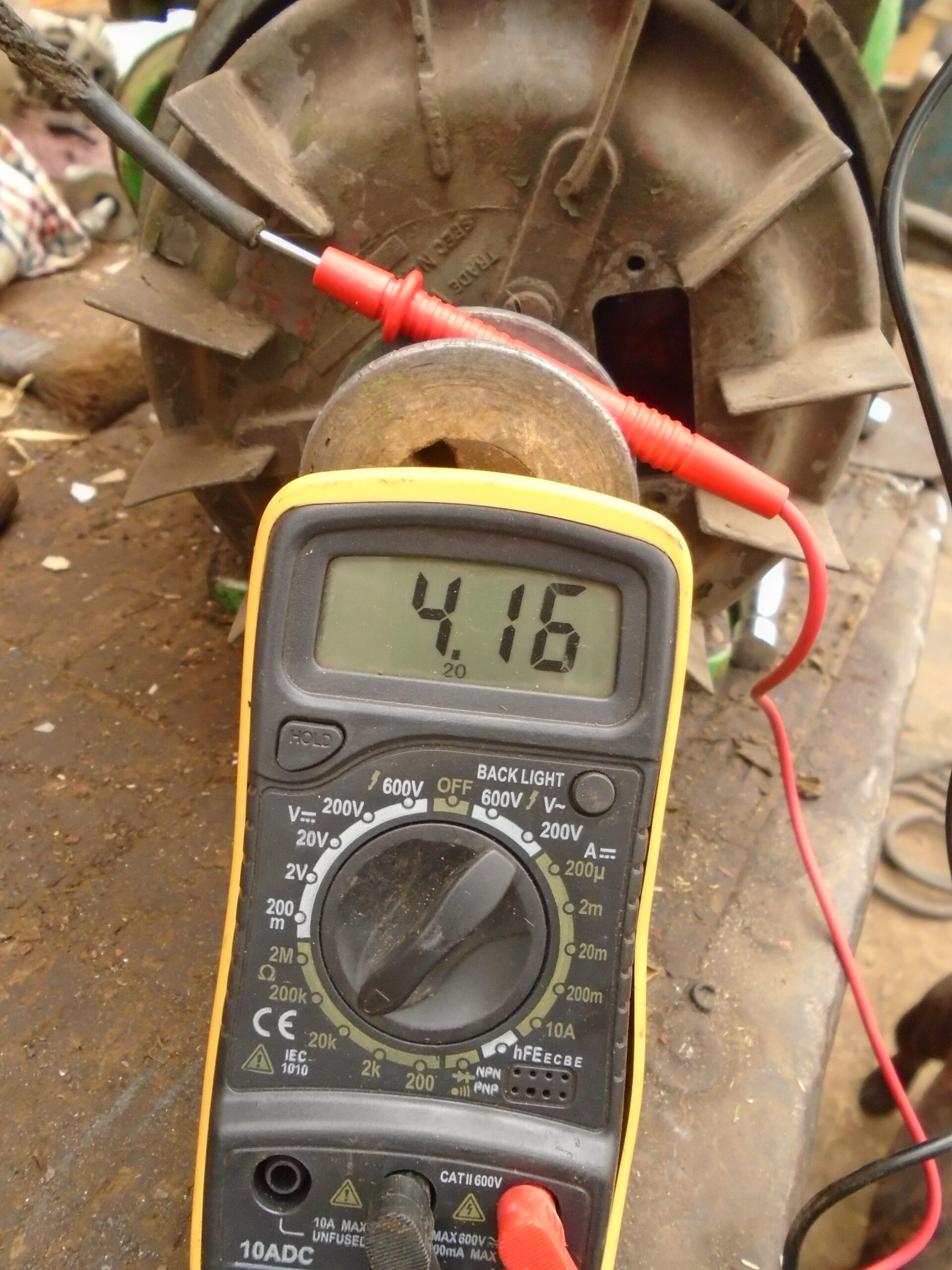
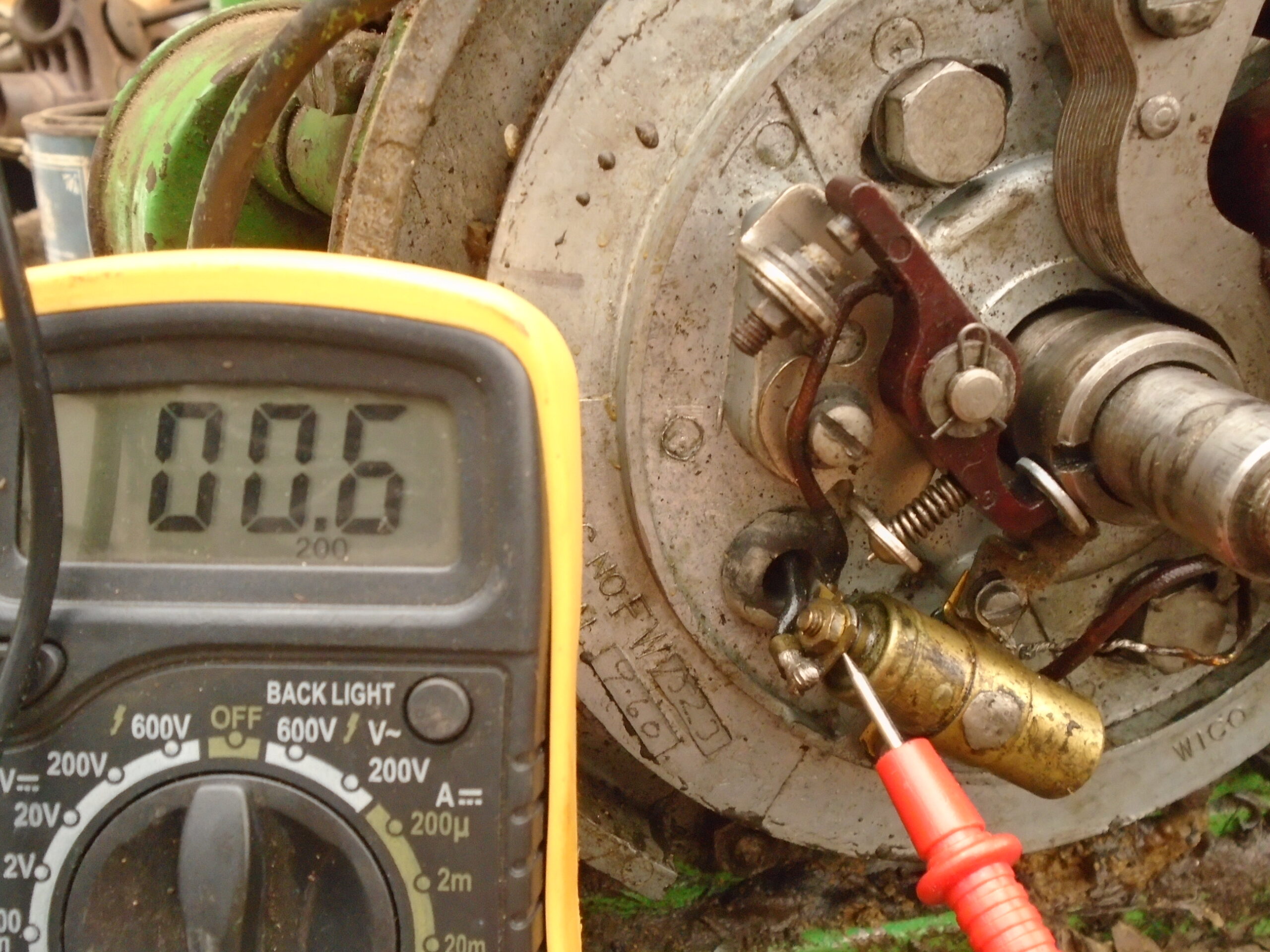
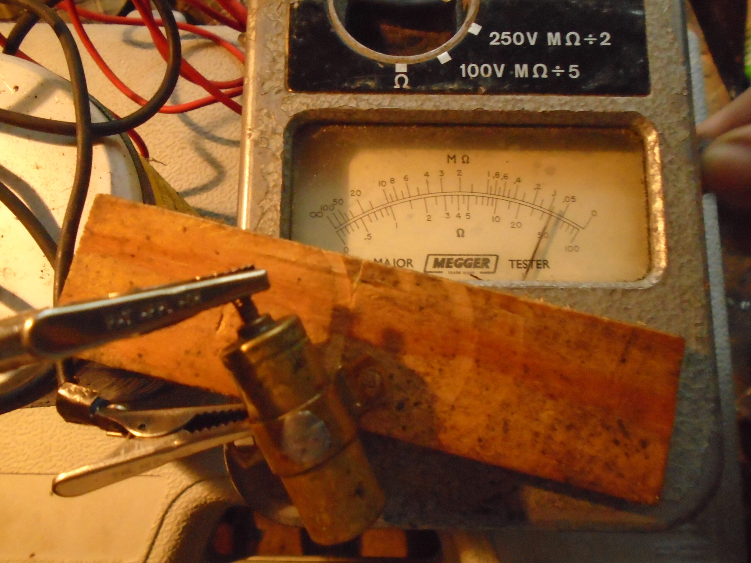
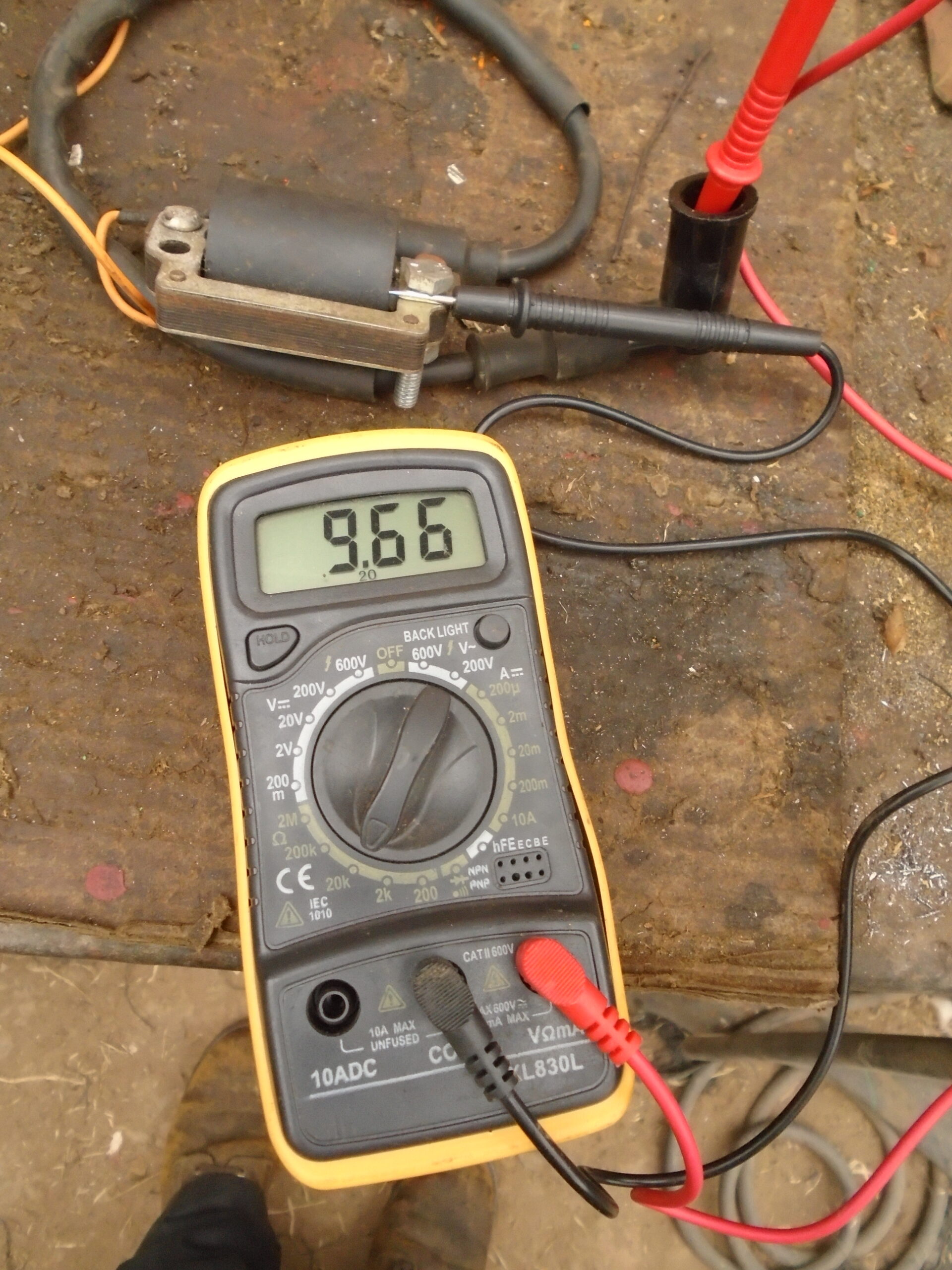
Again you may say my ignition testing technique that I have shown in the imagery is complicated. I would contend that it is a simple and quick diagnostic method of establishing where a magneto ignition trouble lay. In this case it was a 74 year old condenser with a wax paper dielectric, the primary and secondary coil windings are fine. Sending the ignition parts away to be tested, or just using the substitution method would have resulted in additional time and unnecessary expense in fixing the problem. FYI, testing took 4 minutes, the cost of the polyester film capacitor and board to mount it on is 45p, estimated time, 15 minutes.
You may say too that my intended fitting of an external coil is complex too. To my mind it is not, however I do concede a rudimentary understanding of mutual induction is required. Am not doing it to fix a failed coil, but to do an experiment to see if firstly, it actually works and secondly, if it does, is it better than a known good original system. I want to find out if winding a primary in my own workshop on a homemade jig and fitting an external coil is worth doing as opposed to purchasing an expensive new one. I could then advise others with greater confidence, as I would have completed the conversion myself. I also get great enjoyment and satisfaction from doing such projects.
Grahame
Attachments:
July 21, 2025 at 8:51 am #43928sidevalve5ParticipantJó látni, hogy mivel foglalkoztál, és várom a jövőbeli bejegyzéseket.
July 20, 2025 at 11:00 am #43923sidevalve5ParticipantHi Andy,
Please ignore the text in my last post. Am chatting to a chap in Australia who has done a 2A up and asked him about removing the flywheel too. I did the original text to him, them slightly edited it for you. Copied it to paste into the VHGMC forum box and for some reason (think because I had not saved the Word.doc before editing), although the one to you was showing in the box. When I posted it, the one to Baz went!!! No harm done though, just a little confusing. Yours is below:
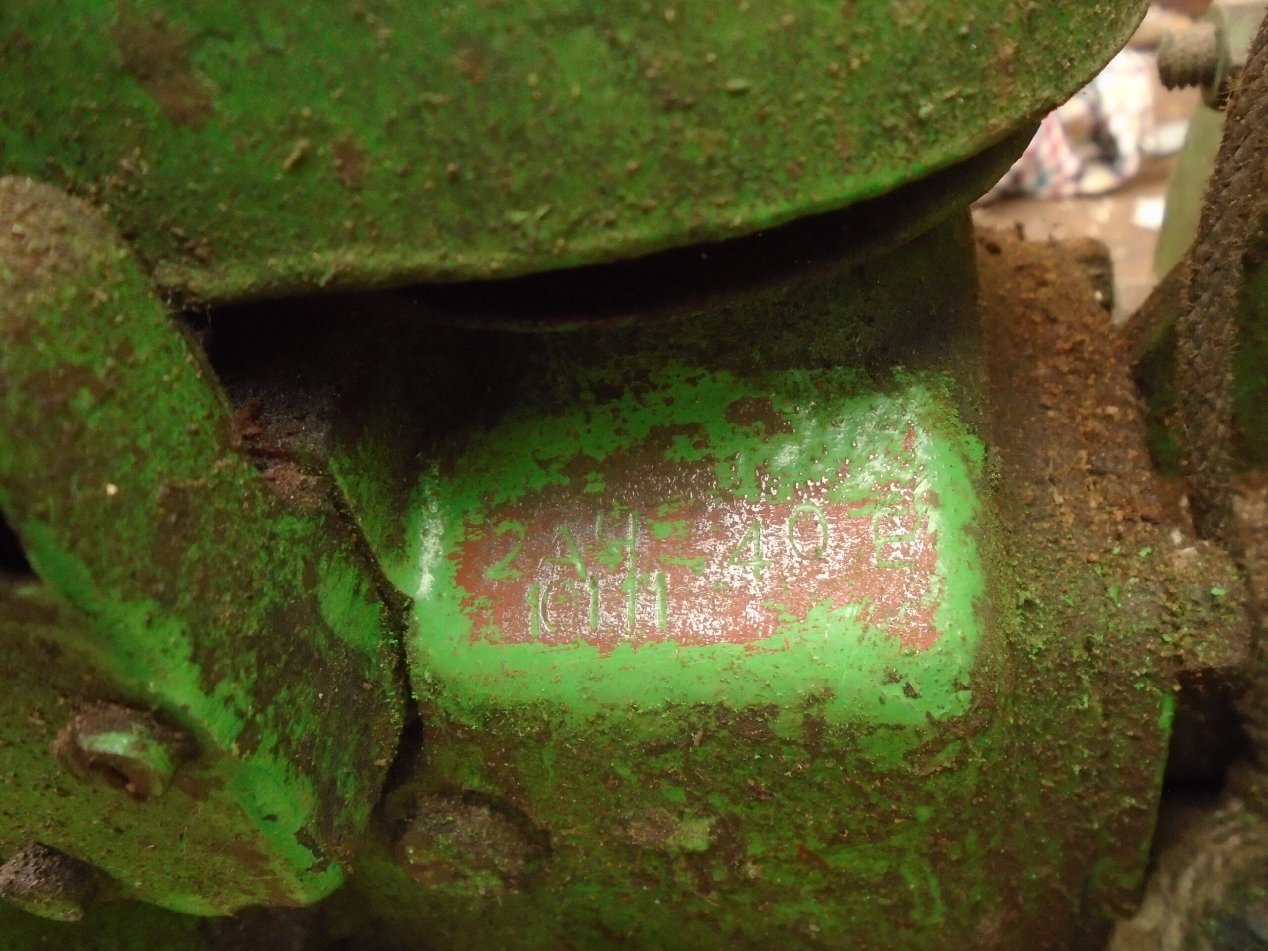
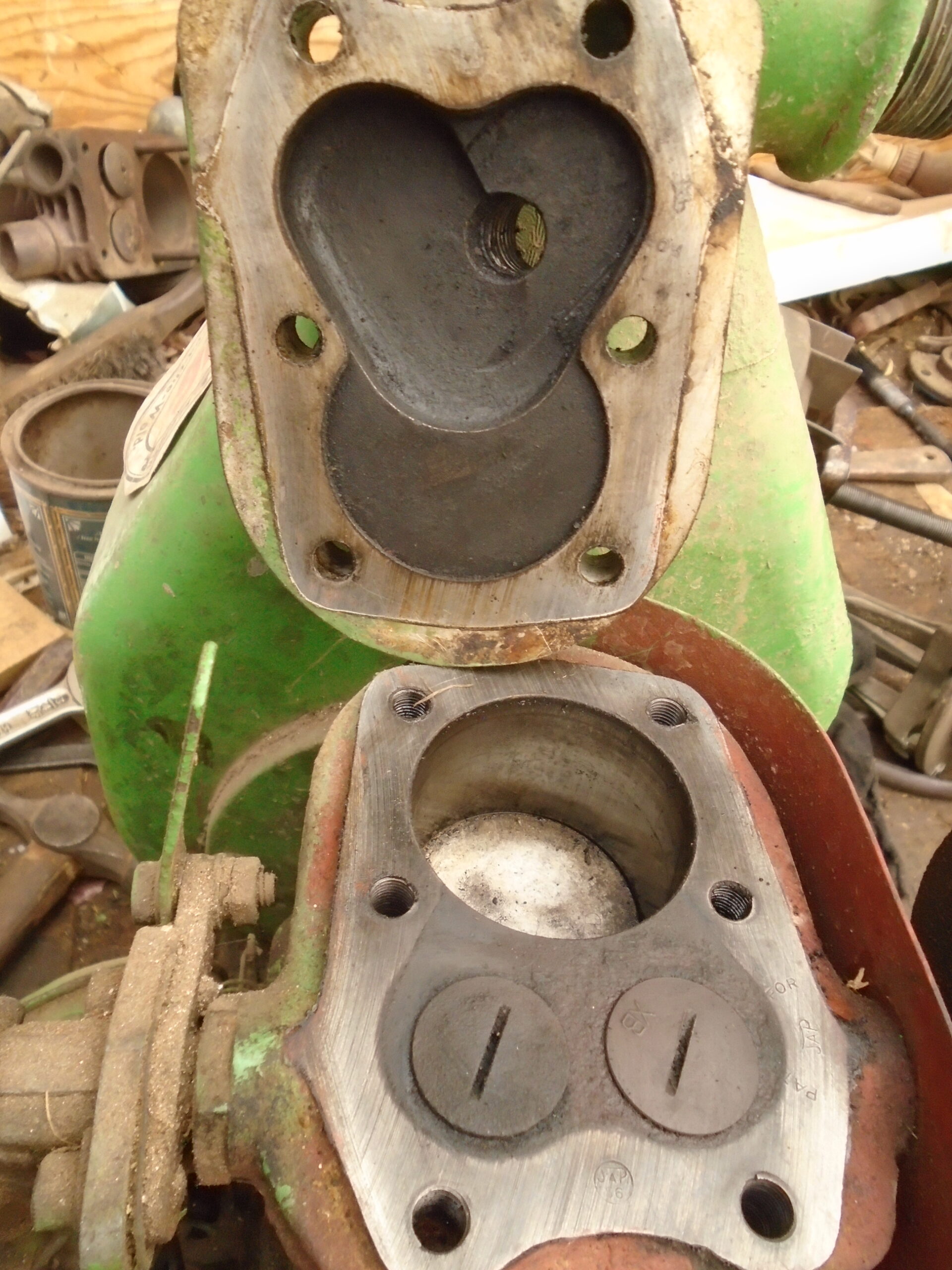
Got the flywheel off yesterday, had a right game with it. Believe the year of manufacture to be 1951 with the H (missing the bottom left leg) after 2A. Do not think the engine has done much work because there is no wear in the bore and what little carbon there was on the piston and head mostly wiped off with a rag. Took the head off, there was no gasket. Do you know if this is correct.
I do not think the cowl has ever come off because the bolt threads for the tank straps and carrying handle still had the lime green paint I think Alcon put on at their works. Believe Jap supplied the engine covered in red oxide as it is inside the cowl and some of the cylinder fins. Put a large socket in the bore and replaced the head so the engine was locked. Knocked of the three sections of the roll pin and the pulley undid by hand! Half undid the three set screws on the flywheel so I could get the legs of a side hammer puller underneath. No go, was worried about damaging the threads on the flywheel. Went to see a mate who had 2” long ¼” Whitworth bolts and put these in a four slots attachment I have for the puller. After a lot of effort, it came off and immediately saw the reason why it was on so tight. The surface of the shaft and the hole inside the flywheel seemed to show signs of a seizure, yet the shaft does not rotate inside the hole. I think either there was swarf or similar on/in it during assembly, or a machining flaw and if known, may explain the roll pin.
Initial continuity HT test showed a variable reading, think the black probe was not on a good ground. Have tested again yesterday, both HT and LT resistance is OK. Tested the condenser with a Megger, it failed. I do not use tradition condensers anymore, use a modern polyester film 630v 220nF/0.22uF capacitor. Was actually hoping the coil was duff so I could try again making up a single wire energy transfer coil system. Am still going to do it, but will take off the existing coil, make a former for a new coil, put the old one back on and complete the engine overhaul. Will test the spark from the existing system, then fit the internal coil I will have made and the external one. Then test that system to see if there is an improvement. Have attached the external coil I am going to use. All good fun.
Best wishes,
Grahame.
July 20, 2025 at 10:52 am #43914sidevalve5ParticipantHi Baz. Got the flywheel off yesterday, had a right game with it. Think Facebook only allow one photo in a reply to a post, so will send what I have in a succession of replies to illustrate the matters better. Believe the year of manufacture to be 1951 with the H (missing the bottom left leg) after 2A. Do not think the engine has done much work because there is no wear in the bore and what little carbon there was on the piston and head mostly wiped off with a rag. Took the head off, there was no gasket. Do you know if this is correct. I do not think the cowl has ever come off because the bolt threads for the tank straps and carrying handle still had the lime green paint I think Alcon put on at their works. Believe Jap supplied the engine covered in red oxide as it is inside the cowl and some of the cylinder fins. Put a large socket in the bore and replaced the head so the engine was locked. Knocked of the three sections of the roll pin and the pulley undid by hand! Half undid the three set screws on the flywheel so I could get the legs of a side hammer puller underneath. No go, was worried about damaging the threads on the flywheel. Went to see a mate who had 2” long ¼” Whitworth bolts and put these in a four slots attachment I have for the puller. After a lot of effort, it came off and immediately saw the reason why it was on so tight. The surface of the shaft and the hole inside the flywheel seemed to show signs of a seizure, yet the shaft does not rotate inside the hole. I think either there was swarf or similar on/in it during assembly, or a machining flaw and if known, may explain the roll pin. Initial continuity HT test showed a variable reading, think the black probe was not on a good ground. Have tested again yesterday, both HT and LT resistance is OK. Tested the condenser with a Megger, it failed. I do not use tradition condensers anymore, use a modern polyester film 630v 220nF/0.22uF capacitor. Was actually hoping the coil was duff so I could try again making up a single wire energy transfer coil system. Am still going to do it, but will take off the existing coil, make a former for a new coil, put the old one back on and complete the engine overhaul. Will test the spark from the existing system, then fit the internal coil I will have made and the external one. Then test that system to see if there is an improvement. Best wishes, Grahame.
Attachments:
July 16, 2025 at 10:02 am #43896sidevalve5ParticipantMany thanks Andy. Am going to have a go at taking the flywheel off at the weekend and will take a picture of the roll pin. It looks like there is a sleeve or spacer behind the pulley and the roll pin would lock it in place. The first numbers on the crankcase are 2AH, which I think means it’s a 2A manufactured in 1951. But the H is higher than the 2A and missing the bottom right leg of the font. Will take a picture of that too. Could you please confirm that the aluminium pulley will be attached to the slotted steel bolt. So all I have to do is lock the engine and undo the bolt. Have a Warrington hammer that fits perfectly inside the slot, so just need to keep it in really tight and turn. Have an attachment to a slide hammer puller that has 4 slots in it, so bolts at both 120 degrees and 180 degrees can fit. It was in the back of my mind I had something buried in a toolbox that would work and just found it yesterday after a rummage. Think in the first instance am going to try to use it as it is similar to JAP’s specialist puller. Did not know it was a straight shaft and key, was under the impression it was a taper shaft. Great to get that info too.
It looks like the engine was supplied to Alcon painted in red oxide and Alcon then covered everything in lime green. The inside of the cowling still has the red oxide paint on it. It does not look like it’s done much work and been kept in the dry, so will be a little surprised if the coil is duff. But until I get the flywheel off and test at the pickup, I will not know. Am actually not bothered if it is as I have been waiting to put an external single wire energy transfer coil onto such an engine. Know the theory, but have not put it into practice and this little JAP is an ideal candidate. Mocked up the coil I have yesterday and it will fit at the end of the fuel tank. Will keep you posted how I get on, but I will not be doing the full overhaul in one hit. Summer is the growing season when I use my machines, winter is tinkering time.
Best wishes and thanks again,
Grahame
Attachments:
July 15, 2025 at 10:18 am #43891sidevalve5ParticipantAgree that if the production of the paper copy of the magazine is the main driver for increasing the membership fees. Then the possibility of a two tier fee should be explored, with the higher amount being paid by those who still wish to get it through the letterbox. The lower sum for an online version that can be downloaded. A cost analysis needs to be carried out for a more informed decision.
Am concerned that a £30 fee may put off new members from joining and others that are less active, or interested, will not renew. There is a distinct possibility that a 25%, or even a 50% fee increase, will actually reduce revenue.
I wish to emphasize that I think the paper copy of the magazine is fantastic, those involved in publishing it rightly deserve great credit. But is the financial cost of printing and sending it to every member too heavy a burden on the budget. Should those who wish to either be happy to download the magazine, or thinking if the higher fee is worth it. Affectively subsidize those that insist on having their paper copy.
June 26, 2025 at 2:31 pm #43854sidevalve5ParticipantDid look at two stage as the optimum pressure required for the Hunter rotators was 40 psi. But had to factor in cost of the pump, cost of the extra fuel to obtain that pressure, the pressure exerted on the existing pipework and connections, would still have the slime problem blocking the filter. Can get second hand single stage petrol pumps for £30-£40, there is loads available, it’s just a matter a choosing the best one. When using hoses, especially layflat pipes, leaks at high pressures is an issue. The amount of slime I got, meant I had to clean the filter after just a couple of hours irrigation, which was a pain.
Went to a sale at a nursery a few years ago and they could not sell a couple of two stage vertical electric two stage irrigation pumps. I was tempted to put my hand up, could have got them both for a fiver, as I had an idea of doing similar to yourself. After the experience gained from fixing the petrol pumps, knew I could repair the pumps if they did not work by fitting a new seal. Could take the electric motor off and put a V belt drive from a petrol engine, gearing as required. What put me off was I also knew it would be much heavier than a portable pump. When irrigating, I transport the pump to the well in my van, when finished, take it away again, putting it back into store. Unfortunately anything that a man can lift, if not securely fixed or hidden away and might have some value, even just for scrap, gets nicked around here.
For me, a sprayline was the way to go. Had pumps in the shed I could use, low output requirements supposed the input (fuel) reduced too, lower pressure meant there are hardly any leaks, the larger nozzles do not block with slime, so could remove the filter. Additionally I like to see and use traditional market gardening equipment. I enjoy bringing what most view as scrap back into a good (near new if I can) working condition and then using it as it was intended. As stated, it’s horses for courses, high pressures and flow rates require the correct equipment. For me it’s a pump I can take out the back of my van each time, pump at 7GPM to only 12-15psi. A small lightweight single stage petrol pump delivering a modest head is ideal.
June 26, 2025 at 10:01 am #43852sidevalve5ParticipantMy pump saga has been an interesting one. My original irrigation system was a bit of a hotchpotch of bits and pieces I had picked up over the years that included the Villiers/Alcon pump. In 2011 I purchased the Hunter MP2000 Rotators and found straight away the Villiers pump would not supply enough pressure. It always took 3+ minutes to pull water up from a well and knew it was therefore not performing as it should. I dropped on the Honda/Clark pump, it was better (26m or 85ft max head), but still not really enough pressure. I revisited some of my early training in pump performance graphs, the pressure and flow rates required for differing irrigation systems. I then got a very secondhand Honda/Loncin thermoplastic pump that supplied near optimal pressure, nearly 35 psi. If fact this was better than that stated in the manufacturer’s performance graph. But did not like using it, the priming filler cap was small and fiddly, it had been left outside, nuts and bolts could not be undone without damage or breaking. The engine was thirsty and ran a bit rough, it really needed a good overhaul, but did not fancy the probable drilling out of snapped studs. The next year I came across a Robin/Koshin SEH-50X for peanuts, the pump is top of the range with a 30m or 100ft head. Knew if I took the pump off it and mated it with the new Honda engine, fitting a new seal too. I would have a brilliant as new bit of kit and that was what I used until 2021. To buy one new today would be £350-500. What I did not know was the Robin engine was a good one. So I mated that up to the Clark pump and put it away for use as a spare. The additional benefit was where both engine shafts showed evidence of wear at the position where the rotary part of the seal is meant to gain a fixed grip on the shaft. By swapping them over, it placed them in different positions. In other words, the seal gripped onto an unworn part of both shafts.
In 2021 I was given the Evenshower Oscillating Spraylines. I wanted to use it instead of the Hunter Rotators, because although I could get good pressure from the pump. Slime that formed in the over-ground supply pipe used to block up the filter in short order, reducing flow. Spraylines do not need the higher pressure offered by the Koshin pump, so used the Robin/Clark pump instead. It is less noisy and sips less fuel than the bigger GX160 Honda. Did some testing, this system requires a delivery of 7GPM at 12 – 15 psi. The label on the recently acquired 1½” Alcon pump states the maximum head is 66ft (28.5 psi), but do not have a performance graph. So do not know the pressure when the flow is 7GPM. But fully expect it to be fine as the flow rate is so low, especially after seeing David’s video with the impressive jet of water going into the pond and still maintaining 20 psi. I have not started the Villiers/Alcon unit since 2011. Am going to try to get the JAP 2a working and see if it pumps. If it does I shall then carry out suction vacuum and delivery pressure tests. As I will have the testing kit out, will do the same for the Villiers/Alcon.
Have checked my 2a pump set and there is a hole on the section of casting that goes from the engine to the pump body on the carburettor side next to the bottom casting web. So if any water gets past the seal will drain out and not get into the engine. But I think my pump is a bog standard one, whereas David’s may have been a special order. The Villiers/Alcon has this section of casting spaced off the crankcase and I recall water coming out of it before I replaced the seal. Have thought again about the Villiers/Alcon not achieving what seems to be the recognized reading of a minimum of 20 in-Hg on a vacuum test for single stage water pumps. As it only has a head of 66ft, it may correspondingly have a lower ability to lift. It will be interesting again to test the pump and make some comparisons with others now I have more experience with them. When I last did it 14 years ago I was more interested in getting enough pressure to operate the Hunter system.
Villiers/Alcon sets were the most common pumps used by small market gardeners around Evesham for their almost universal sprayline irrigation. Larger growers had bigger kit. Evenproducts were an Evesham company and still exist, but the old premises now exclusively manufacture corrugated round steel water tanks with butyl liners. They once did have a large irrigation department and may have sold Villiers/Alcon pumps that they would match to an irrigation system’s requirements. My father had a two cylinder Lister diesel engine permanently fixed in a pump house attached to a single stage centrifugal pump. It was fed from a reservoir which in turn was fed from a borehole that was put in the 1950’s and went down 70-90ft to water bearing limestone strata. It never stopped running, but could not supply enough water into the reservoir in 24 hours for the irrigation system to run at full capacity. The water needed to be carefully managed in dry periods. The diesel pump could supply enough water for two large rainguns or a big field scale sprinkler system. But on the smaller parcels of land away from the main holding, a small petrol pump pulled water from a well and fed spraylines. A big pump would drain the well too quickly, he had a Villiers/Alcon unit. The two wells I use on separate pieces of land contain 750 and 1250 gallons respectively and take 2 – 3 days to refill. A sprayline can be as much as 16off 15’ sections long and would require a supply of 800 gallons per hour. For a good soaking, it needs to run for at least 2½ hours, or 2000 gallons. It is horses for courses and where an understanding of supply capacity, pump performance graphs, flow rates, delivery pipe sizing, pressure requirements and precipitation rates is needed. Everything has to link up for a successful system. Most mobile petrol pumps are the single stage centrifugal type with a manufacturer’s maximum pressure ranging between 20 – 35 metres of head (29 – 50 psi) so can be used for a small irrigation system. Including an Alcon. As long as the flow rate does not reduce the pressure to below that what is required at the nozzles.
Where I was caught out was the Hunter specifications stated a 16’ radius at the minimum pressure of 25 psi. It never achieved this, it was more like 13’, the rotators got stuck, the water was not atomized correctly. At 30 psi performance was nearer to that specified, at 35 psi, even better. It’s why I tried multiple pumps. But not all was in vain, from memory each pump was about £30, the seals less and I have ended up with 3 good pumps, 4 if the Villiers seal is not leaking, 5 if the JAP works. More important to me, I have greatly enjoyed the journey.
Locally we have not had any proper rain since the end of February, so my wells and irrigation had been a lifeline too. The ground water levels have not dropped as I would have expected though, after refilling, the water in the wells is only about a foot lower than a ‘normal’ dry period!
Foot valves are used where there is an opportunity to eliminate manually priming the pump (filling it with water before starting) and often fitted to a semi or fully permanently fixed pump’s suction pipe. They keep water in the pipe, so there is little lag between starting and actual delivery. For mobile units where the suction hose is removed out of the water after each use, they do not have a purpose.
Most pumps used for horticulture have an internal flap valve as David has described. These prevent water from going out of the pump body when not in use, or when being primed before starting. When the pump starts with water in the body the action of the impeller within the volute creates a vacuum in the suction pipe and this ‘lifts’ water into the pump. It is when this process is going through it’s motion that the seal is under the greatest test. If air is sucked through the seal, or through the hose connection, the negative pressure of the vacuum is not sufficient to lift water by the amount required. So when a pump does not pump, or takes ages to start delivering water, firstly check all the connections on the suction side. If these are fine, then the seal is suspect. You can leave water in the pump between uses and not prime, relying on the flap valve to retain enough water in the body. From experience, this extends the time to takes to start delivering water. So I always top up the body anyway, unless it is used for stop/start operations within a working day. But after finding signs of corrosion on the steel engine shaft of each pump I have taken apart. I now ALWAYS drain them when I disconnect the hoses. Although I did this before because when I picked them up, water could slosh out from the flap valve, usually onto my leg, or in the van.
June 24, 2025 at 9:45 am #43833sidevalve5ParticipantHi David,
Fantastic video. The seal I took out of the Villiers/Alcon pump was all covered in crud and breaking up. Vulcan Seals asked if I could send it to them so a replacement could be identified and also they would have a record of it on their database. Just looked it up and it was in 2011 when I got the new seal. I cannot recall what the old seal’s construction method was. But they said the one I sent was probably a John Crane type from around the 1980’s, so not the original seal. The ungovened pump certainly revs away, a testament to the quality of JAP’s, which I think are better engines than Villiers. Believe this is from their heritage of high performance engines.
Noted the increase in pressure when you hooked up both pumps. When I tried it, it only raised the pressure by about 20%. What I did was pump from a more powerful Honda/Clark pump through the Villiers/Alcon set. The Villiers had a duff seal at the time and even if it would have been a good one. Think the difference in pump design and specification would have caused a degree of conflict within the system. It may have worked better if the Villiers pump supplied the Honda and that would have boosted the pressure more.
Vulcan Seals were very helpful in identifying a replacement seal for both the Alcon and Clark pumps. Leaks through the impeller shaft is very common, with wear damage and corrosion to the shaft being the problem. They have bellows type seals that help to overcome this and it is that what I fitted to the Alcon pump. But the corrosion over the length of the shaft I think meant it did not fully seal. I was going to get a stainless steel shaft repair sleeve to fix it. But it’s way down on my list of priorities because even if it performs as it should. It will still be not as good as more modern pumps. The Villiers engine is a good one, but is more thirsty and noisy than the Honda and Robin engines, the Alcon pump delivers a lower pressure. Did note that every pump I took apart had a degree of damage to the steel drive shaft. It was one of the reasons I swapped the engines over as the seals were then in contact with the shaft at a different position. If the stationary and rotary faces of the seal starts to create a lot of friction. It can partially seize and then the drive element will then start to turn on the shaft, causing damage, wear and finally a leak. It’s why a pump should never run with no water in it. Also pumping dirty water will wear the seal contact faces out quickly as well as scoring them. This roughens it and can lead to the surfaces gripping, again causing the seal to rotate on the shaft. An old boy who once installed irrigation systems for Evenproducts told me that even a tiny leak on the suction side significantly affects pump performance. It can cause cavitation and he has seen damage to the aluminium surfaces within a pump from it. Think some of the trouble with seals is also caused if there is a steel shaft that then rusts over time. The Villiers engine’s shaft was very pitted and although I sanded the rust off, think the amount of material removed and the still rough surface. Has enabled a small amount of air to get through. I do drain my pumps after each use, but when storing them now am going to blow them through as well. Great advice and thank you.
In summary, the Villiers/Alcon set had a well seized drain plug, I think water was left in it permanently, causing the engine shaft to rust. The Honda/Clark pump was brand new, got in case of flooding and started every couple of months, running dry. The sealing surfaces gripped, causing the seal drive to turn on the engine shaft. The Robin/Koshin (it was a Koshin SE-50X pump I got for the higher pressure, it’s was not a Honda pump as previously stated) was from a plant hire fleet and had a hard life with a strong possibility of being used for dirty water. The seal was very worn, with evidence of the drive element turning on the shaft. All of the above could have been prevented with better user understanding and care of the equipment. Hope my experiences will help others in the use of pumps. It’s all worked out very well for me because I purchased broken pumps cheap, repaired them at little cost and have some cracking kit now. Was enjoyable learning about them too. Makes me think I must have been soft in the head when I put my hand up at last week’s auction. It was in part because of your descriptions of your pumps was at the back of mind when there were no bidders. Seeing your video has given me impetus to get the new acquisition going again.
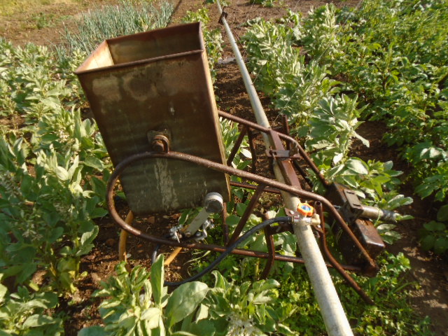
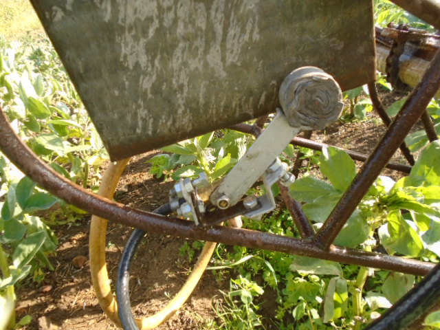
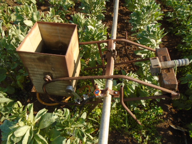
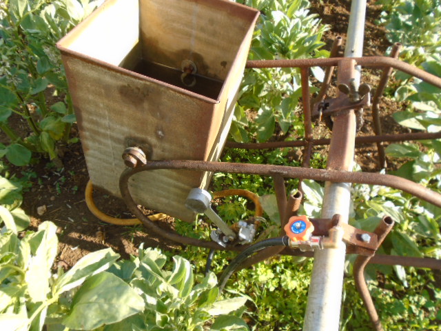
Did some watering yesterday evening and took some (not very good) pictures of the Evenproducts Oscillating Sprayline. In the Vale of Evesham when I was growing up most market gardeners had this setup. You do not see them now as traditional market gardening has died out. The oscillating system is really simple, with the tank filling from a nozzle and as it gets heaver it moves downwards against the effect of the counter-weight, twisting the sprayline (anti-clockwise in the photo). When the tank is near the ground the pendulum swings (to the left in the photo), the water from the nozzle is stopped by the 3 port valve and the water in the tank slowly drains out through the valve, the falling counter-weight twisting the sprayline in the opposite direction (clockwise in the photo). When to tank is nearly empty and raised up, the pendulum moves again, the tank starts to fill and the cycle starts over again. You can adjust flow rates and the pendulum stops for oscillation speed and irrigated width. The downsides are they are more labour intensive to move around, the irrigated area is small and precipitation rates low. None of this is a bother to me though, because it has upsides too. It is quiet, the application more even than sprinkers and they are better suited to pumping from a well with a limited volume.
Best wishes,
Grahame
Attachments:
June 23, 2025 at 9:44 am #43827sidevalve5ParticipantHi David,
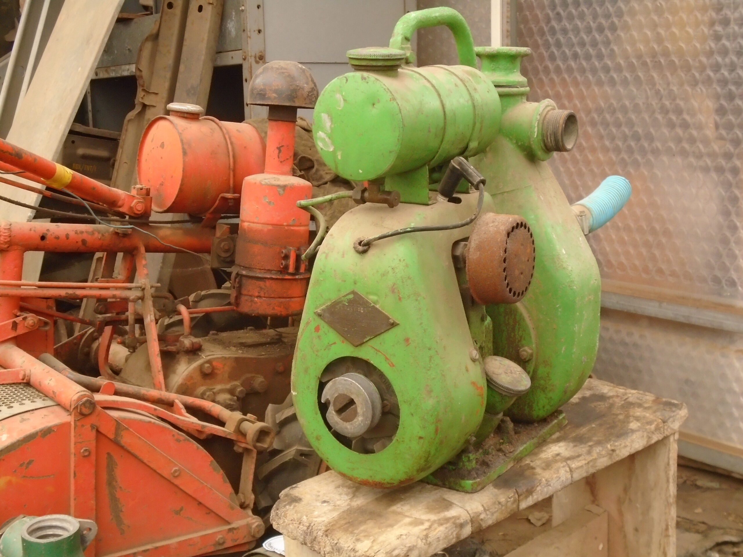
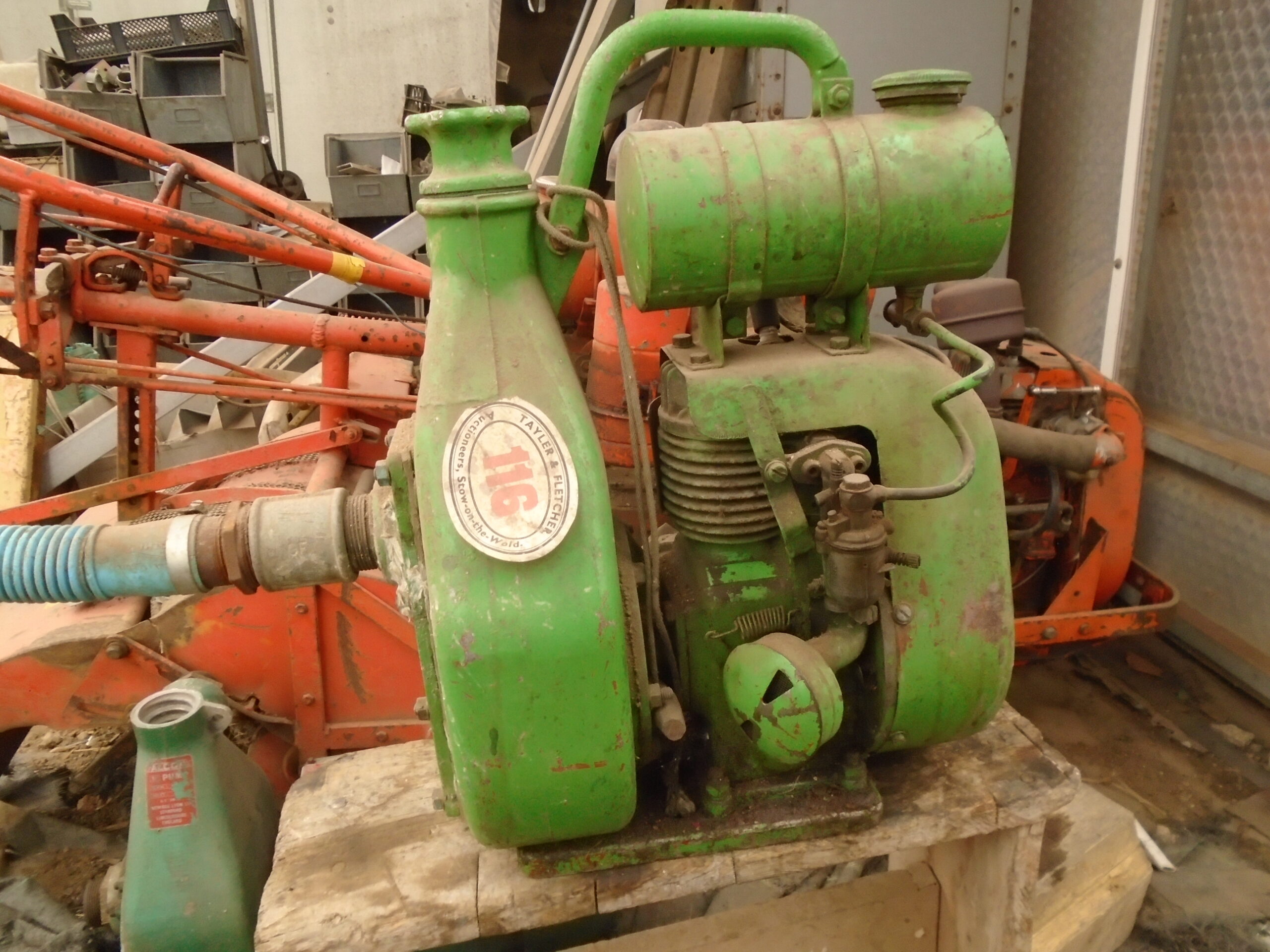
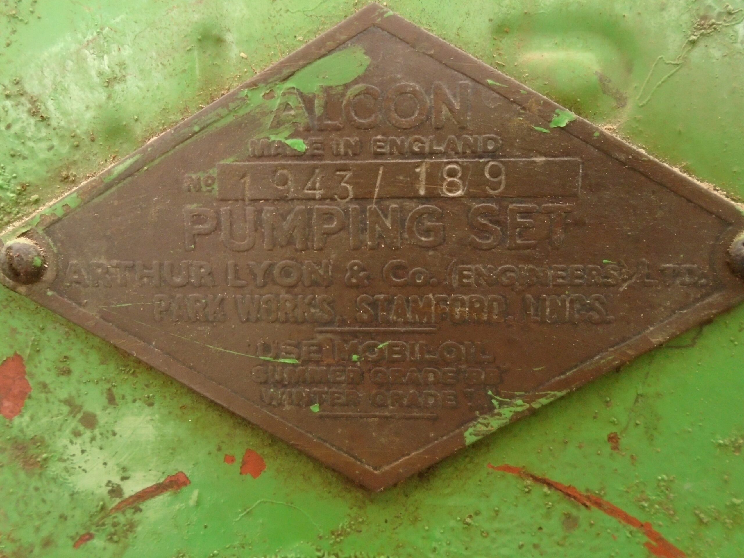
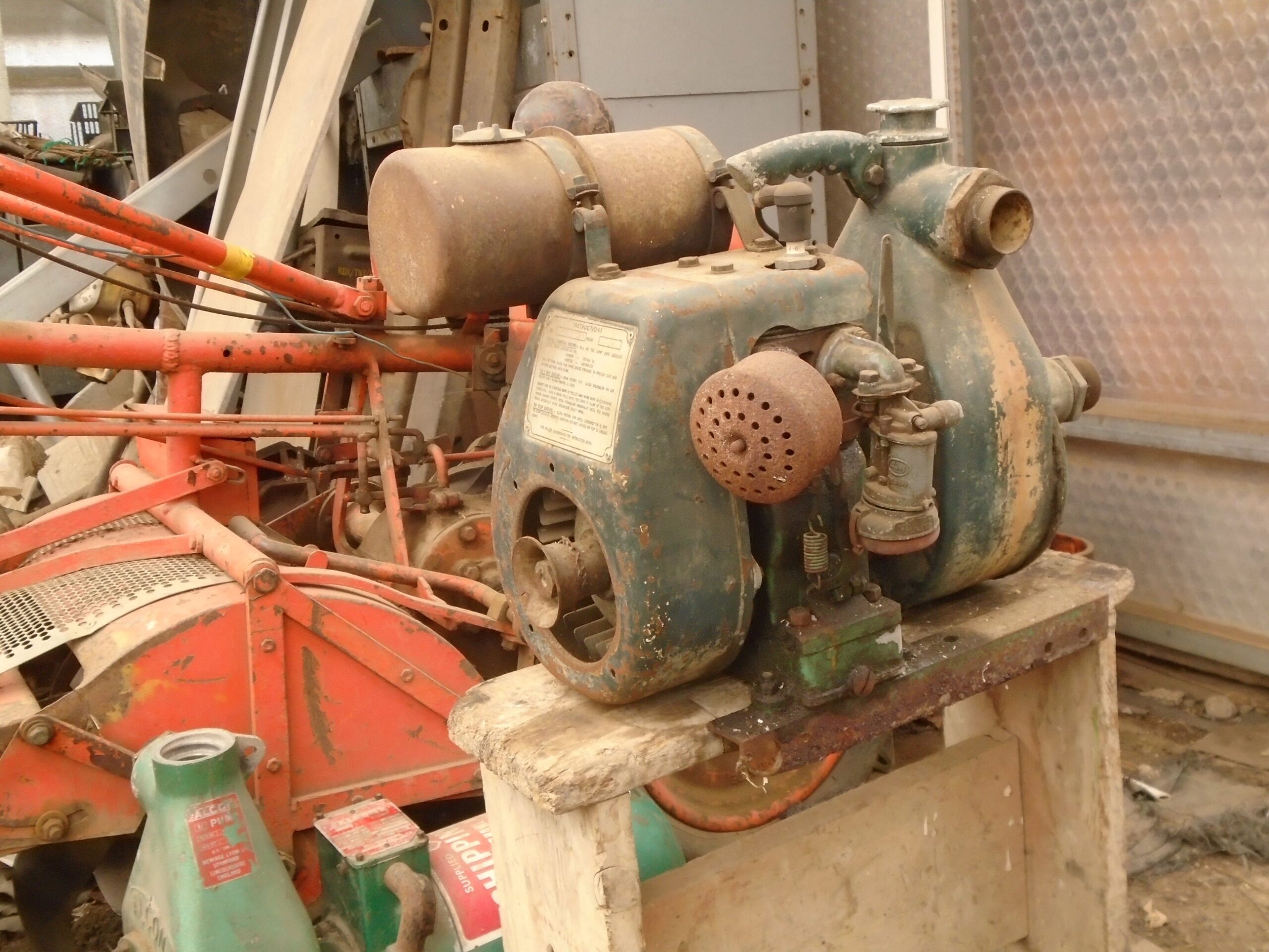
Took a couple of pictures of the one I got at the auction. Also my old original Villiers pump to add context. The JAP pump has a nameplate on the cowling with the first number being 1943. Do not know if that is the date it was put together, or if it is a coincidence. Also do not know if Alcon purchased the engines unpainted, then painted them all over in one colour. Or if it was reconditioned at some point and it was then it received the lime green finish. Be good it anyone could shed more light on this. The most important thing though is to get it working again and from the time it was painted, do not think it’s done much work. The oil is clean and the lot number shown is from a different auction. So it was likely purchased then, either the just stored, or the new owner could not get it to go until the farm clearance sale when I got it.
Had to do a bit of research about pumps when the Villiers engined Alcon pump would not provide enough pressure after I purchased 7off Hunter MP2000 Rotators to replace rotaframes. It would not both atomize the water sufficiently and throw it to the radius specified. I needed 25psi minimum, ideally 40psi, but 30psi would be OK at flow rates of 6.1, 7.7 or 6.7 gallons per minute respectively. Not many small petrol pumps could do that. But then got a Honda pump that just about did the job. During this research I discovered that you need a minimum negative pressure of 20 ins Hg (25” is optimal) on the suction side. Got a negative pressure gauge and did some testing and it was then I could determine if a seal needed replacing. Am afraid the Alcon pump never achieved the minimum negative suction pressure, even with a new seal. I also found that a new Clark 2” pump that had been run without water in it many times had ruined it’s seal too. A quick test is to put the palm of your hand over the suction end and it should have sufficient pull to feel quite painful. Or the time it takes to start pumping and if yours does this so quick, the seals are good. The Villiers pump used to take 3+ minutes.
If my Alcon pump was in good condition and could produce 66ft head, this would equate to 28psi with very little flow. Obviously pressure reduces as the flow rate increases. Another problem I had with the Rotators was blockages to the nozzles, so had to get a filter. Am pumping from a well into 80m of layflat tubing and found even tiny bits of debris (mainly little seeds and slime) caused troubles. Such a system really needs a permanently fixed suction pipe and underground delivery pipes. I then acquired an Evenshower Oscillating Sprayline system and upgraded it by doubling the nozzles to 10off on 6 sections and replacing the original worn out cone type 3 port valve to a ¼” BSP ball 3 port L valve. It works really well. It only needs 12 – 15psi at 7GPM. Believe it will run on a recently acquired 1” Locin pump, or a 1½” Alcon pump. But I now run it with the Clark 2” pump hooked up to a Robin EY15 engine and after it has started to delivery water from the well. Reduce the revs to about a third. It then purrs along under little stress. It’s a stress reliever for me too, I find watching, smelling and listening to an irrigation system operating therapeutic.
Best wishes,
Grahame
Attachments:
June 20, 2025 at 10:53 am #43816sidevalve5ParticipantAn update the Alcon 1½” pump. Went to an auction on Wednesday, there were two pumps there in one lot. One attached to a JAP 2a, the other to a 3 phase electric motor. The latter had an embossed ali label on it stating the pump had a head of 66’, so around 20m. This compares very poorly to even the cheapest Chinese modern equivalents if it is to be used for an irrigation system with even a medium pressure requirement. Am assuming the pump had a market for lower pressure irrigation systems and simple water transfer use with the smaller horsepower engines that were available.
The auctioneer had to drop the bid to £10 to get going, still no hands up until muggings put his up and won it. It’s worth it in scrap alone because of the heavy electric motor. But the JAP pump set is very tidy, as is the electric set up. The JAP set is painted lime green and was wondering if anyone has seen this colour before. Am not sure if it’s factory applied paint by Alcon, or someone has done it when it had a reconditioning. Both the Villiers engine pump and the electric one has the usual dark green paint that I have seen on other Alcon pumps. Whatever, it looks very clean, but without any compression. A stuck valve is suspected. Will have a play when I have some spare time and see if I can get it going.
June 10, 2025 at 9:19 am #43806sidevalve5ParticipantHi Ruben,
You may try this supplier https://howard-rotavator-spares.com/shop/ But I purchased an expensive clutch friction plate from them for a MkV Gem and the holes did not align with the drive plate. Got back to them, the reply was to tap the pins to fit as they were most probably bent. That was wrong, the pins were fine, it was the friction plate holes that were wrong. I managed to file them to fit, but not that happy about it. Communication and after sales service from them was poor.
Think your only other option is to try to get a complete, but non-running machine and use as a donor. Or get some of the parts made in Spain. Unfortunately not many sellers of such a machine would want the bother of arranging for it to be fitted on a pallet and transported to Spain. They come up sometimes in farm auctions and are quite cheap. They are occasionally on ebay uk, but often sellers there want silly money. The VHGMC magazine has them for sale too at times. But think in each case the transport problem will have to be overcome.
Best wishes,
Grahame
June 10, 2025 at 8:56 am #43805sidevalve5ParticipantHi Mark,
Glad I can assist and hope the testing identifies the problem. Am unfamiliar with the machine or engine, but from the photos it looks like it has a Kettering ignition system where the ignition is run from the battery. The black wire goes from the ‘hot’ side of the points to the coil. You can test this with the multimeter and for testing would not fit the cut out wire. But again can test it’s continuity with the multimeter.
The most common problems are dirt, or corrosion on the terminals of the LT side. A breakdown of the secondary windings in the coil, or a failed condenser. All easily and cheaply fixed on a Kettering system as the only expensive part would be the coil. If that has failed, you can substitute one from another manufacturer. It’s when they have failed in a magneto it becomes more costly.
Best of luck and please get back to me if you want any further information.
Grahame
June 9, 2025 at 10:23 am #43803sidevalve5ParticipantHi, below is my standard advice for ignition testing for those who want to try to fix a machine themselves:
If you have not done it already, firstly I would remove the points, hone any pitting out from the contact surfaces, refit and set the gap to 0.015”, also clean all terminal connections. With the plug cap removed, hold the end of the HT lead 6mm from a clean part of the engine and see if there is a spark. If there is, you have fixed it, if not, close the gap until its 4mm away. I find holding the HT lead steady difficult, so have got an adjustable spark gap tester that was <£4, its one of the best tools in my box. An engine will start and run with a 4mm gap, but for easier starting and smoother tickover, you really need the gap to be 6mm. A good mag will achieve this. <4mm and the mag needs attention and personally I am not happy until I get it to spark at 6mm. If still there is a poor or no spark, a test with a multimeter is as follows: for LT Continuity, rotate until the contact-breaker points are open. Set the dial to 200Ω, measure the resistance with the two probes shorted together. The reading will probably be a fraction of an ohm and note it. Then measure the resistance between ground and the ‘hot’ side of the contact-breaker. Deduct the noted reading from the reading on the dial and the result should be between 0.5 & 0.7 Ω. A high reading indicates a bad connection or break in the low-tension circuit. A lower reading means there is probably a short-circuit in the contact-breaker assembly or in the armature. For HT Continuity, set the dial to 20KΩ, place the red probe on the pick-up or HT lead, the black to ground, the reading should be between 3 & 7 KΩ. If significantly higher there is probably a break in the HT winding, or a bad connection between the winding and the pick-up. If significantly lower, its unusual, but still indicates a problem. A lot of ignition troubles are due to the condenser. If the LT and HT tests are fine and you have access to a megger, the condenser should pass a 2GΩ @ 500v test. If you cannot do such a test, I would replace it with either a recently manufactured one, not NOS and certainly not second hand. As the wax paper dielectric inside them deteriorates with age and use. Or get a modern capacitor such as an EasyCap CU220 from https://brightsparkmagnetos.com/ which is my preference. In my experience they often perform better than old style condensers. Have had instances where a good mag with the existing condenser achieved a spark at 4mm, by fitting a modern capacitor the gap increased to 6mm with the subsequent easier starting and a smoother tickover. Resting a plug on the side of an engine to see if there is a spark is not a good enough test if ignition problems are suspected.
What I do now is fit a polyester film 630v 220nF/0.22uF capacitors instead of a condensor. They are about £4 for 10 on ebay. I mount them on circuit board strip.
Grahame
June 9, 2025 at 10:10 am #43802sidevalve5ParticipantThis old dog leant a new trick. The problem with the Kohler ignition timing was twofold. Firstly, the manual’s instruction was incorrect. It stated that the points should start to open when the flywheel timing mark S was next to the armature plate mark and AFTER that, adjust the points gap to 0.020”. Yet this action altered the ignition timing. The correct method, which I found by reading posts on forums, was to set the gap and THEN adjust it so the points open at S. I originally followed the manual’s method and it resulted in the timing being too advanced by 8 degrees. The engine was difficult to start and in the end, impossible. The second problem was that I did my usual method of honing out pits on the point’s contact surfaces. This resulted in changing the timing and something I was not aware of. When I tried to adjust the points so they open on S, they did not open at all. The fix was to file some material off the heel that goes against the rod that opens the points. However I am going to get a new set of points as they are readily available.
The engine still did not start after the third pull, which is what I like them to do. It did get going in the end though and ran well. Am still not sure if it’s getting enough of the correct fuel/air mixture in the combustion chamber to start easily. Also it’s big heavy lump to pull over, the recent rebore meant it’s still a little tight, the starting handle position just below the handlebars is awkward and the belt clutch on the mower deck creates a lot of friction. All combine into me putting in a lot of effort and still having just one 4 stroke cycle which I hope will fire strongly enough to go to the next cycle. But at least I have a good runner now, the timing was the key and it was David’s original post that set me on course to fix it. It has also made me think that if an engine is mechanically good, the carb appears to function correctly and the spark is 6mm, but it is still a poor starter. Then the timing could be out and from now on am going to check this on ignition systems with points. From what I have read in the forums, wear on certain parts in old engines can effect the ignition timing. If I get this problem on what should be fixed timing and going to use the adjusting of the points gap as a method to getting it to the position the manufacturer’s recommend. Got to be careful the points still have a gap that is close to the recommendation too as otherwise the dwell angle may not be right.
-
AuthorPosts