Home › Forums › The Machinery Forums › Pedestrian operated machines › JAP 2a flywheel removal
- This topic has 31 replies, 4 voices, and was last updated 3 months, 3 weeks ago by
 charlie.
-
AuthorPosts
-
July 22, 2025 at 1:45 pm #43943
davidbliss
ParticipantGrahame, I have an idea what someone has done, the flywheel nut should be done up quite tight without the need of locktite, and with it being held in position with the roll pin and flywheel locktited sort of sends shivers down my back. and it could be penny has dropped. Right the crankshaft should be pulled up tight against that mag sides bearing, So it should be crank inner face up against, bearing, spacer, points cam and then flywheel all locked up tight with the nut, so you should have four parts to fit flywheel side yours wasn’t pulled up tight hence roll pin. I think what some would say is a non mechanical person has attacked or lost a bit it could even be on the impeller side loosing some shims that adjust clearance on the back side. Now if the flywheel wasn’t on at that time being messed with at the pump side they would have drawn the crankshaft threw some bit, then it looks to me they then fitted the flywheel later and on what should have been able to do is pull the nut up tight but in-doing so would have pulled the crank threw locking the impeller up against the back face, So I would remove pump housing and unscrew the impeller. Sort out the flywheel and hopefully be able to pull up tight and still turn the flywheel someone has lost something.
July 22, 2025 at 3:17 pm #43944 sidevalve5Participant
Am thinking very much along the same lines. The pulley should be done up tight against the flywheel, the roll pin prevents that. There is a strong possibility that if it is pulled tight it will pull the crank slightly towards the flywheel end. Am going to grind in the valves, so the stator plate has to come off. Will also get the deposits in the flywheel hole and shaft flattened off so I can get near to H7 h6 or js6 in the Limits and Fits tables. Should then be able to put the flywheel on and off relatively easily and see where the problem lies. Can try it with the roll pin and without, tightening the pulley. I think this is a factory bodge and if so, it was done for a reason. It could have also been a method to prevent over-tightening by ham-fisted ‘mechanics’ after the matter was raised. It could have been only done for a small production run, then decided to drop the idea. All I do know is that I do not want to damage an engine that has done little work from new.
July 22, 2025 at 3:31 pm #43946andyfrost
ParticipantH7 h6 or js6 , forgive my ignorance , but what exactly does that mean.
Andy.
July 22, 2025 at 4:11 pm #43947ParticipantGrahame , one more question , and it may sound off topic , when you removed the flywheel , was the large thick felt seal present around the stator plate.
Andy.
July 23, 2025 at 8:41 am #43950sidevalve5ParticipantH7 is a transition fit, where it’s not a sliding fit, but not a press fit either. The flywheel should fit over the shaft and come off again with very little effort. But have some resistance to rotational turning.
There was no felt seal around the edge of the stator plate.
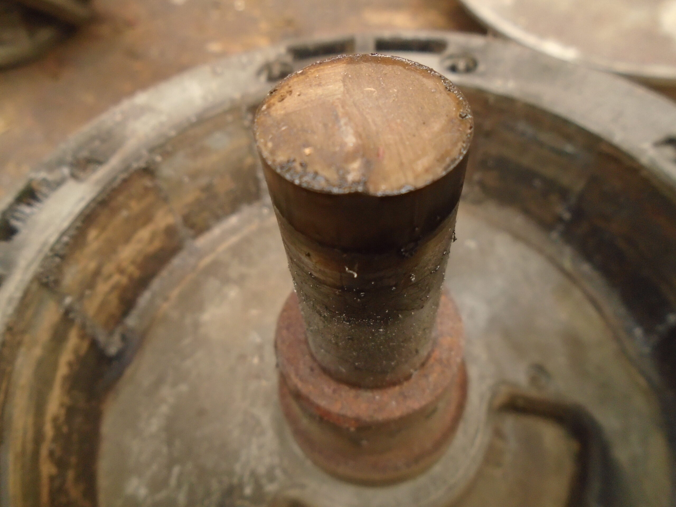
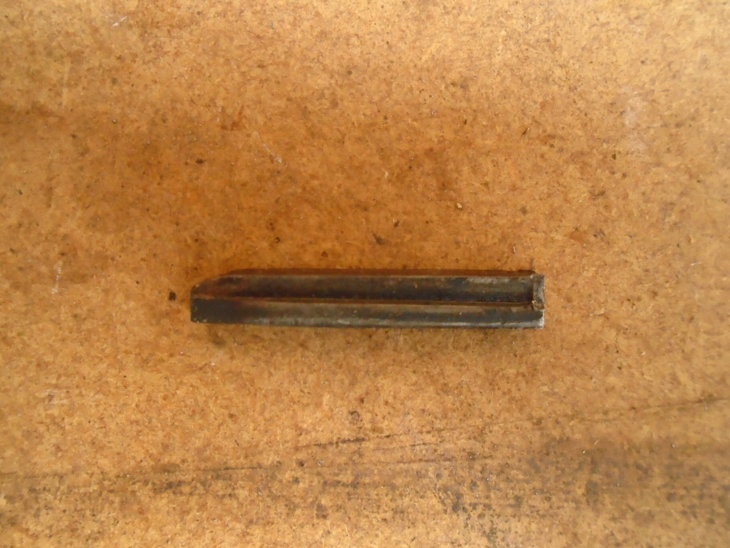
Believe the engine cowl has never come off since it left the Alcon works. So anything that is unusual was done by the JAP factory or possibly Alcon. The steel key has two grooves either side of it, so was designed to shear if the engine stopped suddenly. Modern engines have an alloy key that does the same. Have you or David seen keys like that on a 2a before, because I have not. Could be that the roll pin mod was specified by Alcon, but only for a short while. If the pulley was tight against the flywheel, the key would not shear as designed. Will take photos of the key and the sheared Villiers crank that I have mentioned in a previous post. That was broken by a pump sucking up a stone.
July 23, 2025 at 8:55 am #43951ParticipantI’ll have to wait for an accurate close-up of the key before passing judgement. No felt seal present is a further indicator that your engine has been apart before and been tampered with.
Andy.
July 24, 2025 at 12:18 pm #43954ParticipantGrahame, I would restore to original spec so wouldn’t cause other issues, not a modern? bodge up of an idea, flywheel, locktite and fail safe? key with a nut locked with a roll pin as couldn’t see that saving damage as with speed comes inertia. crank with its assisted flywheel with locktite and safety shear key don’t think parts would survive. I have restored the odd bit mechanical machinery that had been bodged or with parts missing and extras added on, then doing research often doing hundreds of miles going to museums, even then only to find there exhibits often had been got at with later parts added. I remember a commentator saying how wonderful an old car sounded on climbing a steep test hill with its chuffing of its engine, clouds of steam and orchestral whine of gears. Thank goodness things have changed over the years and now see some wonderful engineering in making parts putting them back to how they should be. A few years ago had a 1920’s Humber car gear box to check to find out to what had caused it to get stuck in one gear. Well it was simple, no way can keys in keyways that drive sliding gears can be held captive with rivets for long, they eventually break so why put them in when the key’s can’t escape anyway as two sets of gear hold them in. So a easy fix get rid of rivets. I was told this car was so original and never been touched, with all having the lovely sounding noisy boxes. So I was looking at the gear profile that was good but heavily worn, shafts and gears didn’t match so a mixture of parts, bearing caps chewed up showed of previous disasters of bearing failure so the boxes past showed it was Knackered. New keys, bearings and to prove a point those boxes should run quiet was able to press off both of the meshing second gear ratio’s turn over and replace so they ran silent on drive but noisy on overrun. I was soon asked could I do it to the other gears.
July 24, 2025 at 2:17 pm #43955ParticipantDavid , you’re correct, by Grahames admission the flywheel nut was only “hand tight” if it had been run like that it would not have lasted , the key would have shattered , resulting in untold damage very quickly indeed. JAP2A keys were never meant to shear , a steel key on a steel shaft in in steel housing is so obviously a recipe for disaster if your only hand tightening
Simply reassemble how it should be , tighten right up and as the saying goes it’s job done.Andy.
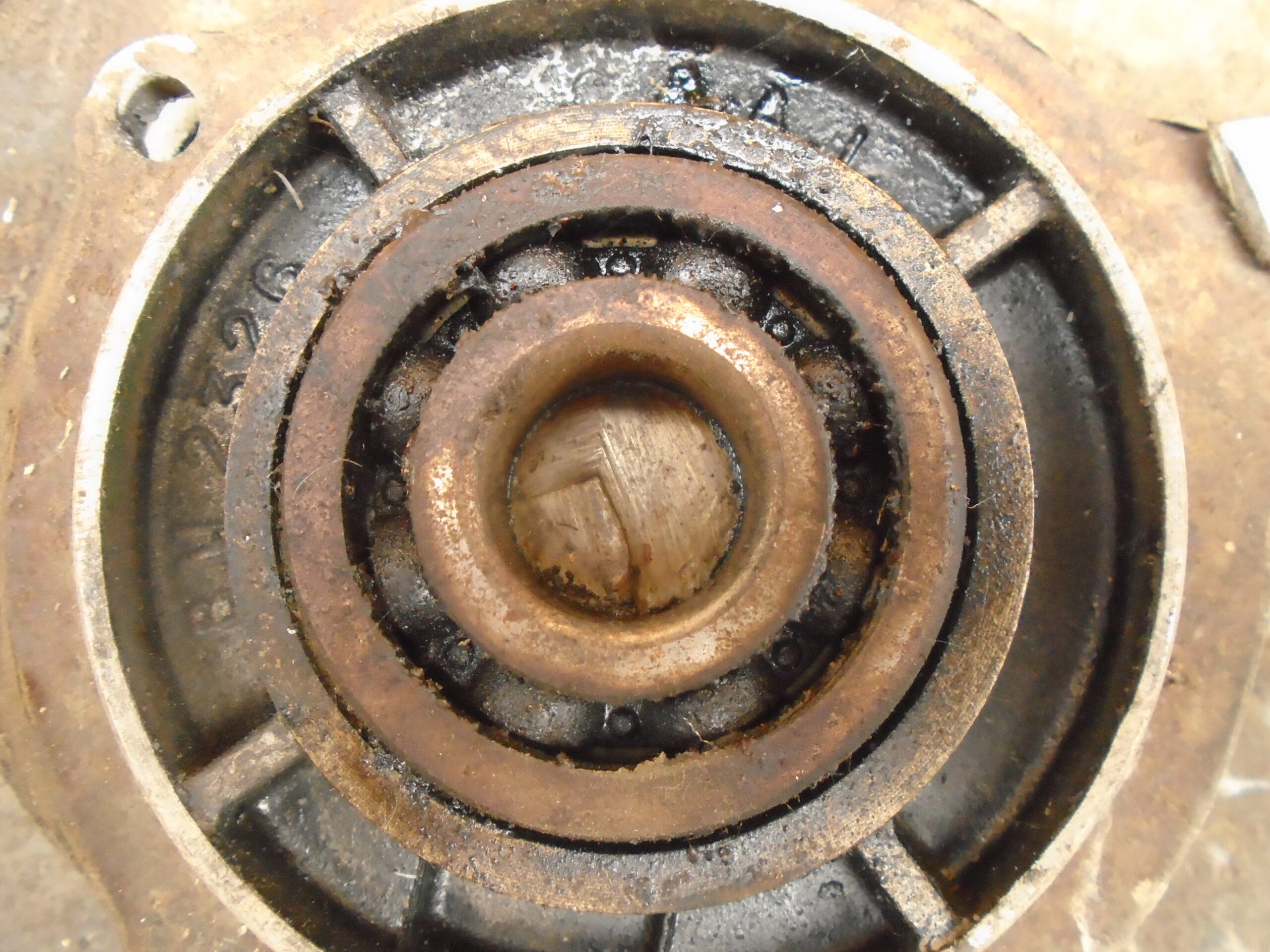
July 31, 2025 at 10:19 am #43963sidevalve5ParticipantHere are the photos of the sheared Villiers pump crank after a stone came through the suction hose and locked the impeller. Also the 2a grooved key and a cropped image of the bolt threads showing the original paint on them.
The clean cut on the crank vividly demonstrates what can happen when an engine suddenly stops stone (pun intended) dead and the energy created by momentum of the reciprocating parts has nowhere else to go.
Once got a mixer for it’s drum, my old one had started to rust through. The mixer had a Briggs & Stratton engine that would fire, but not run. Was not bothered, as I had a rescued Honda to fit on. But when I had 5 mins free thought I would get the B&S going. But no go, I subsequently revisited it a couple of times, could not understand why a nearly new engine with good compression, a big fat spark and fuel would only pop and bang for a minute or so. Decided to take off the flywheel to check the ignition timing and the alloy key had half sheared. The drum had stopped suddenly, the flywheel still was able to move and it probably saved the engine. It now runs as sweet as a nut, but have it stored away with no use for it. Have been told to always fit a genuine B&S alloy key, never a steel one.
Have a Clifford Mk1with a Villiers 25c. I re-fitted the flywheel using only light taps on the T bar of the socket and glad I did. When using it I hit a stone that stopped the engine and moved the flywheel on it’s taper. Otherwise the 25c crank could have sheared. My Howard Gem has a pin in the shaft from the clutch that is there to shear if the rotors stop suddenly. Some plough and cultivators have shear bolts too to protect the implement. The grooved key and roll pin follow the same principle.
The paint of the threads should put to bed any thoughts that this engine had had it’s cowl off (and by extension the flywheel), since the day it left the Alcon works in 1951/2. A further inspection revealed the felt behind the stator plate, although I fail to see the relevance of it. The roll pin and grooved key are factory modifications most likely done at the JAP works in conjunction with Alcon. It could be a one off, or part of a small batch, who knows. The grooved key is designed to shear and the roll pin that prevents the pulley from being tightened hard against the flywheel, will let it turn if the engine stops dead. Better a sheared key than a sheared crank. On a portable pump used by ill informed operatives, a solid steel key I would describe as a “recipe for disaster” a sheared crank “untold damage”. The roll pin only has to resist against it’s own rotational inertia force whist the engine is running and the action of the starter rope from static. Not much. It’s primary purpose is to prevent the pulley going tight against the flywheel, so it is free to turn if the key shears.
This will be my last post on this subject (JAP 2a flywheel removal) until I have got the engine running. Am not going to descend further into a ding dong battle on this forum about whether the roll pin and grooved key are factory modifications, or a bodge by a mechanic, or the merits or otherwise of a key and pulley arrangement designed to shear. Nor does the fact others may not have seen such a set-up before. In the grand scheme of things, it makes no difference anyway. The important thing is to take care with the re-fitting of the flywheel to ensure the crank does not move over, everything is correctly aligned, there is no resistance or rubbing. It will be during this assembly process when a final decision will be made whether to tighten the pulley against the crank, or re-fit the roll pin. Current thinking is I am attracted to the idea of maintaining a shear capability due to my own experiences and observations. Also would like to put it back to the same specification it came from the factory. Want to use the engine as a test bed for an energy transfer coil conversion. It may have a use for it as an irrigation pump for my Evenshower oscillating spraylines, but it will need to demonstrate comparable fuel efficiency with my existing modern pumps. Being brought up in the market gardening industry it was drummed into me that a strainer should ALWAYS be used on the suction hose of a pump because if it sucked up a stone it would wreck the pump set. I still think the roll pin and grooved key were a factory modification to trial the idea of introducing a shear element into the design. But was quickly dropped, probably due to the cost. If others take a different view, I am totally unconcerned and will move forward with working on the engine as I see fit.
Attachments:
July 31, 2025 at 12:08 pm #43968ParticipantGrahame, I wouldn’t worry about reinstating how you took it apart, I look at it as some idiot of an idea to cause other issues when in standard form it would be impossible to get. I have seen this before like a lad on the shop floor knew what he was doing wasn’t quite the ticket but expressing his opinion gets told off from above. A certain director had a vacation, and a design engineer had already got things well advanced with patten made for casting and by the time this particular director came back a twin overhead cam engine was up and running on test showing great things. Well it got well and truly stamped on, there were six engines built so that was a feat in its self, fifty years later a engine turned up in a Riley chassis but not a Riley engine, it had been found and raced many years with success without issues without being stripped, so showing its great design and mechanical strength. Photos of it were published in a motoring mag saying does anyone recognise this and someone did, It would have been a huge asset and the engine that was used was not quite a lame duck but noting so as reliable or advanced as the one that already had been made.
July 31, 2025 at 3:08 pm #43969ParticipantGrahame , with all due respect , when you replaced your sheared B&S key did you just hand tighten the flywheel back on , or apply the correct spec of torque , I suspect the latter. Looking at the photo of your 2A key , it seems obvious to me that it is the result of damage caused by running with an incorrectly tightened flywheel.I’m certain that if you trawl the internet for torque settings on industrial engines you will not find ONE that states a hand tight setting ….whatever that equates to in ftlbs.
By the way , the pin you mention in your Howard Gem , yet again that is not the part that is designed to shear , the four 7/16th bolts with the springs behind them on the rotor shaft tighten up against the friction plates , like every other Gem that has been made.
In this thread I’ve tried to convey you my experience with 2As , I’ve worked on countless numbers of them , pumping sets, Colwoods, Bulldog/ Bullfinches, charging sets etc etc.Andy.
December 9, 2025 at 8:28 pm #44491sidevalve5ParticipantAn update about the 2a ET conversion. I did a thorough overhaul of the engine, it included replacing the condenser with a capacitor. Which I do as a matter of course now when working on a magneto that does not achieve my default pass level of a 6mm spark in air. I was very pleasantly surprised that the Wico Pacy flywheel magneto got up to an 8mm spark. This is massive and way beyond what is required for such an engine. I therefore decided I was going to leave well alone, it probably could not be improved with an ET conversion.
I also have a Villiers 25c, a Mk10 and an F15. The 25c had a new coil from Villiersparts. George Shead supplied some instructions of how to fit it as it was not the same as the original. It is shorter and the poles are smaller. I fitted it, the engine ran OK, but still not ideal, starting was not straightforward. I fitted a capacitor, it started much more easily and ran better, but the spark is only 4.5mm, sub-optimal. I overhauled the Mk10 years ago, it has not done too much work since. It probably has the original coil and condenser, as it has been stood I cleaned the points, the spark is only 3.5mm. The secondary resistance was 4.8KΩ, so fine. The F15 has an open circuit on the secondary, so duff. I am going to do the ET conversion on the F15 in the first instance. I also have a spare Wico Series A that had a duff condenser, did a hone of the points, fitted a capacitor and with a flick of the impulse the spark was 7.5mm.
I am confident the ET conversion will successfully improve the spark on the Villiers flywheel magnetos and if so. After the F15 will do it to the Mk10 and then the Wico A. It will then be an option for those who do not want to fork out for a new coil if there’s has failed. Or in the worst case scenario, a rewind. Will leave the 25c be for now. I am going to write a report with pictures of how to do it, with test figures of the original system and the ET conversion. I will be making it available for free to assist others if they wish to do the same. The job should take a couple of hours work and the parts cost less than £25. I hope to get the report done in the spring, but I am not renewing my membership to the VHGMC, so will not be able to give it to members through the club’s website. But it will be available through a couple of Facebook group’s ‘Files’ sections. So if a member wants to see it, search for “Grahame Aldington” and “Magneto Energy Transfer System” and something should pop up.
December 10, 2025 at 8:05 am #44492 charlieKeymaster
Grahame, sorry to hear you will not be renewing your VHGMC membership, note this will mean you wil no longer be able to post on the forum.
Condenser v capacitor, my understanding is they are the same just a change in terminology over the years and of course construction methods and materials making modern ones more efficient and reliable.December 10, 2025 at 10:12 am #44493sidevalve5ParticipantHi Charlie,
Sadly, I have tried to use the forum in the way it is intended. But have been met with either apathy, or at times a degree of negativity. It is one of several reasons that has formed the decision of not to renew my membership next year.
You are correct, a condenser and a capacitor are different words for the same component. Condenser was what they were called in the early days, the electrons are concentrated or condensed on the plate and not allowed to pass to ground. They are ‘held’ there until the moment of discharge. So the component has ‘capacity’. For some reason the word condenser stuck to this name in ignition systems, capacitor with other electrical circuits. The material inside the capacitor is call a dielectric, there are several forms, the one most commonly used in condensers is a roll of very fine wax paper, some have a tin foil between each layer. Both the dielectric and the solder can suffer from corrosion with age, they then become ‘leaky’. The result is a reduced voltage in the primary when the magnetic field collapses, the voltage is then correspondingly reduced at the plug. The condenser is often overlooked when a poor of no spark is obtained. I replace the condenser with a 630VDC 220nF/0.22 µF polyester film capacitor in the first instance unless a mag can give out a 6mm spark at cranking speed.
No more such detailed explanations in the forum from me in the New Year. Think a lot of it falls on stoney ground anyway, so will not missed. I get a lot of positive interaction if I post such a comment in a relevant Facebook group. I enjoy to two-way conversations.
Best wishes,
Grahame
December 11, 2025 at 8:41 am #44495charlieKeymasterGrahame, sadly Facebook etc has taken over from forums and real clubs, social media groups acting as virtual clubs. Any discussion within a club etc wil generate differences of opinion, the problem is the typed word does not convey the same or intended tone.
-
AuthorPosts
- You must be logged in to reply to this topic.
VHGMC Forums
Got a machine and need info or have a question? Then a post in the VHGMC forums is a great place to start!
Who's Online
There are no users currently online