Home › Forums › The Main Forum Area › Projects › Pegson Marlow Pump impeller removal.
- This topic has 12 replies, 7 voices, and was last updated 11 years, 12 months ago by
 sidevalve44.
-
AuthorPosts
-
April 5, 2014 at 3:05 pm #7116
 sidevalve44Participant
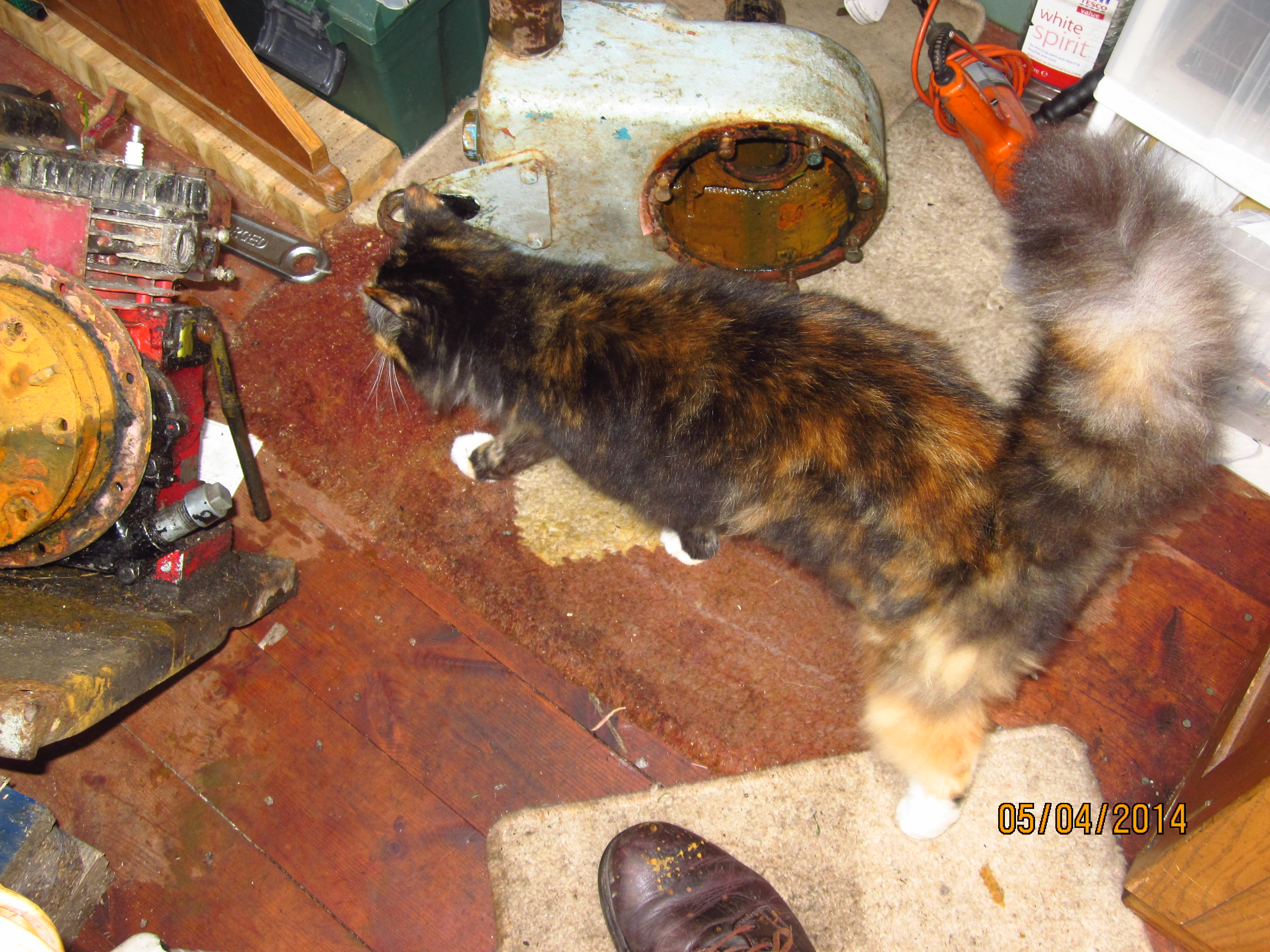
Started stripping the pump-set I bought recently. Removed the pump body from the engine but, the impeller is bolted securely to the crankshaft.
Any ideas on how to extract it. The securing nut appears to be 3/4BSW, is it LH thread ?
Logic would suggest so.
Any bright ideas on how to get it off ?Attachments:
April 5, 2014 at 7:18 pm #7129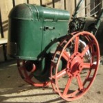 jtg1Participant
i’d warm it up with the blow torch and let it go cold. dont get it too hot though. do this half a dozen times plug the two holes up with a couple of wooden pegs, and fill the lot up with penetrating oil and leave for a while. make sure the socket you use is a very tight fit, preferably a hex one so you dont chew the corners off!
good luckApril 5, 2014 at 9:10 pm #7132 vhgmcbuddyMember
Is there a grease nipple in the the housing shaft on the opposite side to your photo ? if so fill a grease gun with diesel and squirt in as its cooling down from the applied heat. leave 2 or 3 days and give it a try. as jtg says block up the two holes first. good luck.
April 6, 2014 at 9:24 pm #7162sidevalve44ParticipantThanks for the info guys. Unfortunately can’t soak in diesel as the fluid would run out past the impeller vanes. Have sprayed liberally with GT85, and will use my garden flame thrower to try heating it up.
However, does anyone know if it is LH or RH thread ? Logic would suggest LH but, the Flywheel nut on the other side is LH thread, which is odd considering the crank rotation is clockwise.
Must find out somehow or other, before I end up mangling the threads by turning it the wrong way !!April 7, 2014 at 4:11 pm #7180vhgmcbuddyMemberSorry just been in for my second eye to be done and a replacement lens but by the look of the first picture I think you have to pull all that hair off it. Just be careful if you apply heat, don’t want the garage to catch fire.
Phil
April 7, 2014 at 5:45 pm #7194sidevalve44ParticipantHa ha ! She came in to see what I was doing. Couldn’t resist putting the photo on !
April 7, 2014 at 5:51 pm #7196 hillsiderParticipant
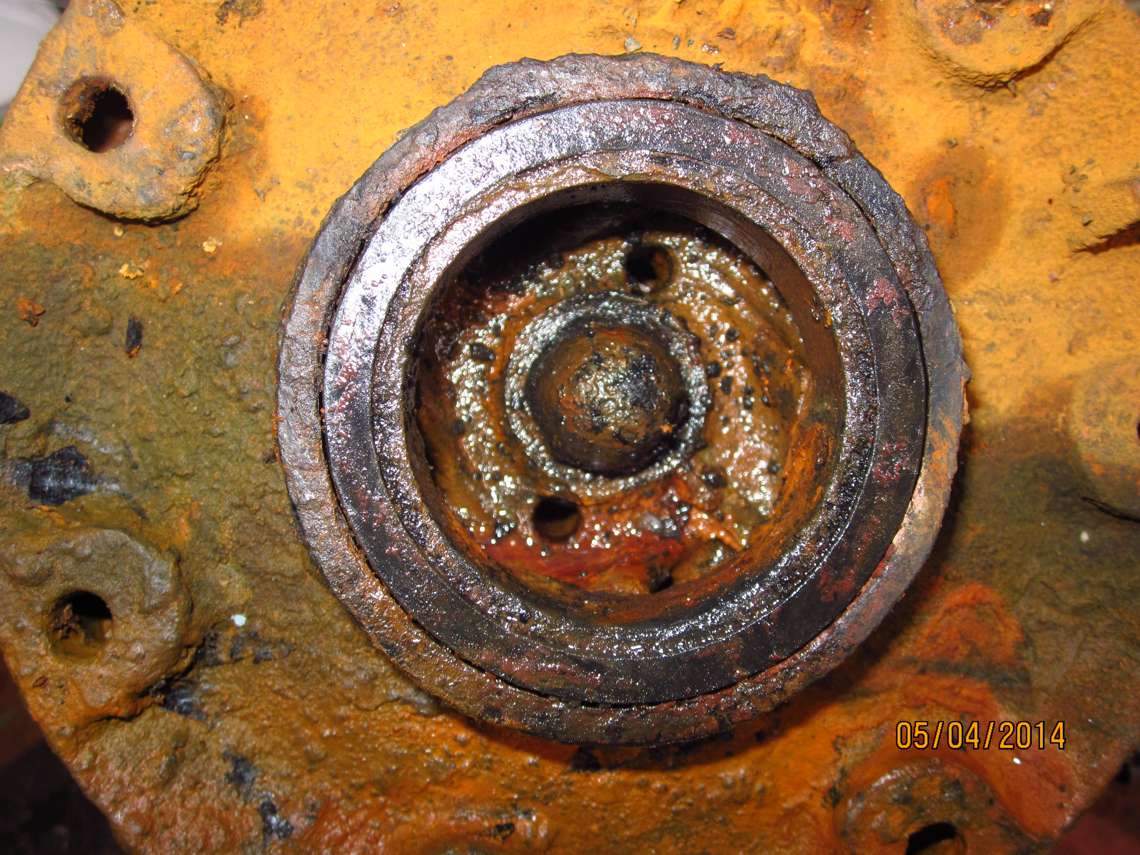
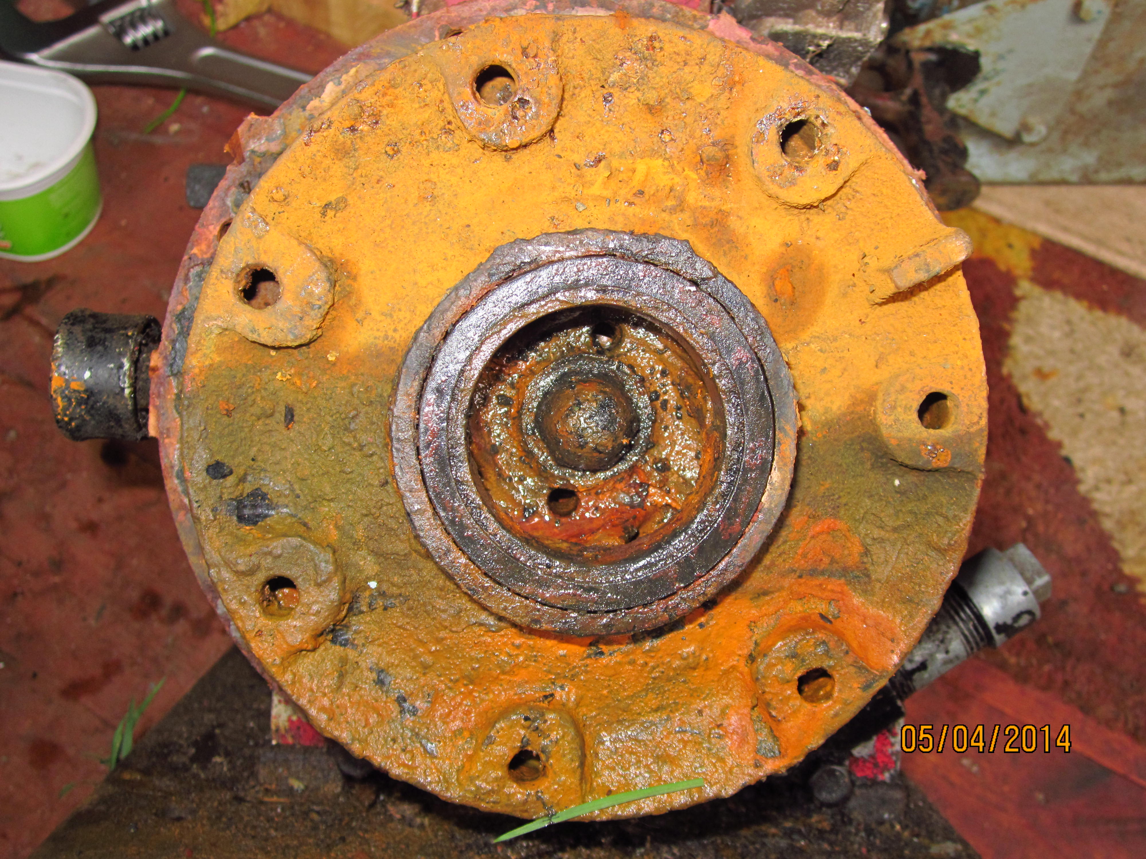
I have seen Pegson pumps as fitted to Blackstone marine diesel engines and just to be helpful they can be left or right handed dependent on the engine direction so tread care fully when you attack the impeller nut, I would suggest you lock the impeller (not the engine) and shock the spanner or socket with a hammer to release it. The two holes in the impeller are there to use as puller holes so that should help, also looks as though you still have the impeller shroud still in place on the centre boss of the impeller this may be why it was seized and could release with some heat.
Good luck Ray.April 7, 2014 at 6:06 pm #7201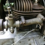 wristpinParticipant
If the engine rotation is counter clockwise when viewed from the impeller I would expect the nut to have a conventional right hand thread.
Ray’s suggestion that the two holes are for a puller (any sign of a thread in them?) would imply that it is either keyed to a parallel shaft or may be on a taper.
I suppose that in the absence of a parts list, there is the possibility that the “nut” could be part of the impeller and the whole lot screwed onto the shaft against a shoulder. Seem to recall an Alcon pump with that configuration .April 7, 2014 at 8:18 pm #7214hillsiderParticipantFrom memory the impeller will have a parallel shaft with a square section keyway and the nut is separate from the impeller and has a lock washer securing it.
I have just been having a rummage among some books that I have from my days working on such things and found a cross sectional parts diagram for the pumps that Lister Blackstone used and while it is similar in construction of the impeller arrangement the pump body and drive arrangement is completely different so probably not really much help to you.Just a thought but I seem to recall that the pump is fitted to a Briggs and Stratton engine, have you thought of looking up the engine using the Model, Type and Code numbers stamped on the flywheel housing from those numbers we may be able to find out what the drive end of the crankshaft is, this could help with the dismantling process.
April 8, 2014 at 9:06 am #7218 will-haggleParticipant
I’ve just searched on it and this firm may be able to help…
April 8, 2014 at 9:10 am #7220will-haggleParticipantThere is also a reference to it in the National Archives…
1/4/10-12 – 3″ Pegson-Marlow self-priming centrifugal pump/
Pegson Ltd., Coalville, Leicestershire. [4 photos, 3
views]
Here’s a link….https://www.nationalarchives.gov.uk/nra/onlinelists/GB%200069%20JAP.pdf
April 8, 2014 at 8:37 pm #7267sidevalve44ParticipantThanks. I now have some useful info to work on. Someone on another forum has stated that Pegson Pumps with JAP or Villiers engines have RH thread so, mine should be no different.
I have a copy of the B&S parts list and unfortunately, it is generic and doesn’t show the crank end.
Must admit I haven’t made a serious attempt to remove the impeller. Thought it best to pick a few brains first before I mangled it !
Yes, there is thread in the two little holes. Probably BSF. Will get my friendly engineer to knock me one up.
I think the shroud will come away once the impeller is freed off.
Will update once I have made further progress.
June 8, 2014 at 7:56 pm #8580sidevalve44ParticipantJust to follow up. The shaft is parallel and the impeller came off very easily using a 3 legged puller.
The actual impeller is inside a static housing which is part of the bearing housing attached to the engine’s crankcase.
I used the puller on this housing and it all came off together. -
AuthorPosts
- You must be logged in to reply to this topic.