Home › Forums › The Machinery Forums › Pedestrian operated machines › JP Super strip down and repair
- This topic has 5 replies, 1 voice, and was last updated 6 years, 3 months ago by
 charlie.
-
AuthorPosts
-
April 23, 2020 at 11:45 am #33962
 charlieKeymaster
When I was pushing this mower to the Land Rover to load up at GDSF last year it suddenly seized up and would not push forward or backward. A quick inspection did not reveal anything obvious, so it was loaded to be looked at another day.
The current lockdown has given me time to get the mower on the bench and investigate the problem further. A search of the internet for any advice about dismantling these mowers revealed nothing. Looking at the parts diagram it showed cotters that are used to hold the cross tubes in the frame. There are four of these; three on the underside and one on top.
After removing the chain and undoing the nut on end of the roller axle, I removed the cotter nuts and gave the cotters a gentle tap down into their holes, the holes are blind holes, so the cotters cannot be tapped right out, hoping this would release them from the cross tubes. No such luck. After a bit of thinking I decided to see if the cotter sleeves could be removed, after much gentle heating with the blow torch and plenty of penetrating fluid, not WD40, they did come out. Still no luck with getting side frame off though.
My next step was to carefully heat the frame around the area of each cross tube, care is needed not to use too much heat as the frame is aluminium. A combination of heat, penetrating fluid and careful use of the copper hammer, along with some ancient Anglo Saxon chants, and the frame was off. I have included photos of the cotters and how they sit in the frame to show how they grip the tubes when tightened.Attachments:
April 23, 2020 at 11:47 am #33968charlieKeymasterDetail of cotter in position.
Attachments:
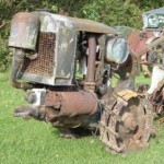
April 23, 2020 at 11:50 am #33970charlieKeymasterNow I could remove the rear roller, which revealed the first problem, one of the bearings had collapsed. The photo shows the state of the bearing and balls.
Attachments:
April 23, 2020 at 11:55 am #33972charlieKeymasterThe freewheel mechanism did not feel too smooth either so that was taken apart and revealed very badly pitted and worn balls.
Attachments:
April 23, 2020 at 12:04 pm #33976charlieKeymasterWhilst I had the rear roller out I decided to strip the centre section which contains gears to increase speed of the cutting cylinder. Removing the four machine screws that hold the two halves together showed the benefit of leaving penetrating fluid to soak in. With the tried and tested combination of heat, hammer and penetrating fluid I managed to get three of the four screws out. The fourth however was not having any of it, even using the SDS drill on hammer action would not persuade it to move. So I left it soak with penetrating fluid overnight, I use Plus Gas. Next day and the screw came undone without too much effort, the benefit of the overnight soak.
The photo shows the gears inside the centre section of the rear roller. I think it shows the high level of engineering used on these mowers.Attachments:
April 23, 2020 at 12:22 pm #33978charlieKeymasterThe only markings on the roller bearing that needed replacing were MRC 204S. After measuring the bearing and a search on the internet I found this was a metric sized bearing 6204. Measuring the balls from the freewheel showed them to be 3mm. Replacement bearings were ordered from Simply Bearings and arrived within a few days,very good service.
The new roller bearing was pressed onto the freewheel mechanism using a press. The old bearing had been removed using a split bearing removal tool, as it abuts the case of the freewheel.
Re-assembly of the freewheel was fun, a small amount of grease was used to hold the balls and spacers in place and a bit of wire was bent to shape and used to hold the pawls in place while the freewheel was assembled.
With the bearings replaced it was time to reassemble everything. One point to watch is the oil feed hole on the rear roller axle which must align with the hole in the frame where the filler tube screws in, see photo. The cotter bolts must be put in their respective holes before side frame can be fitted.
I found the easiest way to get the chain back on was to feed a length of thin wire in from the cutting cylinder sprocket to the rear roller then attach the chain to the wire and pull it into place. Then remove the wire and feed it in from the rear roller towards cutting cylinder and pull the chain through and join it up.
With everything bolted up one job to remember to do is fill the rear roller centre section with oil and you are ready to go.
I hope anyone needing to take a JP mower apart finds this article useful.Attachments:
-
AuthorPosts


- You must be logged in to reply to this topic.